Elenberg LVD-1902 User manual

Elenberg LVD-1902 SERVICE MANUAL
CONTENT
PART 1:Brief Introduction Of The LVD-1902
◆ Schematic Diagram
◆ Printed Circuit
PART 2: Exploded View
PART 3:Key Ics And Assemblies
PART 4: Detailed Circuit
◆ Main Board
◆ DVD Board
◆ HI-voltage Board
PART 5: Parts List
PART6: Debug Procedure

Part 1 Brief Introduction Of TheLVD-1902
Schematic Diagram
AMPLIFIER
AT49F040A
FLASH
CVBS
TPA3008
FLI8125
R G B
16V 5V
VHC4052
BH3547
LVDS
16V
BA5954
CVBS
MPS3415
74LVC125
DECODER
5V
DVD
L R
POWER SOURCE 100---240V AC 47HZ--63HZ 1.5A MAX
SIF
SWITCH
DIANYUAN
PANEL
16V
AV IN
Y C
FLASH
BACKLIGHT
MTK1389DE
TUNER
SVHS IN
YPBPR
L\R
IN
DECODER
AND
SCALER
3.3V
RGB/CVBS
INVERTER
YPBPR
K4S641632H
POWER
SUPPLY:16V
、
5V
、
3.3V
、
1.8V
L R
L R
SCART
AUDIO SWITCH
YPBPR
L R
RGB/YUV
L R
PC IN
LOADER
MOTOR DRIVER
FSAV330
MX29LV160
L R
VEDIO
HSI VSI
PHONE
SD-RAM
SPEAKER
AMPLIFIER
4 CCFL
IN
1.8V

Printed Circuit
1. Main board
A: TOP LAYER

B: BOTTOM LAYER

2. DVD board
A: TOP LAYER
B: BOTTOM LAYER

3. Power board
A: TOP LAYER
B: BOTTOM LAYER

4. Inverter board
A: TOP LAYER
B: BOTTOM LAYER

5. Remote Control Board
A: TOP LAYER
B: BOTTOM LAYER
6. Key board
A: TOP LAYER
B: BOTTOM LAYER

Part 2 Exploded view
Exploded view


Part 3 Key ICs And Assemblies
On Main Board On DVD board
Serial
No Position Type Serial
no Position Type
1 3U7 78L09 1 U2 BA033
2 4U5 LM1117MPX-3.3V 2 U3 AZ1117H-1.8V
3 2U3 4U6 FDS9435 3 U6 MT1389DE/E
4 4U2 AIC1084(3.3V) 4 U4 BA5954FP
5 4U1 TL494C 5 U5 BA6287
6 4U3 LM1117DTX-1.8V 6 U8 IS42S16400B-7T
7 3U4 CD4052 7 U9 MX29LV160BBTC-70
8 3U1 MSP3415G 8 U7 24C16
9 1U4 AT24C32AN 9 U11 NJM4558
10 1U1 FSAV330 10 U10 CS4344
11 2U1 AT49BV040B 11 U1 78L05
12 2U5 FLI8125-LF
13 3U6 TPA3008D2PHP
14 1U3 24C02
15 3U9 BH3547F
16 1U7 1U6 1U8 1U9 1U11 1U12 1U13
1U15 PESD5V0L5
On Power Board On Inverter Board
1 U5 FSCM0765RGWDTU 1 1C1 Bit3193
2 U2 PC817
3 U3 KA431AZ

ICS ON MAIN BOARD
1. FSAV330
Low On Resistance Quad SPDT Wide Bandwidth Video Switch

2. 74LVX125
Low Voltage Quad Buffer with 3-STATE Outputs.

3. AT49BVO40B


4. LM1117

5. FDS9435A
Single P-Channel Enhancement Mode Field Effect Transistor
SO-8 P-Channel enhancement mode power field effect transistors are produced using
Fairchild's proprietary, high cell density, DMOS technology. This very high density process is
especially tailored to minimize on-state resistance and provide superior switching
performance. These devices are particularly suited for low voltage applications such as
notebook computer power management and other battery powered circuits where fast
switching, low in-line power loss, and resistance to transients are needed.
·Features
-5.3 A, -30 V, RDS(ON) = 0.045 Ω@ VGS = -10 V,
RDS(ON) = 0.075 Ω@ VGS = - 4.5 V.
High density cell design for extremely low RDS(ON).
High power and current handling capability in a widely used surface mount package.

6.FLI8125
The FLI8125 is a cost-effective, highly-integrated, mixed signal solution for TV and Digital
Video applications. It incorporates a multi-standard video decoder, high-speed triple 8-bit
Analog-to-Digital Converter(ADC),and front end switching.An integrated VBI Slicer adds
Closed Captioning(CC) and Teletext service support, and the built-in microprocessor enables
full system control without external devices.
Features
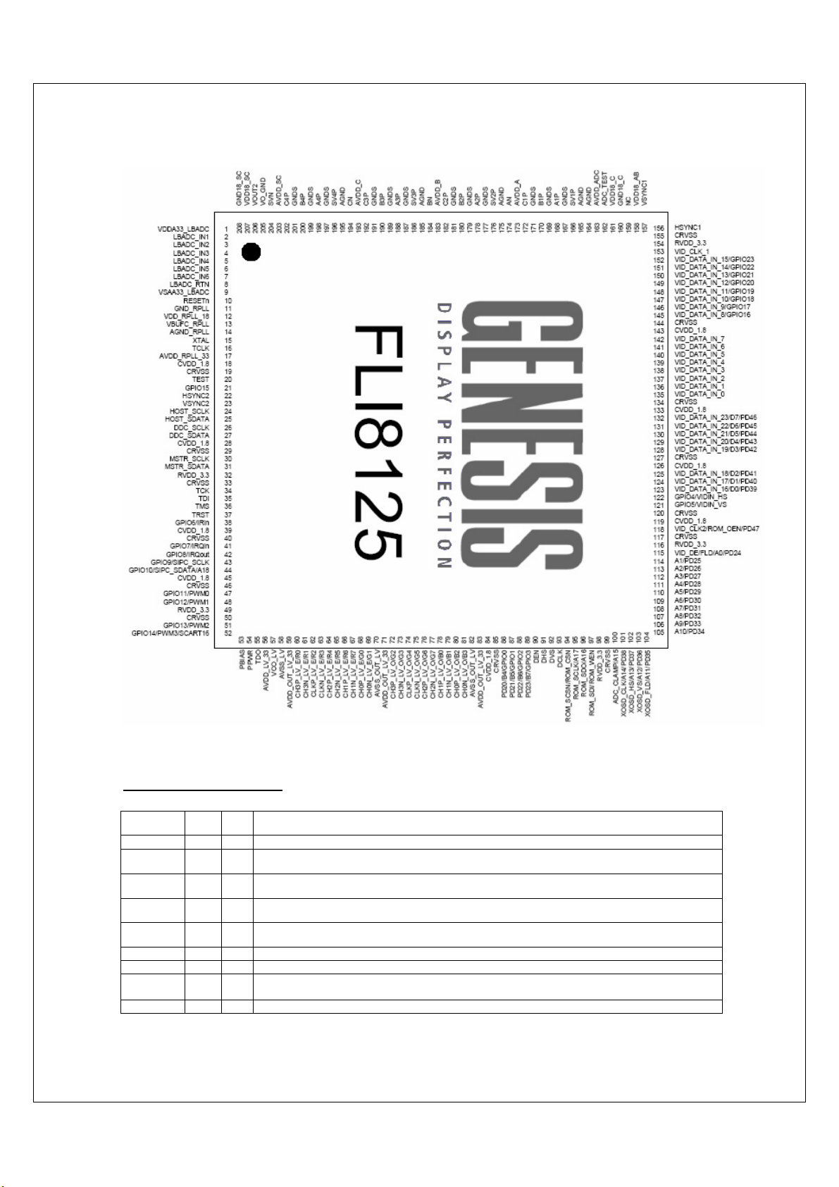
·PInput
·Pin List
I/O Legend: A = Analog, I = Input, O = Output, P = Power, G= Ground
Table 1: Analog Input Port
Pin Name No. I/O Description
VDD18_A
B 158 AP Analog Power (1.8V) for A & B Channels. Must be bypassed with 0.1uF capacitor to the analog system
ground plane.
NC 159 No Connection. Leave this pin open for normal operation.
GND18_C 160 AG Analog Ground (1.8V Return) for C channel. Must be directly connected to the analog system ground plane
on board.
VDD18_C 161 AP Analog Power (1.8V) for C Channel. Must be bypassed with 0.1uF capacitor to the analog system ground
plane.
ADC_TES
T 162 O Analog Front End Test O/P. Leave this Pin open. Used for factory testing purpose only.
AVDD_AD
C 163 AP Analog Power (3.3V) for ADC. Must be bypassed with 0.1uF capacitor to the analog system ground plane.
AGND 164 AG Analog Ground. Must be directly connected to the analog system ground plane on board.
AGND 165 AG Analog Ground. Must be directly connected to the analog system ground plane on board.
SV1P 166 AI Positive analog sync input for channel 1.
The input has to be AC coupled using a series 20 Ohm resistor and 0.1uF Capacitor network.
GNDS 167 AG Analog Ground. Must be directly connected to the analog system ground plane on board.
Other manuals for LVD-1902
1
Table of contents
Other Elenberg TV manuals


