V28CH1EUB
4
SAFETY PRECAUTIONS
1. The d esign of th is pr od uct con ta in s sp eci al har d wa re , ma ny
circuit s and components specially for safety purposes. For
con ti nu ed pr ot ection , n o chan g es sh ou ld b e ma de to the o rig inal
d esign un less a uth or ized in writin g by th e ma nu fact ur er.
Rep l acemen t p ar ts m ust b e id ent ic al to thos e u sed i n th e or igin al
circu it s. S er vice sho ul d b e p er for med by qu alif i ed p ers on nel
on ly.
2. Al te r ati on s of t he desig n or ci rcui tr y of t he pr od ucts sh ould not be
made. Any design alterations or additions will void the
m anu fact ur er 's w arr a nt y and w ill f ur th er r elieve t he ma nu factu rer
of r esp onsib ility for per so na l i njur y or p r op erty d am ag e r esul t in g
th er efr om .
3. M an y e lectri cal an d m ech ani ca l p ar ts i n th e pr od ucts ha ve
special safety-related characteristics. T hese characteristics are
oft en no t e viden t f r om vi sua l i nsp ection n or ca n t he pr o tect io n
aff or de d by th em nece ssar ily b e ob tain ed b y u sin g r ep lacem en t
com po ne nts ra ted f or hig he r vo ltag e, w att ag e, etc. Rep l acemen t
p arts wh ic h ha ve th ese sp ecial s afet y ch ar act er ist ics ar e
identified in the parts list of Servic e manual. El ec tric al
components having such features are identified by shading
on the sche matics and by (!
!!
!) on the parts list in Service
manual. The us e of a sub stitu te r ep la cemen t whi ch do es n ot
h ave th e sam e saf ety ch ar act er ist ics as t he r eco mmen de d
r eplac em ent par t sh own i n th e p ar ts l ist of S er vice m an ual m ay
cause shock, fire, or other hazards.
4. Do n't shor t between the LIVE side ground and ISOL ATED
(NEUTRAL) side ground or EARTH side ground when
repairing.
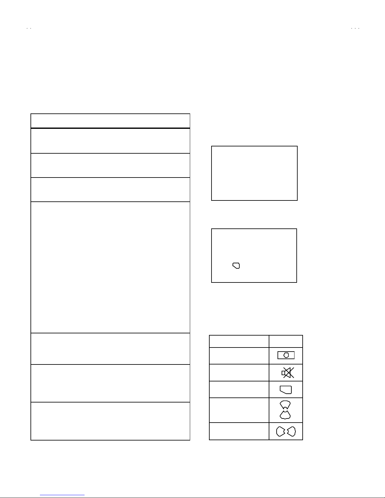
Some model's power circuit is partly different in the GND. The
diff er enc e of th e G ND i s sho wn b y th e LIV E : (") side GND, the
ISO LATE D(N EUTRAL) : ( #) side G ND and EARTH : ($) side
GN D. D o n't sh or t b et we en th e LIV E sid e GND an d
ISO LATE D(NEUTRAL) side GND or EARTH side GND and
n ever m ea sure w it h a m ea sur ing a ppa r atus ( oscillo scop e etc.)
th e LI VE sid e GND an d IS OLA TED (NE UTRAL ) sid e G ND or
EARTH side GND at th e s ame time.
If above note will not be kept, a fuse or any parts will be broken.
5. If any repair has been made to the chassis, it is recommended
th at t he B1 set ting shou ld b e ch ecke d or adj u ste d (Se e
ADJUSTMENT OF B 1 POW E R SU PPLY) .
6. The hi gh volta ge app lie d t o th e pi ctu r e tu be mu st con form w it h
th at sp ecified i n S er vice m an ual. E xcessive h i gh vo lt ag e ca n
cau se an incr e ase in X- Ray em ission , ar cing an d possib le
component damage, therefore operation under excessive high
voltage conditions should be kept to a minimum, or should be
preve nt ed. If s ever e arc in g occurs, r em ove t he AC power
imm ed iate l y an d de term ine th e ca use b y visua l i nsp ect io n
( in corr ect in stall at i on, cr acke d or m elte d hi gh vo lt age har n ess,
p oor so ld eri ng, et c.). To m aint ain the p r ope r min imu m l e vel of
sof t X- Ray em issi on, c omp on en ts i n th e high voltag e ci rcui tr y
incl ud ing t he pict ur e tu be must b e t he e xact r ep lacem e nts or
alte rn at ives ap pr ove d b y th e ma nuf act ur er of th e c om plet e
pr od uct.
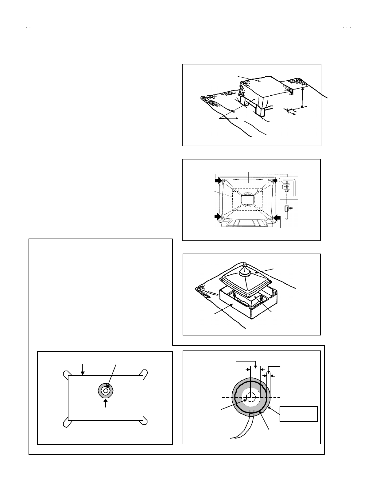
7. Do n ot c hec k high volt ag e b y drawing an ar c. Use a high volt ag e
m eter or a hi g h v ol tag e pr ob e wit h a V TVM . Di scha rg e th e
picture tube before attempting meter connection, by connecting
a cli p le ad to th e gr ou nd f ra me a nd c onn ectin g th e oth er end of
the lead through a 10k
Ω2W resisto r to the an od e b utt on .
8. W hen se r vi ce i s r equ ire d, ob ser ve th e or igina l l ea d dr ess. E xtra
pr ec aut i on sh ou ld b e g i ve n t o assur e cor rect lea d dr ess in th e
hig h vol tag e ci rcuit a r ea. W here a s hor t cir cuit h as occu rr e d,
th ose co mp on ent s tha t i ndica te evide nce of ove r hea ti ng sho ul d
b e r e place d. A l wa ys u se th e ma nuf act ur er's rep l acemen t
components.
9. Isolation Check
(Safety for Electrical Shock Hazard)
Af ter r e-ass emb lin g th e p r odu ct, al ways per f orm an i solat io n
ch eck on the expo sed me tal p arts of t he cabin et ( a nte nn a
ter m ina ls, vid eo /au di o i npu t and ou tpu t t er min als, C on tr ol kn obs,
m etal cabi n et, screw he ad s, ea r ph one j ack, con trol shaf ts, etc.)
to be su re th e p r odu ct i s s af e t o o pe r ate wi th ou t d an ger of
elect rical shoc k.
(1) Dielectric Strength Test
The i so l ati on be tween the A C pr ima ry circu it an d al l me tal p ar ts
exp ose d t o th e us er , p ar ti cular ly an y e xp os ed met al p art h avi ng a
r etu rn p ath to t he chass is sho ul d withs tan d a volt age of 3 000 V
AC (r.m.s.) for a period of one second.
( . . . . W it hstan d a vo lt ag e of 1 10 0V A C ( r.m. s.) t o an ap pli anc e
r ate d up to 12 0V , an d 3 00 0V AC ( r .m. s.) to an ap pl ian ce r at ed
200V or more, for a periodof one second.)
This method of test requires a t est equipment not g enerally found
in t he servic e trad e.
(2) Leakage Current Check
Pl ug th e A C l in e c ord d ir ect l y in to th e A C ou tlet ( d o n ot use a lin e
isol atio n transf or mer du rin g this ch eck.) . U sin g a " Lea kag e
Cur r ent Teste r", me asur e th e l ea kag e cu rre nt f rom each exp osed
m etal p art of the ca bine t, p art icu lar ly any e xpos ed me tal p art
h aving a re turn pa th to t he ch assis , t o a kn own go od ea rt h
gr ou nd (wa ter pip e, e tc.). An y leaka ge cur r en t m ust n ot e xceed
0.5mA AC (r.m.s.).
How eve r, i n tr op ic al ar ea , th is mu st no t exce ed 0.2 mA AC
(r.m.s.).
"
""
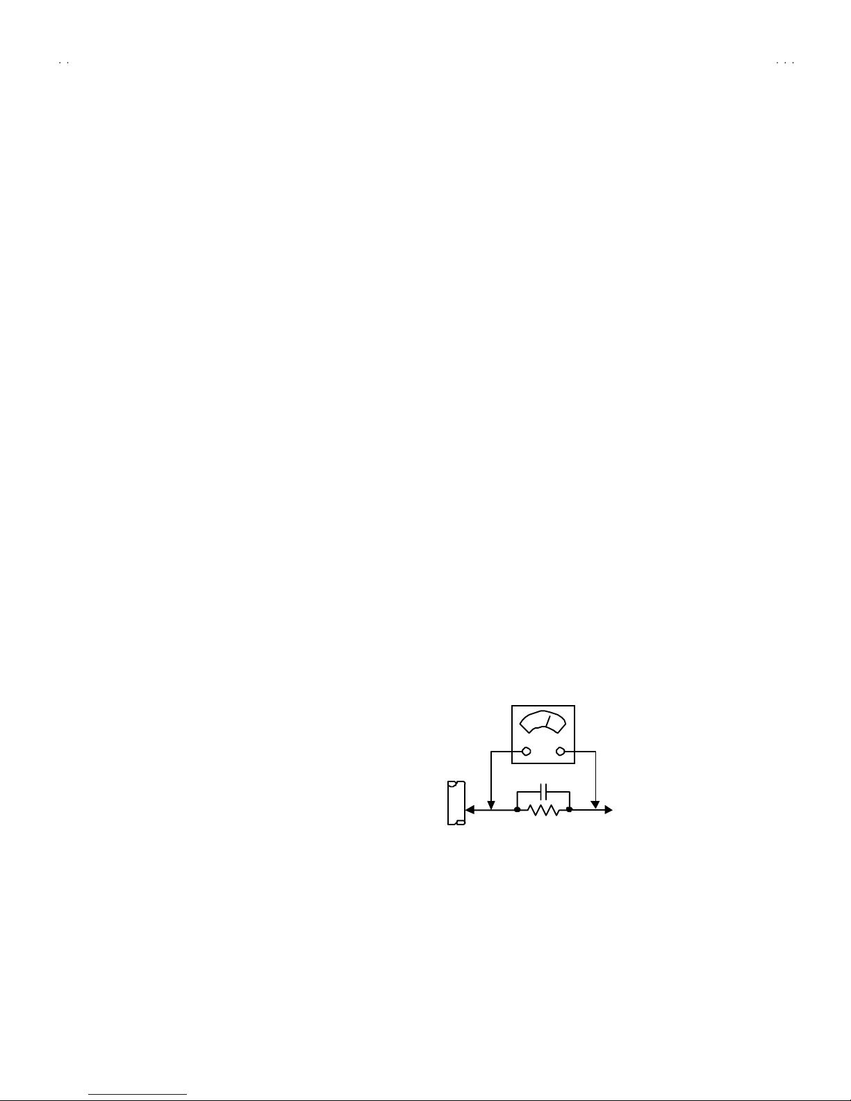
"Alte rnat e Che ck M et ho d
Pl ug th e A C l in e c ord d ir ect l y in to th e A C ou tlet ( d o n ot use a lin e
isol atio n tr an sfor mer duri ng t hi s che ck.). Use an AC vo lt me ter
h aving 1 00 0 oh ms pe r volt or mor e sens it i vity in th e fo ll owing
m ann er. Con nec t a 1 50 0Ω10W res ist or par a ll e le d b y a 0 .1 5µF
AC -type c apa cit or bet we en an expo sed met al pa rt a nd a kno wn
g ood e ar th gr o un d ( wa ter pipe , etc.). M eas ur e th e A C vo lt ag e
acr oss th e r es ist or w ith th e AC vo ltm eter . M ove th e r esistor
con nec ti on to e ach exp ose d me tal par t, p art i cul arl y a ny exp osed
m etal p ar t havin g a r etu rn pat h to t he ch assis, an d m easu r e th e
AC vol tag e ac ro ss the r es ist or . No w , re verse th e pl u g i n th e AC
ou tl et and r e pe at eac h m ea sur emen t. An y vol t ag e me asu re d
must not exc eed 0 .7 5V AC (r.m.s.). This c orresponds to 0.5mA
AC (r.m.s.).
However, in tropical area, this must not exceed 0 .3V AC ( r.m. s.).
This corresponds to 0.2mA AC (r.m.s.).
0.15μF AC-T YPE
1500 Ω10W
GOODEARTH GROUND
PLACE THIS PROBE
ON E A C H EX PO SE D
ME T AL PA R T
ACVOLTMETER
(HAVING 1000 Ω/V,
OR MOR E SENSIT IVITY)