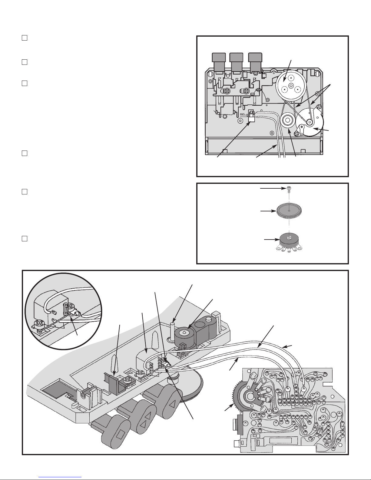
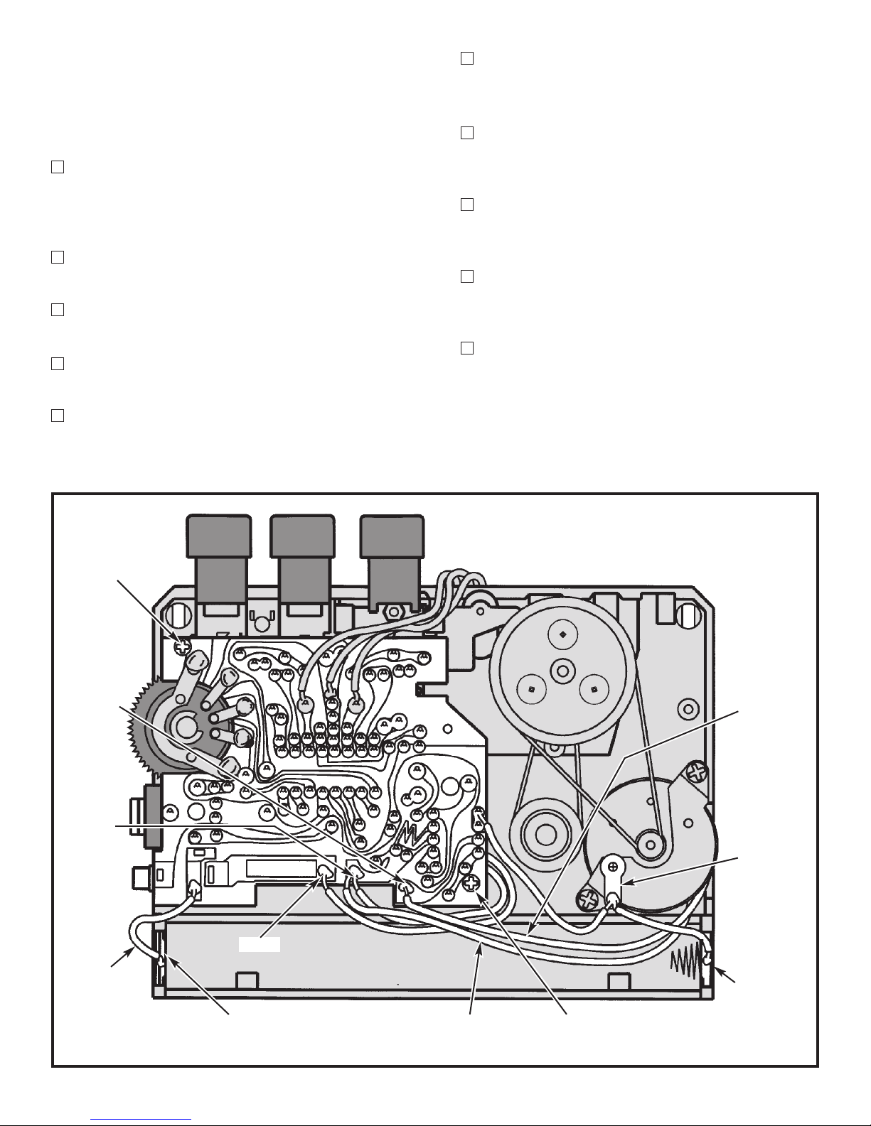
Elenco Electronics AK-200 User guide

CASSETTE PLAYER KIT
MODEL AK-200
Assembly and Instruction Manual
ElencoTM Electronics, Inc.
Copyright © 1994 ElencoTM Electronics, Inc. Revised 2003 REV-L 753260

Qty. Description Part #
1 PC Board 517020
1 Battery Contact + 610815
1 Battery Contact – 610816
1 DC Jack 2.5mm 621013
1 Phone Jack 3.5mm 621015
1 Top Plate 623106
1 Bottom Plate 623204
1 Thumb Wheel 626006
1 Tape Deck 626007
1 Lid 626008
1 Clip 626009
Qty. Description Part #
1 Battery Cover 626011
1 Stereo Headset 629202
2 Screw 7/32” 643150
1 Screw 3/32” 643155
2 Screw 1” Black 643196
1 Socket IC 8-pin 664008
1 Wire 1.6” Red 825320
2 Wire 2.8” Black 834510
4 Wire 2.8” Red 834522
1 Wire 1.2” Bare 845400
1 Solder 9ST4
SECTION 1 - PARTS LIST
If any parts are missing or damaged, see instructor or bookstore. DO NOT contact your place of purchase as
they will not be able to help you. Contact ElencoTM Electronics (address/phone/e-mail is at the back of this
manual) for additional assistance, if needed. RESISTORS
Qty. Symbol Value Color Code Part #
2 R1, R2 390W5% 1/4W orange-white-brown-gold 133900
1 R7 1kW5% 1/4W brown-black-red-gold 141000
1 R8 8.2kW5% 1/4W gray-red-red-gold 148200
2 R3, R6 12kW5% 1/4W brown-red-orange-gold 151200
2 R4, R5 180kW5% 1/4W brown-gray-yellow-gold 161800
1 VR2 1kWPotentiometer 191411
1 VR1 50kWPotentiometer 191533
CAPACITORS
Qty. Symbol Value Description Part #
3 C5, C6, C16 0.001mF (102) Discap 231035
2 C20, C21 0.005mF (502) Discap 235016
4 C1, C2, C18, C19 0.02mF (203) Discap 242010
1 C17 0.1mF (104) Discap 251010
4 C3, C4, C10, C13 10mF Electrolytic (Lytic) 271045
4 C9, C12, C14, C15 100mF Electrolytic (Lytic) 281024
1 C11 220mF Electrolytic (Lytic) 282223
SEMICONDUCTORS
Qty. Symbol Value Description Part #
1 IC2 AN6650 Integrated Circuit 336650
1 IC1 AN7108 Integrated Circuit 337108
MISCELLANEOUS
-1-
Resistor Capacitors
Phone Jack
PARTS IDENTIFICATION
Electrolytic Discap
Semiconductors
Integrated Circuits
16-Pin
8-Pin
DC Jack
Positive
(+)
1kW
WPot
50kW
WPotentiometer
Battery Contacts
Negative
(–)
Thumb Wheel

-2-
IDENTIFYING RESISTOR VALUES
Use the following information as a guide in properly identifying the value of resistors.
BAND 1
1st Digit
Color Digit
Black 0
Brown 1
Red 2
Orange 3
Yellow 4
Green 5
Blue 6
Violet 7
Gray 8
White 9
BAND 2
2nd Digit
Color Digit
Black 0
Brown 1
Red 2
Orange 3
Yellow 4
Green 5
Blue 6
Violet 7
Gray 8
White 9
Multiplier
Color Multiplier
Black 1
Brown 10
Red 100
Orange 1,000
Yellow 10,000
Green 100,000
Blue 1,000,000
Silver 0.01
Gold 0.1
Resistance
Tolerance
Color Tolerance
Silver +10%
Gold +5%
Brown +1%
Red +2%
Orange +3%
Green +.5%
Blue +.25%
Violet +.1%
BANDS
12 Multiplier Tolerance
IDENTIFYING CAPACITOR VALUES
Capacitors will be identified by their capacitance value in pF (picofarads), nF (nanofarads), or mF (microfarads). Most
capacitors will have their actual value printed on them. Some capacitors may have their value printed in the following
manner. The maximum operating voltage may also be printed on the capacitor.
Second Digit
First Digit
Multiplier
Tolerance The letter M indicates a tolerance of +20%
The letter K indicates a tolerance of +10%
The letter J indicates a tolerance of +5%
FortheNo.01234589
Multiply By 1 10 100 1k 10k 100k .01 0.1
Multiplier
Note: The letter “R” may be used at times
to signify a decimal point; as in 3R3 = 3.3
103K
100V
Maximum Working Voltage
The value is 10 x 1,000 = 10,000pF or .01mF 100V
10mF 16V
METRIC UNITS AND CONVERSIONS
Abbreviation Means Multiply Unit By Or
p Pico .000000000001 10-12
n nano .000000001 10-9
mmicro .000001 10-6
m milli .001 10-3
– unit 1 100
k kilo 1,000 103
M mega 1,000,000 106
1. 1,000 pico units = 1 nano unit
2. 1,000 nano units = 1 micro unit
3. 1,000 micro units= 1 milli unit
4. 1,000 milli units = 1 unit
5. 1,000 units = 1 kilo unit
6. 1,000 kilo units = 1 mega unit

-3-
SECTION 2 - INTRODUCTION
It is the goal of this project to educate the builder in
the principles of magnetic tape recording and to teach
the skills necessary to build this kit. The AK-200
Stereo Cassette Player is divided into two parts -
Motion Control and Audio. This manual contains:
1) Detailed assembly instructions for each part. For
ease of assembly, both parts are built at the
same time.
2)
Specifications and a test procedure for each part
coupled with a troubleshooting guide for each test.
3) An explanation for each part (Theory of
Operation).
In addition, specifications and a schematic diagram
are given. A Quiz (with answers) is included to
demonstrate the overall knowledge gained by
building this kit.
SECTION 3 - GENERAL OVERVIEW
The main features of the Model AK-200 Stereo
Cassette Player are:
a) Plays 4 track 0.15” tape cassettes. Two tracks are
played at the same time. When the cassette
reaches the end of the tape, it can be turned over
and reinserted to play the remaining two tracks.
b) Drives stereo headphones.
c) Runs on two “AA” size batteries or an external 3
volt power supply via an AC adapter (not
included).
Figure 3-1 shows a block diagram of the cassette
player. No mechanical assembly is required on the
tape deck. It comes completely pre-assembled and
pre-aligned. You need only to build the PC board,
wire it to the tape deck, insert the batteries and the
tape cassette and you are ready for your favorite
kind of music.
Figure 3-1
Tape Drive
(Motor, Pulleys)
Pushbutton
Controls Heads
Motion
Control Audio Earphones
Tape Deck
Assembly

-4-
TAPE DECK ASSEMBLY
See Figures 5-3 and 5-5.
Tape Deck Assembly consists of three main parts:
1)
Tape Drive Train - The Tape Drive Train contains
a motor which turns at a constant speed. The
motor is connected by a drive belt to a large
pulley which turns the capstan. When the AK-200
is in Play Mode, that is, with the Play button
pushed, the pinch roller clamps the tape against
the capstan. This causes the tape to be pulled
across the head at a constant speed.
At the start of tape play, the tape is winding onto
an empty take-up reel. As the tape builds up on
the take-up reel, it takes more tape to go once
around the reel. Since the tape is moving at a
constant speed, the take-up reel must turn faster
at the start of tape play than at the end. A belt
from the capstan drives a small pulley to turn the
take-up reel. This pulley, if it were rigidly
connected to the take-up reel, would drive the
reel much faster than required even at the start of
tape play. A slip clutch is therefore inserted
between the small pulley and the take-up reel to
allow the reel to turn at the different speeds
required to wind up the tape.
2) Push-button Controls - Three push-buttons
control tape play. Pushing any button places the
AK-200 in that mode until another button is
pushed.
Play - Pushing the PLAY button closes the ON
switch which supplies power to the motor, motion
control and audio amplifier electronics. In
addition, the head and tape guide are moved into
contact with the tape and the pinch roller clamps
the tape against the capstan. You may then listen
to the tape through the stereo headphones.
Fast Forward - Pushing FAST FORWARD closes
the ON switch which, as in PLAY mode, supplies
power to the motor, motion control and audio
amplifier electronics. The head, tape guide and
pinch roller are not moved into contact with the
tape. The tape is therefore driven solely by the
take-up reel. Since there is little drag, there is
little or no slippage in the slip clutch and the tape
moves forward at high speed. FAST FORWARD
is used to space forward to a particular section of
tape or, after using the tape over, for rewinding.
Stop - Pushing STOP takes the AK-200 out of PLAY
or FAST FORWARD mode and stops the tape. After
opening the lid, STOP may be used again to pop up
the tape cassette for easy removal.
3) Heads - The purpose of the heads is to convert
the magnetization on the tape into an electrical
signal. The AK-200 has two playback heads.
Each head plays one of the four tape tracks when
the cassette is inserted one way and another
track when the tape is turned over.
MOTION CONTROL
When the two 1.5V batteries are new, they put out
their full 3V rated voltage. In time, as the batteries
are used, this voltage drops. If the battery voltage
was applied directly to the motor, the motor would
slow down as the battery voltage dropped. Tape
speed would then decrease, causing music to be off
key and voices to sound too low. The Motion
Control Section is therefore used to keep a constant
voltage on the motor and insure uniform tape speed.
AUDIO AMPLIFIERS
The audio amplifier section consists of two separate
amplifiers, one for each head, each amplifier driving
one of the stereo headphone speakers. The gain of
both amplifiers is set by the thumb wheel on the side
of the tape player. The amplitude on the low
frequencies from the head is lower than that of the
high frequencies. The frequency response of the
amplifiers is therefore set to emphasize the lows
and thus equalize the overall response.

-5-
Introduction
The most important factor in assembling your AK-200 Stereo Cassette Player Kit is good soldering techniques.
Using the proper soldering iron is of prime importance. A small pencil type soldering iron of 25 - 40 watts is
recommended. The tip of the iron must be kept clean at all times and well tinned.
Safety Procedures
• Wear eye protection when soldering.
•
Locate soldering iron in an area where you do not have to go around it or reach over it.
•Do not hold solder in your mouth. Solder contains lead and is a toxic substance. Wash your hands
thoroughly after handling solder.
• Be sure that there is adequate ventilation present.
Assemble Components
In all of the following assembly steps, the components must be installed on the top side of the PC board unless
otherwise indicated. The top legend shows where each component goes. The leads pass through the
corresponding holes in the board and are soldered on the foil side.
Use only rosin core solder of 63/37 alloy.
DO NOT USE ACID CORE SOLDER!
CONSTRUCTION
Solder Soldering Iron
Foil
Solder
Soldering Iron
Foil
Component Lead
Soldering Iron
Circuit Board
Foil
Rosin
Soldering iron positioned
incorrectly.
Solder
Gap
Component Lead
Solder
Soldering Iron
Drag
Foil
1. Solder all components from
the copper foil side only.
Push the soldering iron tip
against both the lead and
the circuit board foil.
2. Apply a small amount of
solder to the iron tip. This
allows the heat to leave the
iron and onto the foil.
Immediately apply solder to
the opposite side of the
connection, away from the
iron. Allow the heated
component and the circuit
foil to melt the solder.
1. Insufficient heat - the
solder will not flow onto the
lead as shown.
3. Allow the solder to flow
around the connection.
Then, remove the solder
and the iron and let the
connection cool. The
solder should have flowed
smoothly and not lump
around the wire lead.
4.
Here is what a good solder
connection looks like.
2. Insufficient solder - let the
solder flow over the
connection until it is
covered. Use just enough
solder to cover the
connection.
3. Excessive solder - could
make connections that you
did not intend to between
adjacent foil areas or
terminals.
4. Solder bridges - occur
when solder runs between
circuit paths and creates a
short circuit. This is usually
caused by using too much
solder. To correct this,
simply drag your soldering
iron across the solder
bridge as shown.
What Good Soldering Looks Like
A good solder connection should be bright, shiny,
smooth, and uniformly flowed over all surfaces.
Types of Poor Soldering Connections

-6-
SECTION 5 - ASSEMBLY INSTRUCTIONS
TOOLS NEEDED: Small Blade Screwdriver, Phillips Screwdriver (small point size), Diagonal Cutters, Long
Nose Pliers and a Soldering Iron (25 - 40 watts).
PC BOARD ASSEMBLY - Your kit may contain several extra capacitors and wires. Please disregard these parts.
Identify and install the following parts as shown in Figure 5-1. After soldering each part, place a check in the
box provided.
C6 - .001mF (102) Capacitor
(Lay flat on board)
C5 - .001mF (102) Capacitor
(Lay flat on board)
C3 - 10mF Lytic Capacitor
(see Figure C)
R1 - 390W5% 1/4W Resistor
(orange-white-brown-gold)
C1 - .02mF (203) Capacitor
R3 - 12kW5% 1/4W Resistor
(brown-red-orange-gold)
R4 - 180kW5% 1/4W Resistor
(brown-gray-yellow-gold)
C7 - Jumper Wire
(see Figure A)
C20 - .005mF (502) Capacitor
(This location may not be marked
on the PC board. Use the picture.)
C8 - This is not used.
VR2 - 1kWPotentiometer
(see Figure B)
R7 - 1kW5% 1/4W Resistor
(brown-black-red-gold)
8-pin IC Socket
IC2 - AN6650 Integrated Circuit
(see Figure D)
C16 - .001mF (102) Capacitor
C17 - .1mF (104) Capacitor
R8 - 8.2kW5% 1/4W Resistor
(gray-red-red-gold)
C11 - 220mF Lytic Capacitor
(see Figure C)
Jumper Wire (see Figure A)
C12 - 100mF Lytic Capacitor
(see Figure C)
Figure A
Use a discarded resistor lead
for a jumper wire.
Figure B
Figure C
These capacitors are polarized.
Be sure to mount them with the
“+” lead in the correct hole as
marked on the PC board. Mount
the capacitor lying flat on the PC
board as shown below.
(–) (+)
Figure 5-1

Figure Da
Insert the IC into the PC board with
the notch in the same direction as
the marking on the PC board.
Figure D
Insert the IC socket into the PC
board with the notch in the
direction as the marking on the PC
board. Solder the IC socket into
place. Insert the IC into the socket
with the notch in the same direction
as the notch on the socket.
-7-
ASSEMBLY CONTINUED
Identify and install the following parts as shown in Figure 5-2. After soldering each part, place a check in the
box provided.
PC Board
R2 - 390W5% 1/4W Resistor
(orange-white-brown-gold)
C4 - 10mF Lytic Capacitor
(see Figure C)
C2 - .02mF (203) Capacitor
R6 - 12kW5% 1/4W Resistor
(brown-red-orange-gold)
R5 - 180kW5% 1/4W Resistor
(brown-gray-yellow-gold)
C21 - .005mF (502) Capacitor
C9 - 100mF Lytic Capacitor
(see Figure C)
C18 - .02mF Capacitor
(This location may not be marked
on the PC board. Use the picture.)
Phone Jack (see Figure E)
C19 - .02mF Capacitor
(This location may not be marked
on the PC board. Use the picture.)
DC Jack (see Figure F)
C15 - 100mF Lytic Capacitor
(see Figure C)
IC1 - AN7108 Integrated Circuit
(see Figure Da)
C14 - 100mF Lytic Capacitor
(see Figure C)
C13 - 10mF Lytic Capacitor
(see Figure C)
C10 - 10mF Lytic Capacitor
(see Figure C)
Figure E
Phone Jack
Figure F
DC Jack
Notch
AN7108 IC
Figure 5-2
Notch
Socket
PC Board
AN6650 IC

TAPE DECK ASSEMBLY
Solder two red 2.8” wires to the ON switch as
shown in Figure 5-3.
Mount the thumb wheel to pot VR1 as shown in
Figure 5-4.
See Figure 5-5. PUSH THE POTTO THE RIGHT
AGAINST THE PC BOARD so that the thumb
wheel will not hit the top or bottom plate when
the unit is completely assembled. Then solder
the pot in place as shown in Figure 5-5. It is
helpful to Scotch®Tape VR1 in position leaving
one or two terminals open to solder the
remaining terminals.
Solder two red 2.8” wires to the two head terminals
and the PC board as shown in Figure 5-5.
NOTE: The head may have only two terminals.
If so, solder to those terminals.
Connect a 1.2” piece of bare wire to the two/four
head terminals and the head common terminal
as shown in Figure 5-5. Solder the wire to the
two/four head terminals but not to the head
common terminal.
Solder one end of a 2.8” black wire, and the bare
wire from the head, to the head common
terminal. Solder the other end of the black wire
to the PC board as shown in Figure 5-5.
-8-
Figure 5-4
Thumb
Wheel
3/32”
Screw
50kWPot
(VR1)
Figure 5-3
Stop
Fast
Forward Play
Large Pulley
Drive
Belts
Motor
Small PulleyRed WiresON Switch
2 Head
Bare Wire
Figure 5-5
Head Common
Terminal
Capstan
Pinch Roller
Bare Wire
Black Wire
Red Wire
Red Wire
Tape Guide
4 Head
VR1

-9-
CONNECTING THE PC BOARD - See Figure 5-6.
The wires connected to the PC board should be
positioned so that they do not touch the pulleys or
drive belts and do not interfere with the placement
of the batteries.
Fasten the PC board to the tape deck using two
7/32” screws as shown in Figure 5-6. Be sure the
two wires from the ON switch are accessible at
the right of the PC board.
Insert the (+) and (–) battery terminals into their
slots as shown in Figure 5-6.
Solder the 1.6” red wire to the (+) battery terminal
and the PC board as shown in Figure 5-6.
If there are any wires already attached to the
motor case terminal, remove them.
Cut a black 2.8” piece of wire into two 1.4”
pieces. Strip 1/8” of insulation off the new end of
both wires. Solder one end of both 1.4” wires to
the motor case terminal as shown in Figure 5-6.
Solder the other end of one of the wires on the
motor case terminal to the PC board as shown in
Figure 5-6.
Solder the other end of the remaining 1.4” wire
on the motor case terminal to the (–) battery
terminal as shown in Figure 5-6.
Solder one end of the red 2.8” wires from the ON
switch to point A on the PC board as shown in
Figure 5-6.
Solder the other red 2.8” wire from the ON switch
and the red wire from the motor to point B on the
PC board as shown in Figure 5-6.
Solder the black wire from the motor to point C
on the PC board as shown in Figure 5-6.
Point A
Figure 5-6
Point B
7/32” Screw
Black
Motor Case
Terminal
(–) Battery
Terminal
7/32” ScrewRed(+) Battery Terminal
Red
Wire
Point C

-10-
SECTION 6 - TEST PROCEDURE - MOTION CONTROL
MOTOR SPEED TEST
1. Insert two “AA” size batteries into the battery
compartment. See Figure 5-6 for polarity.
2. Set VR2 to midway between its two extremes.
3. Insert a tape cassette and push the PLAY button.
If the tape runs out during testing, turn it over and
play the other side. Do not perform the tests with
the tape reels not moving.
4. Observe that the motor turns and that the tape
moves across the head. If it does not:
a) Check that the batteries are good.
b) Check that both drive belts are seated
correctly on their pulleys.
c) Check that the wires to the PC board are
wired as shown in Figures 5-3 and 5-6.
d) Check that the ON switch closes when the
PLAY button is pushed. See Figure 5-3.
e) Check that IC2 is mounted with the notch as
shown in Figure 5-1.
f) Check the soldering at IC2. Be sure that
there are no solder shorts between the pins.
g) Check for a gap between the pulley and
motor. If there is no gap, then loosen the
screws mounting the motor and move it to
the right (see Figure 6-1).
5. Turn VR2 fully counter-clockwise. Observe that
the motor turns faster. Turn VR2 fully clockwise.
Observe that the motor turns slower. If either of
these tests fail:
a) Check the value of R7 and R8 as shown in
Figure 5-1.
b) Check the soldering around R7, R8, VR2
and IC2.
6. Reset VR2 to midway between its two extremes.
7.
Tests 7 and 8 require a voltmeter. If you do not
have a voltmeter, go on to test 9. Connect the
voltmeter between point A (+ lead) and C (– lead)
to measure the reference voltage (see Figure 6-2).
It should be close to 1.3V. If it is not 1.3 +0.05V:
a) Check the values of R7 and R8.
b) Check the soldering around R7, R8, VR2
and IC2.
8. Connect the voltmeter between points A (+ lead)
and B (– lead) to measure the motor voltage (see
Figure 6-2). It should be approximately 1.8V. If
it is not:
a) Check the values of R7 and R8.
b) Check the soldering around R7, R8, VR2 and
IC2.
c) Check that the motor is wired to the PC
board as shown in Figure 5-6.
9. Push the FAST FORWARD button. Observe that
the tape moves forward faster than when in
PLAY mode. If it does not:
a) Check the wiring to the ON switch.
b) Check that the PC board does not interfere
with the STOP button.
IMPORTANT: When using the PLAY, F.FWD, and
STOP controls, be sure to push the button straight
down. Pushing the button sideways can cause it to
jam.
To repair a loose button on the cassette player,
apply some glue on the sides of the button and slide
it back over the control arm.
Figure 6-2
A B C
VR2
ADJUST
Figure 6-1
Gap

-11-
SECTION 7 - TEST PROCEDURE - AUDIO
Tests 3 through 7 require a voltmeter. If you do not
have a voltmeter, skip these tests to go on to test 8.
AUDIO TESTS
See Figure 7-1 for test point connections.
1. Insert two “AA” size batteries into the battery
compartment. See Figure 5-6 for polarity.
2. Insert a tape cassette and push the PLAY button.
If the tape runs out during testing, turn it over and
play the other side. Do not perform the tests with
the tape reels not moving.
3. Connect a voltmeter between point A (+ lead)
and point G (– lead) to measure the input
voltage. It should be around 3 volts. Record the
input voltage: ________V.
4. Connect the voltmeter between point B (+ lead)
and point G (– lead) to measure the reference
voltage. It should be 1/2 of the input voltage
+0.2V. If it is not:
a) Check the wiring between the ON switch and
the PC board.
b) Check that IC1 is mounted with the notch as
shown in Figure 5-1.
c)
Check the soldering around IC1, R2, R3, VR1
& C9.
5. Connect the voltmeter between point C (+ lead)
and point G (– lead) to measure the driver DC
output voltage (amplifier A, pin 14). It should be
1/2 the input voltage +0.3V. If it is not:
a) Check the soldering around IC1 and C15.
6. Connect the voltmeter between point D (+ lead)
and point G (– lead) to measure the driver DC
output voltage (amplifier A, pin 14). It should be
1/2 the input voltage +0.3V. If it is not:
a) Check the soldering around IC1 and IC2.
7. Connect the voltmeter between point E (+ lead)
and point G (– lead) to measure to volume
control voltage to pin 9. Rotate the thumb wheel
fully clockwise. The volume control voltage
should be within 0.1V of the reference voltage
measured in Step 4 on the previous page.
Rotate the thumb wheel fully counter-clockwise.
The volume control voltage should be less than
0.1V. If either of these tests fail:
a) Check that the thumb wheel will turn about
240 degrees.
b) Check the soldering around IC1, VR1, and
C9.
c) Check the value and soldering of R1 and R2.
8. Plug the stereo headset into the phone jack and
listen to your tape. Check that the thumb wheel
adjusts the playback volume. If it does not:
a) Check that the head is wired to the PC board
as shown in Figure 5-5.
b) Check that all other wires are wired to the PC
board as shown in Figure 5-6.
c) Check that both drive belts are seated
correctly on their pulleys.
d) Check that the thumb wheel will turn about
240 degrees.
e) Check the soldering around IC1, VR1 and
C9.
f) Check the value and soldering of R1 and R2.
9. Adjust VR2 so that the pitch and tempo of the
music sound right. If it cannot be adjusted
properly:
a) Check that both drive belts are seated
correctly on their pulleys.
b) Check the soldering around IC2 and VR2.
c) Check the value and soldering around R7
and R8.
Figure 7-1
B
E
C
G
D A
16
1
9
8
45
18

-12-
SECTION 8 - FINAL ASSEMBLY
Place the tape deck on the bottom plate. Be sure
that the wires to the PC board do not touch the
pulleys or drive belts and will not interfere with
the batteries. Snap on the top plate and fasten
with two 1” screws as shown in Figure 8-1.
If not already in place, snap the lid onto the
bottom plate as shown in Figure 8-1.
Place the clip over the three mounting holes in
the top plate as shown in Figure 8-2. Press down
to snap the clip onto the top plate.
Put two “AA” size batteries (alkaline works best)
into the AK-200. The polarity is shown on the
case. Then, slide the battery cover in place as
shown in Figure 8-2.
Figure 8-1
Figure 8-2
Top Plate
Clip
Battery Cover
“AA” Batteries
Bottom Plate
1” Screws
Tape Deck
Top Plate
Lid

-13-
Tests 3 through 7 require a voltmeter. If you do not have a voltmeter, skip these tests and go on to test 8.
INPUT VOLTAGE RANGE: 2.2V - 3.5V
TAPE SPEED: 1 7/8 IPS
AMPLIFIER IC SPECIFICATIONS: (Ta = 25C, Vcc = 3V, fo = 1kHz, volume = 100% unless noted otherwise.
CHARACTERISTIC TEST VALUE
CONDITIONS TYPICAL
Gain Input = -75 dBm 54dB
Volume = 50%
Distortion Input = -70 dBm 0.7%
Distortion Input = -60 dBm 0.5%
Volume = 50%
Maximum Output Load = 32W30mW
THD = 10%
SECTION 9 - SPECIFICATIONS
SECTION 10 - THEORY OF OPERATION - MOTION CONTROL
The tape speed is determined by the voltage across
the motor. The purpose of the Motion Control
Section is a) to set the tape speed by adjusting the
motor voltage, and b) to keep the motor voltage
constant as the battery voltage drops. To do this,
the Motion Control Section contains a voltage
divider (R7, R8 and VR2) and a motor control IC
(AN6650). See the schematic diagram, Section 13.
The IC contains the following major parts:
1. Reference Voltage - This circuit together with the
current source feeding it maintains a constant
1.3V between pins 2 and 1 (and thus across the
voltage divider) until the supply voltage to the IC
drops to approximately 1.6V.
2. Op-amp - The op-amp amplifies the voltage
difference between the (+) and (–) inputs. If the
difference is positive (+ input more positive than
– input) the output goes positive. If the difference
is negative (+ input more negative than – input)
the output goes negative. The gain of the op-
amp is high. A small difference at the inputs
produces a large change in the output.
The op-amp circuit consisting of the op-amp, the
transistor and resistors RA and RB (see
schematic diagram, Section 13) employs
negative feedback. This means that the op-amp
output changes so as to reduce any voltage
difference at the inputs. For example, if the (–)
input goes negative, creating a positive
difference at the inputs, the output goes positive.
The transistor then turns on harder and the
collector voltage drops. This voltage drop is fed
back via RA to the (+) input which tends to
remove the original difference between the
inputs. Since the gain of the op-amp is very high,
the two inputs are kept at virtually the same
voltage.
The motor voltage is adjusted by VR2. Turning
the wiper of VR2 toward R8 lowers the voltage at
the (–) input of the op-amp. This, as in the
example above, lowers the transistor collector
voltage and increases the voltage on the motor.
Once the motor voltage is set, the motion control
section keeps the voltage constant as the battery
voltage drops. If, for example, the battery voltage
drops by 0.5V, point A will drop by 0.5V. Due to
the constant 1.3V across the voltage divider,
point C, and the (–) op-amp input also drop by
0.5V. As explained above, this drops the
transistor collector voltage (point B). In our
example, the collector voltage must drop 0.5V to
make the (+) op-amp input equal to the (–) input.
Since points A and B both drop 0.5V, the motor
voltage remains constant.

-14-
SECTION 11 - THEORY OF OPERATION - AUDIO
MAGNETISM
BAR MAGNETS - Figure 11-1a shows a bar
magnet. The magnet is similar to a compass
needle. It has a North seeking end and a South
seeking end and thus its ends are labeled N and S.
The magnetic field consists of lines of force
(magnetic flux) which form closed paths through the
magnet. By convention, the lines are thought of as
flowing out of the North end (pole) back around to
the South end and then through the magnet back to
the North end. The lines shown indicate the
direction of the magnetic field, that is, at every point
they are tangent to the direction, a compass needle
would point if placed at that point. The strength of
the magnetic field is indicated by the density of the
lines, that is, the number of lines per unit area. For
example, a field strength of 1 gauss has 1 line
square centimeter.
If we apply a voltage to a coil of wire, shown in
Figure 11-1b, a current will flow in the wire and a
magnetic field will be produced. The magnetic field
produced by the current is the same as that of the
bar magnet. It can, however, be easily varied by
changing the current in the coil. If the current in the
coil is reversed, the field is proportional to the
current. Doubling the current will double the
strength of the field.
INDUCING VOLTAGE - Above we used a voltage to
produce a magnetic field. We may also use a
magnetic field to produce a voltage. This can be
done by inserting the magnet of Figure 11-1a into
the coil of Figure 11-1b. The magnetic lines of force
of the bar magnet cutting the wires of the coil induce
a voltage in the coil. The voltage is proportional to
the rate of change of magnetic lines (magnetic flux)
linking the coil. Thus, the faster the magnet is
inserted, the higher the voltage. Once inside the coil
and stationary, the number of lines linking the coil is
high, but the rate of change of the lines is zero and
there is no induced voltage. When the magnet is
withdrawn, a voltage of opposite polarity is induced.
FERROMAGNETISM - An electron spinning around
the nucleus of its atom is an electric current just like
the current in the coil mentioned above. It therefore
generates a small magnetic field. The electron
spinning on its own axis also contributes to the field.
In a piece of ordinary matter, the small magnetic
fields generated by the individual electrons are
randomly oriented. They therefore cancel each
other out, leaving the material as a whole
unmagnetized. When certain materials known as
ferromagnetic materials are subjected to an external
magnetic field, some of the small magnetic fields
align themselves with the external field and the
material field itself becomes magnetized. Thus, if a
cylinder of ferromagnetic material were inserted into
the coil of Figure 11-1b, the cylinder would become
magnetized and the field around the coil would
greatly increase. A cylinder of a non-ferromagnetic
material would have no effect on the field. The main
ferromagnetic materials are iron, cobalt, nickel, and
some of the oxides and alloys of these metals.
Some compounds of manganese and chromium
dioxide are also ferromagnetic.
A hard ferromagnetic material is one that retains a
large portion of its magnetization after the external
field is removed. Hard magnetic materials are used
in permanent magnets and in the coating of
magnetic recording tape. Soft ferromagnetic
materials retain very little of their magnetization
after the external field is removed. Soft magnetic
materials are used in relays, transformers and
magnetic recording heads.
HYSTERESIS LOOPS - Figure 11-2a shows a
hysteresis loop for a hard magnetic material. If we
start with an unmagnetized sample with no
magnetizing force, the sample is at the origin (O).
As we increase the magnetizing force, the field
strength increases to point A. At this point, most of
the small magnetic fields due to the orbiting
electrons are in line and further increases in the
magnetizing force produce very little increase in the
field of strength. The material is then said to be
saturated. When the magnetizing force is removed,
the field strength falls back to the remnant
magnetization B. If the magnetizing force is
reversed, the field strength falls to zero at C. The
magnetizing force required to do this is called the
coercive force. As the magnetizing goes
Figure 11-1a Figure 11-1b
N
Current
SNS
Current

-15-
further negative, the sample again saturates at D.
When the magnetizing force is brought positive
again, the field strength follows the path D-E-F back
to A. Figure 11-1b shows the hysteresis loop for a
soft magnetic material. Note that the remnant
magnetization and the coercive force are much less
than for hard magnetic materials.
MAGNETIC RECORDING - The four main parts of
a magnetic recording system are the tape, the
record head, the playback head and the erase head.
TAPE - The tape consists of a plastic backing,
usually mylar, about 1 mil thick. On the backing is a
thin coating of hard magnetic material, usually iron
oxide, typically .2 mil thick.
RECORD HEAD - The recording head is made up
of thin laminations of soft magnetic material such as
mu metal formed into a ring with a small gap. A wire
is wrapped around a ring, see Figure 11-3. When a
current is passed through this winding, the head
becomes a magnet with an N and S pole at the gap.
Magnetic flux passing from the N to the S pole
magnetizes the iron oxide under the gap. The iron
oxide is a hard magnetic material and retains this
magnetization as the tape leaves the gap area.
Reversing the direction of the head current reverses
the direction of magnetization of the tape. In Figure
11-3, the head current was periodically reversed.
The tape is thus a series of small bar magnets
facing in opposite directions.
If, for example, an audio signal of 1kHz is fed to the
record head, there will be 2000 bar magnets
recorded each second. At a tape speed of 1 7/8
inches per second, each bar magnet will be
1.875”/2000 = .9375 mils or approximately one
thousandth of an inch.
PLAYBACK HEAD - The playback head, like the
record head, consists of a wire wound around a ring
of soft magnetic material. The record and playback
heads are so much alike that in some inexpensive
tape recorders the same head is used for both
record and playback.
Figure 11-3 shows the playback head positioned
over a bar magnet with an N pole on the left and an
S pole on the right. The flux from the magnet goes
clockwise around the head. As the tape moves to
the next magnet, the position of the poles and the
direction of flux reverses. The changing flux induces
a voltage in the head. As each magnet passes
under the head, a voltage of alternating polarity is
induced. If as in the example above there are 2000
magnets passing the head each second, a 1kHz
signal is induced in the head. This duplicates the
1kHz record head signal that recorded the tape.
ERASE HEAD - The erase head is similar to the
record and playback heads except that it is wider,
extending across the entire width of the tape, and
has a wider gap. A high frequency current of 50 to
100kHz is passed through the head. The amplitude
is enough to saturate the tape under the gap. Thus,
as an area of tape passes the gap, its direction of
magnetization is reversed many times. As the tape
leaves the gap area, the reversals slowly decrease
in amplitude, leaving the tape unmagnetized. This
gets rid of anything previously recorded on the tape
and improves the signal to noise ratio of the
recording.
AC BIAS - Ideally the remnant magnetization in the
tape should correspond to the record head current.
If the current should double or triple, the remnant
magnetization should double or triple. That is, there
should be a linear relationship between the
magnetizing force and the remnant magnetization.
As can be seen from the shape of the hysteresis
loop for a hard magnetic material (Figure 11-2), this
relationship is very non-linear.
Figure 11-3Figure 11-2a Figure 11-2b
A
FF
E
E
D
CC
0
0
B
B
Field
Strength
Field
Strength
A
D
Magnetizing
Force
Magnetizing
Force
Hysteresis Loop
Hard Magnetic Material
Hysteresis Loop
Soft Magnetic Material
Erase Head Playback HeadRecord Head
NN SS NN SS
Tape Coating Tape Backing
Tape Motion
Current
Current

-16-
This means that if the record head current
corresponds to an audio signal, the remnant flux on
the tape and hence the playback signal will be very
distorted. To avoid this distortion, the head is driven
by a composite signal made up of an audio signal
and an AC bias (see Figure 11-4). The AC bias is a
high frequency current well above the audible
range, usually the same frequency as the erase
head current. The amplitude is several times that of
the audio current. When the amplitude of the AC
bias current is set to the correct value, the remnant
flux and the playback signal become linear. This
greatly improves the quality of the recording.
EQUALIZATION - If we use a constant amplitude
record head signal and record different frequencies
on tape, we find that the amplitude of the playback
signal depends on the frequency of the input signal.
At the low frequency end, about 100 or 200Hz, the
playback amplitude increases at 6dB per octave.
This means that if we double the frequency, the
output amplitude will double. This is because the
induced voltage depends on the rate of change of
magnetic flux. At a constant amplitude, a 200Hz
signal is changing twice as fast as a 100Hz signal.
As we continue to increase the frequency, the
output will continue to increase until about 2 or
3kHz. The output will then roll off due to head
losses.
To maintain a flat frequency response over the full
audible range, both the high and low frequencies
must be given a boost. Music and the human voice
have less power at high frequencies than at lower
frequencies. It is therefore possible to boost the
high frequencies during the recording process
without saturating the tape. This is called pre-
equalization.
It is not practical to fully boost the low frequencies
during the recording process. It is therefore done by
boosting the low frequency response of the
playback amplifier. This called post-equalization.
The National Association of Broadcasters (NAB)
has set a standard response curve for playback
amplifiers. In general, pre-recorded tapes are
recorded so that the response is flat over the
audible range when played back through an
amplifier having this response.
CIRCUIT DESCRIPTION - The Audio Section of the
AK-200 Cassette Player consists of the AN7108
integrated circuit, its associated resistors and
capacitors, and the phone jack. The AN7108 is a
dual channel audio amplifier with a common volume
control. Since the two amplifiers are identical, it is
only necessary to describe one.
As shown on the schematic diagram (Section 13),
each amplifier consists of a pre-amplifier and driver
with a volume control circuit between them. The
playback signal from head A is input to the pre-amp
on pin 3. The pre-amp has a gain of 30dB (about 32
times) at 1kHz. Resistors R2, R5 and R6 and
capacitors C2 and C4 are placed in the feedback
circuit of the pre-amp to provide the NAB standard
frequency response. The driver provides 30dB of
gain and sufficient driving power to drive the
headphones. Potentiometer VR1 provides a means
of varying the volume control voltage to pin 9. This
voltage is converted to a current and fed to the
volume control circuit to control the gain of the
amplifiers. Figure 11-5 shows the approximate
frequency response of the amplifier. The voltage
reference circuit generates a voltage of
approximately 1/2 the input voltage (pin 12). This is
used to provide the IC with a wide operating range
(1.8 to 6.5V).
Figure 11-4 Figure 11-5
Audio Signal AC Bias Signal Composite Signal
60
70
65
75
Gain (dB)
Frequency (in kilohertz)
.02 .05 .1 .2 .5 1 2 5 10

-17-
SECTION 12 - QUIZ
INSTRUCTIONS: Complete the following examination, check your answers carefully.
1. The AK-200 motor . . .
A) turns at a constant speed.
B) runs on 120VAC, 60Hz only.
C) changes speed with battery voltage.
D) is directly coupled to the supply reel.
2. The slip clutch . . .
A) causes the tape to slip past the head.
B) allows the drive belts to slip on their pulleys.
C) allows the supply reel to turn at different speeds.
D) allows the take-up reel to turn at different speeds.
3. The Motion Control Section of the AK-200 . . .
A) causes the tape to move forward and reverse.
B) keeps a constant voltage on the motor.
C) reverses the tape motion.
D) powers the audio amplifier only when the tape is in motion.
4. The op-amp in the Motion Control Section . . .
A) amplifies the voltage difference between its (+) and (–) inputs.
B) has a very high gain.
C) goes positive when its (+) input is more positive than its (–) input.
D) all of the above.
5. The magnetic lines of force in a bar magnet . . .
A) form closed paths.
B) flow from the S to the N pole.
C) indicate the voltage between the N and S pole.
D) all of the above.
6. If a bar magnet is inserted into a coil of wire . . .
A) nothing happens.
B) the bar magnet loses its magnesium.
C) a voltage is induced in the coil of wire.
D) the N and S poles are reversed.
7. A ferromagnetic material . . .
A) is always made of iron.
B) may be magnetized by an external magnetic field.
C) never retains it magnetization when an external field is removed.
D) none of the above.
8. The magnetizing force required to reduce the field strength or a magnetic material to zero is called . . .
A) remnant magnetization.
B) coercive force.
C) hyteresis force.
D) soft force.
9. The AC bias frequency is . . .
A) 60Hz.
B) well below the audible range.
C) well above the audible range.
D) 100 to 200Hz.
10. The Audio Section of the AK-200 Stereo Cassette Player consists of . . .
A) a dual channel audio amplifier IC with a common volume control.
B) a dual channel audio amplifier IC with individual controls.
C) a transistor amplifier with an AGC circuit.
D)
a single channel audio amplifier with an AGC circuit.
Answers: 1. A, 2. D, 3. B, 4. D, 5. A, 6. C, 7. B, 8. B, 9. C, 10. A

-18-
SECTION 13 - SCHEMATIC DIAGRAM
IC2
AN6650
IC1
AN7108

ElencoTM Electronics, Inc.
150 W. Carpenter Avenue
Wheeling, IL 60090
(847) 541-3800
http://www.elenco.com
e-mail: elenco@elenco.com
Table of contents
Other Elenco Electronics Accessories manuals