Eletech CallPad-100 User manual

Singl e chann el D e sktop Voice L ogger
User’s Guide
(c)2011-2018 Eletech Enterprise Co., Ltd.
All Rights Reserved
CallPad is a trademark of Eletech Enterprise Co., Ltd.
CallPadTM-100

2
Table of Contents
1. Package Contents ....................................................................................................3
2. Panel Descriptions ..................................................................................................4
3. Telephone/Headset Connection Diagram ................................................................. 10
4. System States and Key Definitions ......................................................................... 11
System States ..................................................................................................................................................... 11
Key Definitio ns ................................................................................................................................................... 13
5. Configuration Settings........................................................................................... 19
6. Operations ............................................................................................................ 24
Record Mode ...................................................................................................................................................... 24
Play Mode ............................................................................................................................................................ 28
Mark/Unmark Files ........................................................................................................................................... 32
Setting Mode ...................................................................................................................................................... 33
SD Card Format .................................................................................................................................................. 35
File Deletion ....................................................................................................................................................... 37
Hardware Reset ................................................................................................................................................. 39
7. Network Access .................................................................................................... 40
8. Specifications ....................................................................................................... 47
9. Trouble Shooting & How-To Tips ........................................................................... 50
General ................................................................................................................................................................. 50
Record ................................................................................................................................................................... 52
Play ........................................................................................................................................................................ 54
File Management / SD Card Notes .............................................................................................................. 55
Lock / Unlock ...................................................................................................................................................... 56
Network Access .................................................................................................................................................. 57

3
1. Package Contents
1 x logger unit with 8GB memory
1 x RJ-9 patch cord
1 x Ethernet cable
1 x user ’s manual
1 x hook sensor
1 x power supply

4
2. Panel Descriptions
1. Internal Microphone
2. LCD Panel
3. Speaker
4. Headset Microphone Mute
5. Down Key
6. Play Key
7. Stop Key
8. Record Key (with LED)
9. Handset/Headset Switch
10. Phone/Microphone Switch
11. Left Key
12. Up Key
13. Right Key
14. Delete Key
15. Mark Key
16. Unlock Key
17. Handset/Headset
Configuration Block
Top View

5
1. Internal Microphone
For recording memos and off-the-phone conversations (such as a meeting). It is usually used in the
Manual Mode where recording is started manually instead of automatically.
2. LCD Panel
3. Speaker
4. Headset Microphone Mute (with LED)
To mute and unmute the headset microphone. When the headset microphone is muted, the key lights up
in red.
5. Down Key
To turn up the speaker volume (Play State) or decrease the item value (Setting State).
6. Play Key
To start, pause or resume playback.
7. Stop Key
To end recording (Manual Mode) or playback.
8. Record Key (with LED)
To start recording (Manual Mode) or enter/exit the Standby State (Auto Mode). The Record LED turns
solid green in the Standby State, solid or flashing red in the Record State.
9. Handset/Headset Switch
To select the recording source. This switch has no effect if the Phone/Microphone Switch is set to
Microphone (the internal microphone).
10. Phone/Microphone Switch
To select the recording source. If this switch is set to Phone, then the Handset/Headset Switch further
selects which one to record.
11. Left Key
To rewind (Play State), move the LCD cursor left (Setting State) or go to the previous file (Idle State).
12. Up Key
To turn down the speaker volume (Play State) or increase th e item value (Setting State).
13. Right Key
To forward (Play State), move the LCD cursor right (Setting State) or go to the next file (Idle State).

6
14. Delete KeyTo delete files.
15. Mark Key To mark/unmark files. Files are marked to prevent them from deletion.
16. Unlock Key
To u n l o c k the lo gger if it ’s loc ked (to prevent unauthorized access). A locked logger has most keys
disabled, and a password is required to unlock it. A logger is locked by enabling Lock Mode in the
configuration. If Lock Mode is enabled, an unlocked logger will automatically be locked again after 30
seconds of inactivity.
17. Handset/Headset Configuration Block
If a headset is to be used then both Handset Settings and Headset Settings must be set properly.
If a headset is not to be used then only the Handset Settings needs to be set properly.
Handset Settings
A
B
C
D
E
TX
1-4
2-3
2-4
1-3
1-2
RX
2-3
1-4
1-3
2-4
3-4
Headset Settings
Line
Setting
Line1
Line2
Line3
Line4
1
TX +
RX +
RX -
TX -
2
TX -
RX +
RX -
TX +
3
RX +
TX +
TX -
RX -
4
RX -
TX -
TX +
RX +
5
RX +
TX +
TX -
RX -
6
RX +
TX -
TX +
RX -
7
RX -
TX +
RX +
TX -
8
RX -
TX -
RX +
TX +
7
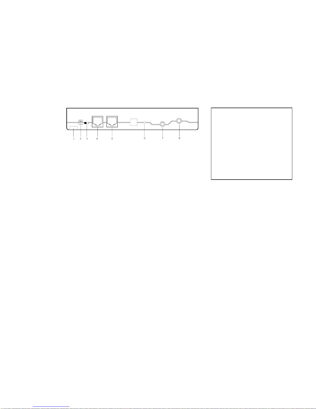
1. Lock Hole
For physically locking down the unit to deter theft.
2. Power Jack
Use the original power supply only –not used if PoE is used.
3. PoE Switch
Switch to PoE (Power Over Ethernet) if PoE is to be used.
4. LAN1
LAN jack #1 (PoE if applicable). Two LAN jacks are provided: LAN1 is for the logger and LAN2 is
for the user PC (if any). This way both the logger and the PC can share a single Ethernet connection.
5. LAN2
LAN jack #2 for the user PC (if any).
6. Internal Microphone Sensitivity Adjustment
7. Hook Sensor Jack
The optional Hook Sensor allows the logger to automatically start/stop recording when the handset
goes off-hook/on-hook. The Hook Sensor consists of a magnetic switch and a small magnet. The
magnetic switch is to be mounted on the phone base, and the magnet somewhere nearby but on the
handset. When the handset is lifted up, the magnetic switch opens and the logger starts recording.
When the handset is put back, the magnetic switch closes and the logger stops recording.
8. External Record Indicator Jack
The optional External Record Indicator lamp, with a 1.8 meter cable, is usually mounted on top of an
office cubicle so that the supervisor can easily see whether the agent is on the phone or not.
1. Lock Hole
2. Power Jack
3. PoE Switch
4. LAN1 (PoE)
5. LAN2 (to PC)
6. Internal Microphone
Sensitivity Adjustment
7. Hook Sensor Jack
8. External Record
Indicator Jack
Rear View
8
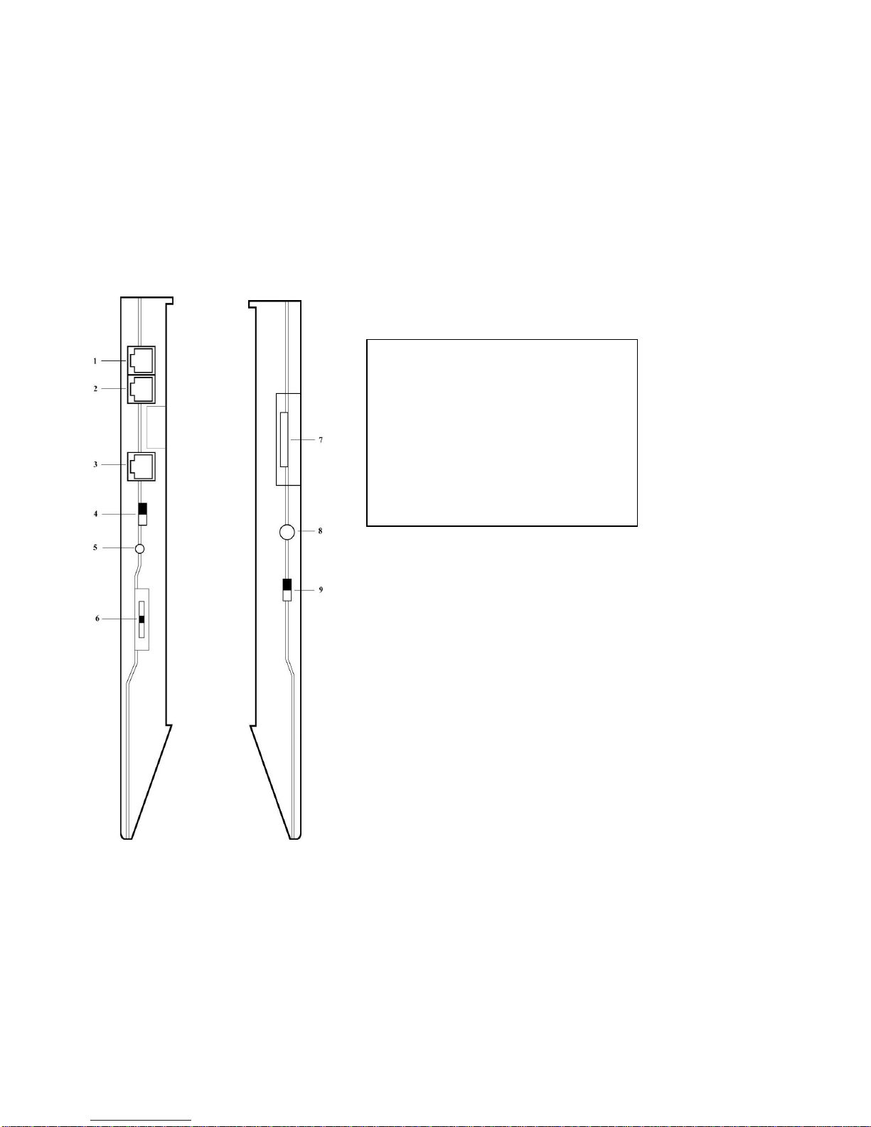
Left side Right side
1. Phone Jack
2. Handset Jack
3. Headset Jack
4. Handset Microphone Gain
5. Headset Microphone Gain
6. Headset Speaker Gain
7. SD Card Slot & Reset Button
8. Earphone Jack
9. Record Mode Switch
Side Views

9
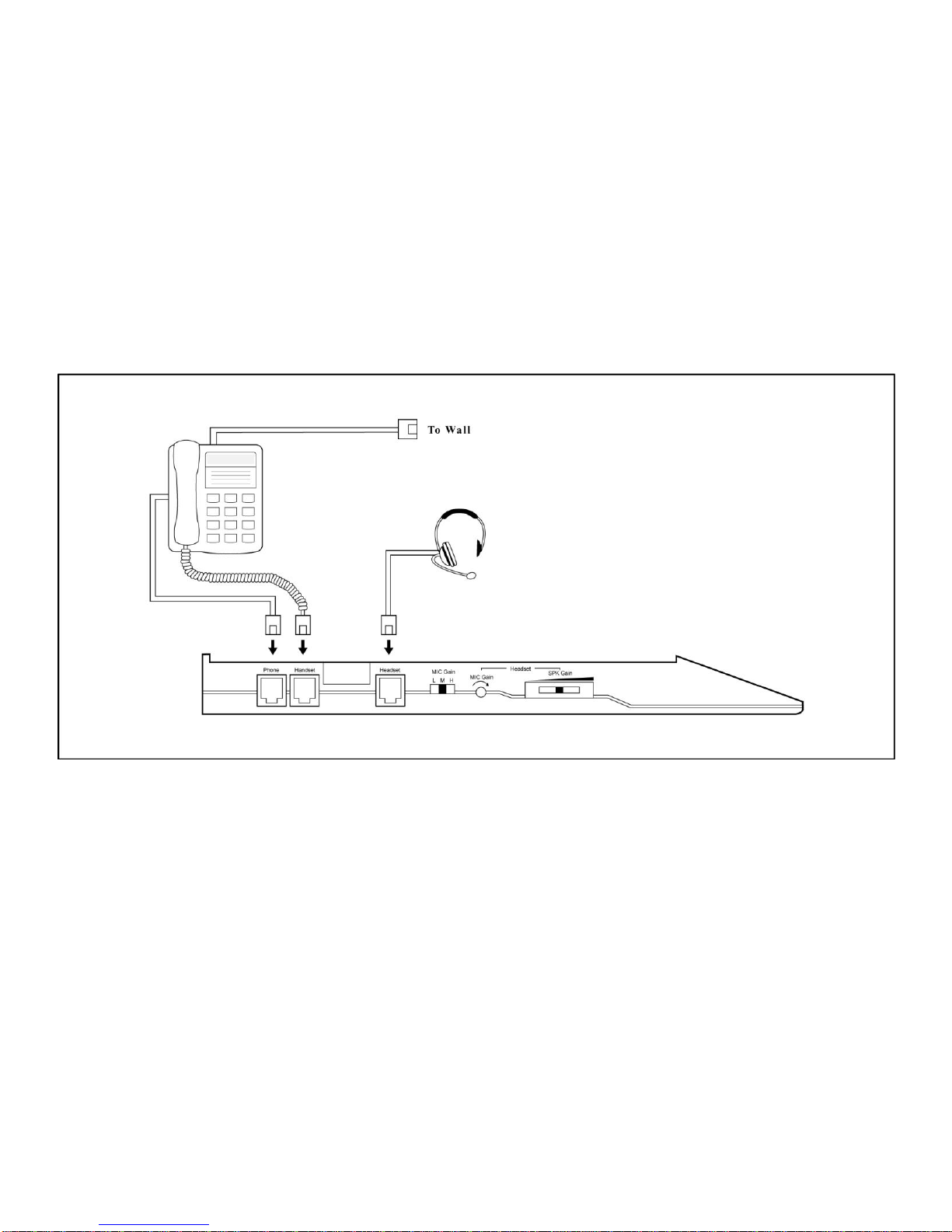
1. Phone Jack
Unplug the handset cord from the phone base. Connect this jack to the phone base using the short
phone cord supplied,
2. Handset Jack
Following the step above, plug the handset cord in here.
3. Headset Jack
If a headset is to be used, plug it in here and set the Handset/Headset Switch to ‘ He adset’.
4. Handset Mircophohe Gain
The settings are Low/Medium/High. It is for recording only and does not affect the listening volume.
5. Headset Microphone Gain
Turn the little potentiometer clockwise/counter-clockwise to increase/decrease the gain. It is for
recording only and does not affect the headset listening volume.
6. Headset Speaker Gain
A slider for adjusting the headset listening volume. It does not affect the recording level.
7. SD Card Slot & Reset Button
Remove the cover to access the SD card and the Reset Button.
To remove the SD card, push it once to pop it out.
To reset the logger, see Hardware Reset below.
8. Earphone Jack
An earphone can be optionally plugged in here to monitor the phone conversation in real time, or
the file playback.
9. Record Mode Switch
Select either Manual or Auto. Auto includes Auto-VOX and Auto-HookSensor to be further defined
by Auto Mode Control in the configuration.
10
3. Telephone/Headset Connection Diagram

11
4. System States and Key Definitions
System States
There are five different system states: Idle, Standby, Record, Playback and Setting.
Idle State
The Idle State is what the logger powers up into. The logger is idle and the Record LED is off. In this
state, the user can:
- Adjust the speaker volume.
- Select the file to play.
- Select and delete files.
- Display current free memory amount.
- Enter the Record State by pressing the Record Key (Manual Mode).
- Enter the Standby State by pressing the Record Key (Auto Mode).
- Enter the Playback State by pressing the Play/Pause Key.
- Enter the Setting State by pressing the Setting Key.
If the Auto Mode is enabled, the system will automatically exit the Idle State and enter the Stand by state
if no keys are pressed for 30 seconds.
Standby State
Applicable to the Auto Mode only, the Standby State indicates that the logger is ready to start recording.
In this state the Record LED is solid green, and the user can:
- Enter the Idle State by pressing the Record Key –the Record LED will turn off.

12
Record State
The Record State is entered either automatically (Auto Mode) or by pressing the Record key (Manual
Mode). It is the state when recording is going on. The Record LED is either solid red (Need Confirmation
disabled) or blinking red (Need Confirmation enabled). In this state, the user can:
- End recording by pressing the Stop Key (Manual Mode).
- Mark/unmark the file by pressing the Mark Key.
- Confirm recording by pressing the Record Key (if Need Confirmation is enabled).
Playback State
The Playback State is the state when playback is going on. In this state, the user can:
- Fast forward or fast rewind.
- Jump to the beginning or the end of the file.
- Jump to the previous or the next file.
- Pause, resume and end the playback.
- Mark and unmark files.
- Change the speaker volume.
When the Stop Key is pressed to end playback, the system goes back to the Idle State.
Setting State
In the Setting State, the user can:
- Set system configuration items such as date and time.
- Get the firmware version.
- Format an SD card prior to usage.
The system automatically goes back to the Idle State if no keys are pressed for 30 seconds.

13
Key Definitions
[Key]
short press of the key
[L_Key]
long press of the key
Note: The same key may function differently in different system states.

14
Record State Key Definitions
Key
Function
[]
Stop recording (Manual Mode)
[Mark]
Mark /Unmark file
User confirm (Auto Mode with Need Confirmation)
The Stop Key is used to stop recording in the Manual Mode. It has no effect in the Auto Mode.
If Auto Mode with Need Confirmation is enabled, the Record LED will be blinking red while the logger is
recording. In this case the Record Key must be pressed (turning the Record LED solid red) in order for the
file to be saved.

15
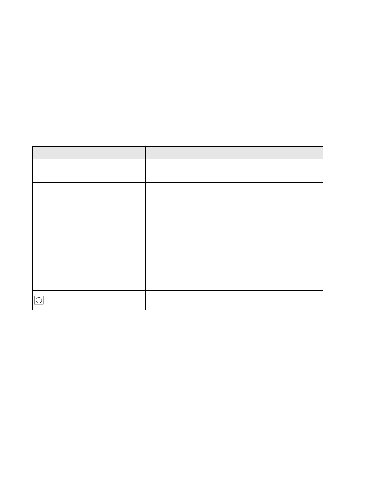
Playback State Key Definitions
Key
Function
[]
Beginning of file
[]
End of file (actually a few seconds before the end)
[][]
Previous file
[][]
Next file
[II]
Play/Pause
[]
Stop
[Mark]
Mark / Unmark file
[L_]
Fast rewind
[L_]
Fast forward
[]
Increase speaker volume
[]
Decrease speaker volume
[L_]
Keep increasing speaker volume
[L_]
Keep decreasing speaker volume
16
Idle State Key Definitions
Key
Function
[]
Previous file
[]
Next file
[L_]
Repeat []
[L_]
Repeat []
[]
Increase speaker volume
[]
Decrease speaker volume
[L_]
Keep increasing speaker volume
[L_]
Keep decreasing speaker volume
[Delete][Delete]
Delete current file (marked files will not be deleted)
[L_Delete][L_Delete]
Delete all files (marked files will not be deleted)
[]
Show free memory amount
Start recording (Manual Mode)
Enable/Disable auto recording (Auto Mode)
If Auto Mode is enabled, the system will go from Idle State to Standby State if either the Record Key is
pressed or no keys are pressed for 30 seconds.

17
Setting State Key Definitions for Item Selection
Key
Function
[]
Next item
[]
Previous item
[L_]
Repeat []
[L_]
Repeat []
[]
Next 10 items
[]
Previous 10 items
[L_]
Repeat []
[L_]
Repeat []
[Setting]
Switch to Item Edit
No keypress for 10 seconds
Exit Setting State

18
Setting State Key Definitions for Item Edit
Key
Function
[]
Move cursor left
[]
Move cursor right
[]
Increase value
[]
Decrease value
[L_]
Repeat []
[L_]
Repeat []
[Setting]
Switch to Item Selection
No keypress for 10 seconds
Exit Settings State

19
5. Configuration Settings
ID
Name
Value Range
Default
01
Logger ID
001~999
001
02
Current Year
2013~2100
03
Current Date MM:DD
MM (month) 01~12, DD(day) 01~31
04
Current Time HH:MM
HH (hour) 00~23, MM (minute) 00~59
05
Recording Quality
01 = LP (low)
02 = SP (medium)
03 = HQ (high)
02
06
Playback Volume
0~9
5
07
Recording Gain (local)
0~10 (in 3 db increments)
5
08
Recording Gain (remote)
0~10 (in 3 db increments)
5
09
Recording AGC
0 (disabled), 1 (enabled)
1
10
VOX Stop Delay (second)
1~5
4
11
VOX Sensitivity
1 (most sensitive) ~ 9 (least sensitive)
6
12
Minimum File Length (second)
1~60
1
13
Maximum File Length (minute)
1~60
30
14
IP Address Octet 1
0~255
192
15
IP Address Octet 2
0~255
1

20
16
IP Address Octet 3
0~255
168
17
IP Address Octet 4
0~255
100
18
Subnet Mask Octet 1
0~255
255
19
Subnet Mask Octet 2
0~255
255
20
Subnet Mask Octet 3
0~255
255
21
Subnet Mask Octet 4
0~255
0
22
Lock Mode
0 (disable), 1 (enable)
0
23
Unlock Password
0000~9999
1111
24
Keypress Sound
0 (disable), 1 (enable)
1
25
Disk Full Override
0 (disable), 1 (enable)
0
26
Time Stamp Announcement
0 (disable), 1 (enable)
0
27
Auto Mode Control
0 (disable), 1 (enable)
0
28
Trace Back (5 seconds)
0 (disable), 1 (enable)
0
29
Need Confirmation (Auto Mode )
0 (disable), 1 (enable)
0
30
Firmware Version
0000~9999 (read only)
31
System Command
1: Restore Default Settings
2: LCD Test
3: SD Card Format
4: Signal Meter
Most configuration items can also be viewed/changed on a PC with a web browser if the logger is
connected to the network. Refer to the Network Access section for more information.
Table of contents
Other Eletech Recording Equipment manuals


