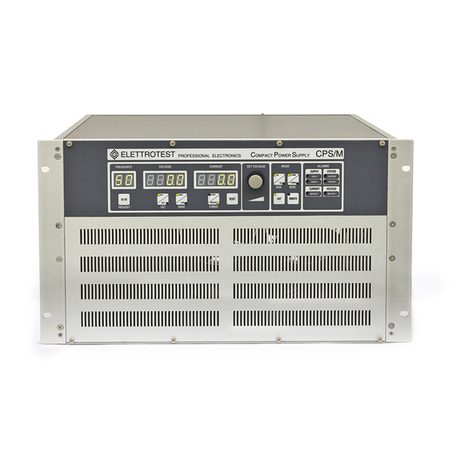
Elettrotest RM30A/2 User manual

EN
22/08/22 User Manual Resistance Meter 30A/2 –60A/2 –80A/2 62000640_08_ 2
RESISTANCE METER Models covered in this manual:
Model
Code
RESISTANCE METER RM30A/2 Portable
99150020
RESISTANCE METER RM30A/2 Rack
99150030
RESISTANCE METER RM60A/2 Portable
99150035
RESISTANCE METER RM60A/2 Rack
99150040
RESISTANCE METER RM80A/2 Rack
99150045
This manual is written from Resistance Meter revision 00_
Please check the latest manual version at www.elettrotestspa.it
To consult older manual versions, please contact our support at

EN
22/08/22 User Manual Resistance Meter 30A/2 –60A/2 –80A/2 62000640_08_ 3
Document list:
This manual is completed by a list of documents, useful to understand all the features of your
Resistance Meter.
Scan the QR-code or click on the link to directly download the documents.
Documents
Description
Link
QR-code
User Manual
Latest manual version
Manual
Brochure
Brochure
Brochure

EN
22/08/22 User Manual Resistance Meter 30A/2 –60A/2 –80A/2 62000640_08_ 4
Elettrotest Spa
P,zza R.Riello 20/B
45021 Badia Polesine (RO)
Italy
+39 042553567
www.elettrotestspa.it
After sale support
service@elettrotestspa.it
Thank you for purchasing the RESISTANCE METER.
RM30/2, RM60/2 and RM80/2 are professional instruments which allows to measure the stator
windings resistance of three-phase or single-phase motors, or of another alternating load during
the working.
Responsibility:
Elettrotest disclaims any responsibility for damage to people or things
caused by an improper use of its products.
Mandatory
-Verify voltage, power and frequency compatibility between Resistance Meter range and
electrical specification of equipment under test (EUT).
-Electrical components of the system must be suitable for the rated voltage and current of
RESISTANCE METER model
-The electrical components, which by construction cannot support external influences,
can only be used on condition that adequate additional protection has been provided
with automatic disconnection protection.
Notes:
This manual lists precautions and information about operating procedure of device.
The content of this manual is subject to change without prior notice because of continuing
improvements on the instrument’s
Should you have any questions or find any error please contact us by email.
Copying or reproducing all or any part of the contents of this document is strictly
prohibited, without Elettrotest permission
Version:
This manual is written for Resistance Meter version 00_ and higher.

EN
22/08/22 User Manual Resistance Meter 30A/2 –60A/2 –80A/2 62000640_08_ 5
SAFETY WARNINGS
The manufacturer urges users to read the user manual for our products before installation.
The installation must be carried out by qualified technical staff. The non-observance of the
warnings in this manual can cause electric shocks, even fatal ones.
Please find some general safety warnings below.
•This equipment must be connected to the mains supply using the appropriate safety
devices.
•RESISTANCE METER must be connected to safety ground through the correct connections.
The non-observance or the degradation of this earth connection can lead to electric
shocks, even fatal ones. As regards the correct connection modes, please refer to the
information contained in paragraph 4.
•Disconnect RESISTANCE METER from the mains before any work on the equipment and on
the connected power loads.
•Before touching the load or the output connector make sure that the power supply on the
device has been disconnected for at least 5 minutes. This is the time necessary in order for
the capacitors inside the device to discharge. The non-observance of this discharge time
can lead to electric shocks, even fatal ones.
•Avoid heavy shocks to the equipment (especially during transport) or exposure to extreme
weather conditions.
•Any damage to the product due to transportation, incorrect installation or improper use is
not covered by the guarantee supplied by the manufacturer.
•Do not use the equipment in explosive environments or in the presence of dust, acids or
corrosive and/or inflammable gases.
•Tampering with or dismantling any component in the equipment will void the warranty
automatically.
•Do not operate or store under conditions where condensing may occur or where
conductive debris may enter in the case.
•Keep the ventilation holes on the front and rear free from obstruction.
•Do not make dielectric strengths test on the input or output of the equipment. Contact
Elettrotest if you need to do specific test
ELECTRIC RISK
There are dangerous voltages inside RESISTANCE METER and over the output
connector.
The non-observance of the warnings suggest in this manual can lead to electric
shocks, even fatal ones.
OVERHEATING RISK
In the case of a ventilation system failure, the internal parts of the resistance meter
may reach high temperatures (in some cases higher than 70°C).

EN
22/08/22 User Manual Resistance Meter 30A/2 –60A/2 –80A/2 62000640_08_ 6
DISPOSAL
INFORMATION FOR USERS ON THE CORRECT HANDLING OF WASTE
ELECTRICAL AND ELECTRONIC EQUIPMENT (WEEE)
In reference to European Union directive 2012/19/EU issued on 24 July 2012 and the related
national legislation, please note that:
•WEEE cannot be disposed of as municipal waste and such waste must be collected and
disposed of separately;
•the public or private waste collection systems defined by local legislation must be used. In
addition, the equipment can be returned to the manufacturer at the end of its working life
when buying new equipment;
•the equipment may contain hazardous substances: the improper use or incorrect disposal
of such may have negative effects on human health and on the environment;
•the symbol (crossed-out wheeled bin) shown on the product or on the packaging and on
the instruction sheets indicates that the equipment must be disposed of separately;
•in the event of illegal disposal of electrical and electronic waste, the penalties are specified
by local waste disposal legislation.

EN
22/08/22 User Manual Resistance Meter 30A/2 –60A/2 –80A/2 62000640_08_ 7
INDEX
1. INTRODUCTION............................................................................................................................8
1.1. MAIN FEATURES ....................................................................................................................8
1.1.1. Resistance Measurement...............................................................................................8
1.1.2. Function VOLT................................................................................................................8
1.1.3. 4-Wires...........................................................................................................................9
1.1.4. Delay / Hold /Range function.........................................................................................9
1.1.5. Remote Control..............................................................................................................9
1.2. MODELS...............................................................................................................................10
1.3. Interface Panels...................................................................................................................11
1.3.1. Front Panel...................................................................................................................11
1.3.2. Rear Panel ....................................................................................................................11
2. INSTALLATION............................................................................................................................12
2.1. GENERAL NOTES..................................................................................................................12
2.1.1. INSPECTION..................................................................................................................12
2.2. POWER CABLING .................................................................................................................12
2.2.1. Three-Phase load (Motor)............................................................................................12
2.2.2. Single-Phase load (Motor) ...........................................................................................13
2.3. Sense Cabling.......................................................................................................................14
2.3.1. Measurement at 2-Wires.............................................................................................14
2.3.2. Measurement at 4-Wires.............................................................................................15
2.3.3. Output Connector Description.....................................................................................16
3. SERVICE AND MAINTENANCE ....................................................................................................17
3.1. MAINTENANCE / CLEANING................................................................................................17
4. GUARANTEE ...............................................................................................................................17
5. REVISION INDEX .........................................................................................................................17

EN
22/08/22 User Manual Resistance Meter 30A/2 –60A/2 –80A/2 62000640_08_ 8
1. INTRODUCTION
RM30/2, RM60/2 and RM80/2 are professional instruments which allows to measure the stator
windings resistance of three-phase or single-phase motors, or of another alternating load during
the working.
In this way it is possible to measure the temperature variation of the load under testing through
the following simple formula:
t =
Where: ∆t = over rising temperature
R1 = test beginning resistance
R = test end resistance
t1 = test beginning ambient temperature
t2 = test end ambient temperature
α= temp. Coefficient (αcu = 234.5)
1.1. MAIN FEATURES
1.1.1. Resistance Measurement
The resistance meter, as mentioned before, is capable of measuring the winding resistance of a
working single-phase or three-phase motor/load.
In case of a three-phase load, the instrument supplies the digital reading of the total resistance
between two of the three phases U, V, W, by allowing to choose, through proper commutator,
between the couple U-V and the couple U-W. This allows to measure, especially in case of not
symmetric windings, the different heating without discontinuing the test for wiring changing.
In case of capacitor single-phase motor, the same commutator allows to choose between the
reading of the main and auxiliary phase resistance.
1.1.2. Function VOLT
A working condition (commutator on VOLT) is foreseen in which the load is directly fed and the
instrument measures the input voltage between the two phases.
The choice of this position is requested when, for example during the motor starting, high current
peaks may occur, higher than the limits allowed by the instrument.
R2–R1
——— (+ t1) - ( t2- t1)
R1

EN
22/08/22 User Manual Resistance Meter 30A/2 –60A/2 –80A/2 62000640_08_ 9
1.1.3. 4-Wires
Resistance Meter allows the measurement at four wires of the load resistance, which allows to
take the measurement on loads far from the instrument avoiding that itself results faulty.
This type of measure necessitates only three ulterior connections (SENSE contact-plugs) of small
section and, in the case of wrong connection, a LED at the base of the display visualizes the
presence of it.
1.1.4. Delay / Hold /Range function
With the DELAY commutator it is possible to choose the time of response of the RM, adapting it to
the various demands, decreasing the disturbances to the measure caused from the pulsating loads
like for example the motors for compressor.
The HOLD function, insertable with proper commutator, allows to memorize the last measure
taken.
Acting on the commutator OHM RANGE it is possible to choose among four values of span: 2, 20,
200, 2000 ohm (on request extended range 20÷20000 ohm).
1.1.5. Remote Control
A rear connector allows the interface of the instrument with cards of I/O. Both an analog signal
proportional to the read value and the suitable signals to characterize the scale to which it refers
are present on that connector. It should be remarked that the analog output is completely
insulated from the circuit of measure through optical digital coupling. From the outside it is
possible to control, through this connector, both the choice of the phase to measure (UV-UW) and
the modality of measure (OHM-VOLT).

EN
22/08/22 User Manual Resistance Meter 30A/2 –60A/2 –80A/2 62000640_08_ 10
1.2. MODELS
The following tables show all the characteristics of all RESISTANCE METER codes:
RESISTANCE
METER 30A/2
RESISTANCE
METER 60A/2
RESISTANCE
METER 80A/2
DIMENSION / WEIGHT
Height
147 mm
190 mm
190 mm
Widht
257 mm
320 mm
320 mm
Depth
262 mm
360 mm
360 mm
Weight
10 Kg
15,2 Kg
15,5 Kg
Rack Units
3
4
4
GENERAL
User Interface
Analog interface
Communication Interface
RS232
Communication Protocol
Elettrotest, SCPI
Protections
Input Fuses
Resistance Range f.s.
2-20-200-2000 Ω
Voltage Range f.s.
500 Vrms
Instrument Precision
0,5% f.s.
Digital visualisation
3 ½ digits
Insulation
2000Vcc for 60s
INPUT
Input Voltage(2)
230Vac ± 10% 1PH
Input Frequency
50-60Hz
MEASURE LIMITS
Voltage limit
500 Vrms
Current Limit
30Arms
60Arms
Analog Output
5Vcc f.s. –5mA max.
f.s stands for full scale; s.v. stands for set value

EN
22/08/22 User Manual Resistance Meter 30A/2 –60A/2 –80A/2 62000640_08_ 11
1.3. Interface Panels
1.3.1. Front Panel
1.3.2. Rear Panel
RETRO/REAR of RM60A/2
FRONTALE/FRONT of
RM60A/2
RANGE
DELAY
2
20
200
2000
RANGE
DELAY
2
20
200
2000
HOLD
HOLD
ON
OFF
ON
OFF
RHM 1
RHM 2
LINE
ON
OFF
LINE
220 VAC
FUSE 0.5 A
OUTPUT
SENSE
OUT
RHM 1
OUT
RHM 2
INJECTION
INJECTION
SENSE
U
W
V
RHM1
RHM2
INPUT MAX 6A
FOR 2000 Ω
INPUT MAX 60A
FOR 200 Ω
FUSE 6A
FUSE 6A

EN
22/08/22 User Manual Resistance Meter 30A/2 –60A/2 –80A/2 62000640_08_ 12
2. INSTALLATION
2.1. GENERAL NOTES
2.1.1. INSPECTION
After unpacking the product, please inspect any damage that may have occurred during the
shipment. Save all packing materials in case the product has to be returned one day. If any
damage is found, please file a claim with the carrier immediately. Do not return the product to the
factory without obtaining the prior Return Merchandise Authorization (RMA) acceptance from
ELETTROTEST S.P.A.
2.2. POWER CABLING
2.2.1. Three-Phase load (Motor)
U
V
W
LINE
FUSE
0.5 A
OUTPUT
OUT
RHM 1
OUT
RHM 2
SENSE
INJECTION
RHM1
SENSE
INJECTION
RHM2
INPUT MAX 6A
INPUT MAX 60A
U
V
W

EN
22/08/22 User Manual Resistance Meter 30A/2 –60A/2 –80A/2 62000640_08_ 13
THREE-PHASE LOAD (MOTOR):
: In this case the reading is influenced by two windings of the load.
For symmetrical load: resistance of phase = ½ read resistance.
: In this case the reading is influenced from all three windings of the load.
For symmetrical load: resistance of phase = 3/2 read resistance.
2.2.2. Single-Phase load (Motor)
SINGLE PHASE LOAD (Motor)
Only two phases are used.
For single-Phase motor with capacitor:
-Commutator on UV: Measurement of the main phase.
-Commutator on UW: Measurement of the auxiliary phase.
F
N
LINE
FUSE
0.5 A
OUTPUT
OUT
RHM 1
OUT
RHM 2
SENSE
INJECTION
RHM1
SENSE
INJECTION
RHM2
INPUT MAX 6A
INPUT MAX 60A
U
V
W

EN
22/08/22 User Manual Resistance Meter 30A/2 –60A/2 –80A/2 62000640_08_ 14
2.3. Sense Cabling
2.3.1. Measurement at 2-Wires
In case a high accuracy of the measure is not requested, the contact-plugs of SENSE may be
bypassed with the correspondent contact-plugs of OUTPUT.
This configuration is advisable only with loads of high internal resistance (2000 ohm of span),
becoming in this case inconsiderable the resistance of the wirings.
LINE
FUSE
0.5 A
OUTPUT
OUT
RHM 1
OUT
RHM 2
SENSE
INJECTION
RHM1
SENSE
INJECTION
RHM2
INPUT MAX 6A
INPUT MAX 60A
U
V
W
LINE
FUSE
0.5 A
OUTPUT
OUT
RHM 1
OUT
RHM 2
SENSE
INJECTION
RHM1
SENSE
INJECTION
RHM2
INPUT MAX 6A
INPUT MAX 60A
U
V
W

EN
22/08/22 User Manual Resistance Meter 30A/2 –60A/2 –80A/2 62000640_08_ 15
2.3.2. Measurement at 4-Wires
In this configuration the measurement is not influenced by the wiring resistance to the load.
LINE
FUSE
0.5 A
OUTPUT
OUT
RHM 1
OUT
RHM 2
SENSE
INJECTION
RHM1
SENSE
INJECTION
RHM2
INPUT MAX 6A
INPUT MAX 60A
U
V
W

EN
22/08/22 User Manual Resistance Meter 30A/2 –60A/2 –80A/2 62000640_08_ 16
2.3.3. Output Connector Description
RHM DESCRIPTION OUTPUT CANNON 25 POLES FEMALE
1- common measure ohm/volt
2- n.c.
3- n.c.
4- n.c.
5- n.c.
6- n.c.
7- n.c.
8- n.c.
9- command range 2Kohm output 15Vdc
10 - command range 20-ohm output 15Vdc
11 - n.c.
12 - analog GND
13 - +15Vdc
14 - command measure Ω(Short circuit with pint 1 to measure Ω)
15 - n.c.
16 - n.c.
17 - n.c.
18 - n.c.
19 - n.c.
20 - n.c.
21 - n.c.
22 - command range 200-ohm output 15Vdc
23 - command range 2-ohm output 15Vdc
24 - ohm/volt analog output 5Vdc f.s.
25 - digital GND (reference command range output)
N.B. : to enable the measure of the resistance short circuit the pin1 with the pin14 with
an external contact (that support 15Vdc 50mA). With the open contact has enable
the measure of the Volts.

EN
22/08/22 User Manual Resistance Meter 30A/2 –60A/2 –80A/2 62000640_08_ 17
3. SERVICE AND MAINTENANCE
3.1. MAINTENANCE / CLEANING
Your RESISTANCE METER doesn’t need any recurring maintenance.
However, a cleaning schedule for the air filters and the fans can be optimal to keep 100%
functional your device. Cleaning frequency depends on the ambient condition.
Remember that heavily dirty filters and fans could lead to overheating problems and therefore to
machine failure.
4. GUARANTEE
The instrument is guarantee for one year in all his mechanical and electronic components.
Naturally are not admitted handlings not anticipated in the present handbook.
The instrument has consigned complete of CERTIFICATE of CALIBRATION, that guarantees the
integrity of the same.
Such document must accompany the apparatus in case of periodic verification always.
5. REVISION INDEX
Elettrotest Spa is committed to a program of continuous improvement of products and
information to the customer.
Therefore, the company reserves the right to make changes to the documentation and
specifications without notice and assumes no responsibility for any incorrect information.
Rev.
Date
Descriptions
08_
31/01/22
Typo correction –General Review
07_
15/12/08
Specification of cannon 25 Poles
06_
01/12/08
Upgrade Models 20A to 30A

ITA
22/08/22 User Manual Resistance Meter 30A/2 –60A/2 –80A/2 62000640_08_ 2
Modelli RESISTANCE METER trattati in questo manuale:
Model
Code
RESISTANCE METER RM30A/2 Portable
99150020
RESISTANCE METER RM30A/2 Rack
99150030
RESISTANCE METER RM60A/2 Portable
99150035
RESISTANCE METER RM60A/2 Rack
99150040
RESISTANCE METER RM80A/2 Rack
99150045
Questo manuale è scritto per le versioni dalla Rev.00_.
Controlla sempre l’ultima versione del manuale sul sito
www.elettrotestspa.it
Per consultare manuali di versioni precedenti, contatta il supporto
Elettrotest: se[email protected]

ITA
22/08/22 User Manual Resistance Meter 30A/2 –60A/2 –80A/2 62000640_08_ 3
Lista Documenti:
Questo manuale è completato da un elenco di documenti utili per comprendere tutte le
caratteristiche del vostro RESISTANCE METER.
Scansiona il QR-code o clicca sul link per scaricare direttamente i documenti di cui hai bisogno.
Documents
Description
Link
QR-code
User Manual
Ultima versione del manuale utente
Manual
Brochure
Brochure
Brochure
This manual suits for next models
7
Table of contents
Languages:
Other Elettrotest Measuring Instrument manuals
Popular Measuring Instrument manuals by other brands

DAKOTA ULTRASONICS
DAKOTA ULTRASONICS ZX-3 Operation manual
Hanna Instruments
Hanna Instruments HI 86301 instruction manual

Sekonic
Sekonic DIGITALMASTER L-758DR operating manual
AFRISO
AFRISO HMS operating instructions
Tektronix
Tektronix TRCP0300 user manual

Blue-White
Blue-White Sonic-Pro T-Track installation guide


