Elgas miniELCOR SCR1 User manual

GAS-VOLUME CONVERSION DEVICE
miniELCOR
Device Description
Operation Manual
Technical Description
Mounting instructions
Device settings
Single-channel conversion device of gas volume at measurement conditions to
volume at base conditions. Approved for installation in potentially explosive
atmospheres.
January 2010
Rev. 6g
PRELIMINARY

Safety Measures
This measurement device can be operated only by an operator trained in
compliance with the technical terms, safety regulations, and standards. It is
necessary to consider any other legal and safety regulations stipulated for special
applications. Similar measures also apply for special applications. Similar measures
also apply for using the accessories. The operator training must be in compliance
with Decree no. 50.1978 Coll.
The information in this manual does not have the burden of a legal obligation from the
manufacturer’s side. The manufacturer reserves the right to implement changes. Any
changes in the manual or in the product itself can be performed at any time without any
previous alert, with the goal of improving the device or fixing any typographical or technical
mistakes.

TABLEOFCONTENTS
1Introduction.............................................................................................1
1.1Basicdevicedescription........................................................................................1
1.2Functionprinciple..................................................................................................2
1.3Devicedimensions.................................................................................................7
2Devicetechnicaldescription.....................................................................7
2.1Devicearchitecture...............................................................................................7
2.2Devicepowersupply.............................................................................................8
2.3Securitymarks.....................................................................................................11
2.4Productlabel.......................................................................................................13
3Safetyinstructions...................................................................................14
3.1General...............................................................................................................14
3.2Useinpotentiallyexplosiveatmospheres...........................................................14
3.3Risksofusage......................................................................................................14
3.4Specialconditionsofuse.....................................................................................15
3.5Usingdevicevariantsfordifferentgroupsofgas.................................................15
4Metrologycharacteristics........................................................................16
4.1Measuringtemperature......................................................................................16
4.2Measuringpressure.............................................................................................16
4.3Compressibilitycalculation..................................................................................17
4.4Volumemeasuringandcalculation......................................................................18
5Connectinginputsandoutputs................................................................21
5.1Inputs..................................................................................................................21
5.2Outputs...............................................................................................................25
5.3Addingofanotherpressureortemperaturetransducer......................................26
6Communicationwithdevice....................................................................29
6.1RS‐232andRS‐485interfaces..............................................................................29
6.2OpticalinterfaceIEC‐1107...................................................................................31
7Descriptionoffunction............................................................................33
7.1Measurandmarking............................................................................................33
7.2Instantaneousvalues...........................................................................................33
7.3Archives..............................................................................................................34
7.4Deviceparameterization.....................................................................................37
7.5Otherdevicefunctions........................................................................................38

7.6Securingthedeviceagainstachangeofmetrologyparameters..........................38
8Puttinginoperation................................................................................44
9Deviceoperation.....................................................................................45
9.1Keypad................................................................................................................45
9.2Menusystem.......................................................................................................46
9.3Mainmenu..........................................................................................................49
9.4Instantaneousvaluesmenu.................................................................................50
9.5Storedvaluesmenu.............................................................................................50
9.6Deviceparametersmenu.....................................................................................51
9.7Parametersettingsmenu....................................................................................52
9.8Systemdatamenu...............................................................................................53
9.9Diagnosticsmenu................................................................................................54
10Mountinginstructions.............................................................................57
10.1Mechanicalmountingofthedevice.....................................................................57
10.2Cableconnection,grounding...............................................................................61
11Accessories..............................................................................................63
11.1Assemblyaccessories..........................................................................................63
11.2Intrinsicallysafesupplysourcesforexternalpowersupply.................................63
11.3Separationandcommunicationmodules............................................................63
11.4GPRScommunicators..........................................................................................63
11.5Otheraccessories................................................................................................63
12Technicalparameters..............................................................................64
13Inexplosivenessparameters....................................................................70
14Devicesetting..........................................................................................72
14.1Standarddevicecontrolafterinstallation............................................................72
14.2DeviceconnectionwithPC..................................................................................73
14.3SettingofcommunicationbetweendeviceandPC..............................................73
14.4Passwordinthedevice........................................................................................84
15Configurationexamples...........................................................................86
15.1Deviceparametersdisplaying..............................................................................86
15.2Gasmeterconstantsetting..................................................................................86
15.3Pulseoutputssetting...........................................................................................89
15.4Analogueoutputsetting......................................................................................94
15.5Setpointsetting–limitvaluesofmeasuredquantity...........................................97

15.6Settingofexternalpowersupplyfailure.............................................................100
15.7SettingofcommunicationthroughMODBUSprotocol.......................................101
16Pressureandtemperaturesensor/transducerreplacement..................105
16.1Pressureandtemperaturesensor/transducerreplacementprocedurein
miniELCORdevice...............................................................................................105
16.2Softwaresettingsofdeviceforpropercommunicationwithnewtemperature
sensor.................................................................................................................105
16.3Softwaresettingsofdeviceforpropercommunicationwithnewpressure
transducer..........................................................................................................108
17Softwaresettingsofthedeviceforpropercommunicationwithexternal
digitaltemperature(EDT‐34)orpressuretransducer(EDT‐23)..............109
17.1Addingofdigitaltransducerintodevice’sparameters........................................109
17.2Addingofquantitymeasuredbydigitaltransducerintodevice’sarchives..........110
18Finalverificationofthedeviceafterreplacementofsensor/transduceror
addingofdigitaltransducer...................................................................111
19Whattodoifsomethingdoesnotwork................................................116
20Literature..............................................................................................119
21RelevantLiterature................................................................................119
22Software................................................................................................120
23Usedtrademarks..................................................................................120
24Listoffigures.........................................................................................121
25ListofTables.........................................................................................123

miniELCOR
1
Used symbols and definitions
Symbol Meaning Unit
AGA8-G1 ... Calculation method of gas compressibility factor
AGA8-G2 ... Calculation method of gas compressibility factor
AGA8-92DC ... Calculation method of gas compressibility factor
AGA NX-19 mod ... Calculation method of gas compressibility factor
ASC ... Accredited Service Center
BTS … Base Transceiver Station
CL 1 ... Module for realization of product output 4-20mA
CRC ... Checksum – used for data protection
CTR ... Communication protocol
DATCOM-Kx ... Some of the products of series DATCOM-K (DATCOM-
K1, DATCOM-K2, DATCOM-K3, DATCOM-K3/A,
DATCOM-K4, DATCOM-K4/A)
DLMS ... Communication protocol
DC ... Direct Current voltage
dE … addition (difference) of energy MJ
dV … addition (difference) of primary volume Vmor Vcm
3
dVb… addition (difference) of base volume m
3
dVc… addition (difference) of corrected primary volume m
3
dVm… addition (difference) of primary volume m
3
E … Energy MJ
Es … Estimated value of energy MJ
EDTxx … Digital pressure or temperature transducer EDT 23 or
EDT 34
EMC ... Electromagnetic compatibility and resistance
EMI ... Electromagnetic radiation
firmware, FW ... Software equipment loaded in the device
GOST NX-19 ... Method of gas compressibility calculation ( related with
AGA NX-19 mod) according to VNIMS directive (valid at
temperature range -23°C to +60°C)
GOST
NX-19
Hs... Combustion heat MJ/m
3
IS ... intrinsic safety, intrinsically safe
JBZ-0x ... Some of the JBZ-01, JBZ-02, JBZ-02/A products
Modbus ... Communication protocol designed by Modicon [15]
M900 ... Specific communication protocol
SGERG-88 ... Calculation method of gas compressibility factor, more
details in Chyba! Nenalezen zdroj odkazů.
SNAM ... Communication protocol
SW ... Software for PC
C ... Conversion factor -
K ... Ratio of compressibility factors (Z/Zb) -
k
p
... Gas meter constant (number of impulses per 1 m
3
) imp/m
3
N ... Number of input impulses from gas meter imp
p ... Absolute pressure at measurement conditions kPa
pb... Absolute pressure at base conditions kPa

miniELCOR
2
Notice :
This handbook issue describes device functions with firmware FW 4.xx which is
compatible with previous firmware version 2.xx. All different features will be
mentioned respectively.
Chapters describing new device features of FW ver. 4.xx are marked with (*).
Qm... Flowrate at measurement conditions ( further primary
flowrate)
m
3
/h
Qb... Flowrate at base conditions m
3
/h
T ... Absolute temperature at measurement conditions (T = t +
273.15)
K
t ... Gas temperature °C
Tb... Absolute temperature at base conditions K
V ... Volume Vmor Vc
Vm... Volume at measurement conditions (further primary
volume)
m
3
Vc... Corrected volume at measurement conditions ( volume
corrected based on correction curve of gasmeter)
m
3
Vb... Volume at base conditions (hereinafter also the
standardized volume)
m
3
Vbs ... Error volume at base conditions (hereinafter also the
error standardized volume)
m
3
Vs... Error volume at measurement conditions (hereinafter
also the error operational volume)
m
3
Vd... Difference of primary volume m
3
Vbd ... Difference of base volume m
3
Vf... Tariff pulse counter of primary volume
Vbf ... Tariff pulse counter of base volume
Z ... Compression gas factor at measurement conditions
Zb... Compression gas factor at base conditions

miniELCOR
1
1 Introduction
1.1 Basic device description
The Gas-volume conversion device miniELCOR (hereinafter only “the device”)
is a measuring instrument designed for the conversion of the gas volume measure at
measurement conditions to volume at base conditions.
The information on the gas volume passing through is measured using the
impulse outputs of the gas meter. The gas temperature and pressure are measured
by integrated converters. The device calculates the ratio of compressibility factors of
gas using standard methods or a constant value is used.
The device has been constructed and approved pursuant to the EN 12405-1
standard as a conversion device type 1 (compact system) and can be supplied as a
T, PT, or PTZ conversion device.
From safety point of view device is constructed according to EN 60079-11 like
intrinsic safe.
It is manufactured and supplied in compliance with the following European
Parliament directives:
1994/9/EC Equipment and protective systems for use in potentially explosive
atmospheres
2004/108/EC Electromagnetic compatibility
2004/22/EC Directive on measuring instruments
Device is put onto market and into usage according to above mentioned
standards and is marked with CE mark.
The device is built in a casing with sturdy plastic with IP66 protection. It is
equipped with a graphic display and a 6-button keypad. Furthermore, it has impulse
inputs for the connection of a gas meter with LF or HF impulse output and binary
inputs. Device with FW version 4.xx and higher is suitable for connection via encoder
NAMUR or SCR. If applied encoder SCR the only miniELCOR SCR1 variant is
allowed. The binary inputs can work as check inputs to check the connection with a
gas meter or can have a different function, e.g. monitoring the conditions of safety
snap locks, doors, etc. The device has 4 available outputs. These can be configured
as impulse or binary outputs, or as data outputs for the CL-1 module. When using
this module, an analog current output can be realized.
The device is powered by a lithium battery. The life cycle of the battery is 6
years in the defined work mode. In the case of a battery power supply, one can also
use the impulse outputs. An external power supply source can be used in
applications with higher demands.
The device has a data archive of the measured values with an adjustable
structure and storing period. The binary archive stores changes on the binary inputs
and the occurrence of the monitored events (limits, etc.) Error conditions are stored
in an status archive. It is possible to program the storing of important quantities and
calculations and storage of some statistical values in the daily and monthly archive.
The archive has settings for service and metrology; in case of changes of settings,
the acts influencing the device parameters are recorded. The other logs are available
as well , see more in 7.3.

miniELCOR
2
For communication with its superior system, the device has a serial interface
RS-232 and RS-485. Various communication protocols installed in the device allow
easier connection to the SCADA systems. The device cooperates with common
phone, radio, GSM, and GPRS modems, and in case of an alarm condition, it can
initiate the connection.
The device can be enhanced by one non-metrology converter for measuring
pressure or temperature. This enhancement can be performed without breaking the
official mark on an already installed device.
1) Basic configuration of the device offers following inputs and outputs:
-analog input (pressure P - metrologic channel)
-analog input (temperature T - metrologic channel)
-4x digital input DI1 to DI4 (binary, pulse); input DI1 can be used for connecting
encoder NAMUR
-4x digial output DO1 to DO4 (binary, pulse, analog)
-communication channel RS485/RS232 for communication with suprordinate
systém
-input of external power supply
-option: connection one digital pressure or temperature transmiter EDTxx (as
nometrologic) to internal bus by help expansion board KP 065 08. This
enhancement can be accomplished by end user on already installed device
without breaching of metrological seal.
2) Device variant with SCR encoder ensures following inputs and
outputs:
-The same like at basic device variant ( see ad 1) however without possibility
of connection of digital transducer EDTxx
-1x input for SCR encoder connection by means of extention board KP 065 09
The device can be configured using the supplied SW [22] for PCs. This SW also
allows the readout, display and archive of both the immediate measured values as
well as the contents of the internal device archives.
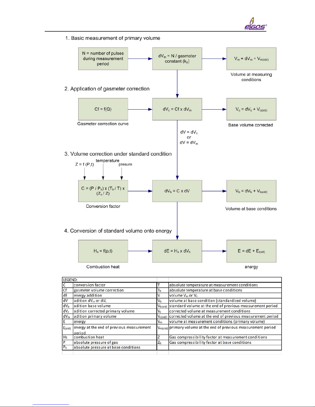
1.2 Function principle
1.2.1 Conversion using equation of state
The device obtains data on the gas flowing through via impulses (N) from an lf
or hf sensor located in the gas meter. The volume at the measuring conditions (V) is
calculated from the number of impulses (N) and gas meter constant (kp).
The device obtains other data on the gas flowing through from the temperature
and pressure converters – gas temperature (t) and absolute pressure at measuring
conditions (p). This data is used to calculate the conversion factor (C) which is
influenced also by these other factors: Absolute temperature at base conditions (Tb),
absolute pressure at base conditions (pb) and compressible factor of the gas at base
conditions (Zb).

miniELCOR
3
Volume at measuring conditions (operational volume):
V = N
kp
Ratio of compressibility factor:
K = Z
Zb
Conversion factor:
C = p * Tb*1
pb(t + 273.15) K
Volume at base conditions (standardized volume):
Vb= V * C
Gas compressibility factor expresses the deviation of properties of natural gas
from the properties of an ideal gas. By setting the parameters, it is possible to choose
a specific method for calculation of the compressibility factor pursuant to the standard
(AGA NX-19 mod, AGA8-G1, AGA8-G2, SGERG-88 or AGA8-92DC). A constant
compressibility value can be used for other gases besides natural gas. If the
pressure or temperature value gets out of the limits of validity of the chosen standard
for calculation of compressibility, the device calculates using a default compressibility
value.
The device calculates the gas flow from the impulse frequency on the input in
real time using mathematical filtration from the input signal.
Operational flow:
Q = ∆V / ∆t [m3/h]
Where: ∆V ............................ increment of operational volume
∆t ............................. time between the impulses with an accuracy
of one hundredth of a second
The value of the immediate flow displayed on the converter display is updated
every 10 seconds.
Standardized flow:
Qb= C * ∆V / ∆t [m3/h]
1.2.2 Error values of volumes at measuring conditions and
volumes at base conditions
For calculation during error conditions (i.e. in case of a converter error,
deviation of the quantity value from the working range, or device error), the device
has counters of the error volume at measuring conditions (Vs) and error volume at
base conditions (Vbs). These counters are interconnected with the pertinent counters
of volume at normal conditions.
A detailed description of device behavior during normal and error conditions is
in Article 4.4.

miniELCOR
4
1.2.3 Volume correction at measurement conditions
Device enables to compensate gasmeter error according to predefined
correction curve from gasmeter test certificate. This function and parameters Vccan
be activated only by manufacturer or by Acreditive service to ensure that used
gasmeter correction curve in dependance on flowrate Qmis valid within working
conditions.
Error of measurement is corrected by usage of function f(Qm). For corrected
volume is:
Vc = Vmx f(Qm)
where
Vc... Corrected volume at measurement conditions
Vm... Primary volume
Qm... Primary flowrate
Linear interpolation method is used for getting values between calibration
points. File with correction values is to be inserted into device with help of service
programme 22. Information about insertion of correction curve into device is logged
in setup archive.
The principle of volume calculation are seen on Fig. 1
Condition for usage of volume correction.
1. Correction is used only in case that gasmeter transmits at least 10 pulses
per second resulting in usage only HF sensors.
2. Under Qmin correction is not applied and over Qmax value of correction
coefficient given for Qmax will be used.
Conversion of volume on energy (*)
Device enables to calculate consumpted quantity of gas directly in energy form.
This conversion uses value of combustion heat Hs. Calculation is made with
adding of differences dVb( and dVbs) multiplied by actual value of combustion heat
Hs.
dE=Hsx dVb, dEs=Hsx dVbs
Two other counters ( energy counter E and estimated energy counter Es) are
dedicated for measurement in configurable energy units: MJ, kWh, Btu.
Note :
No conversion of absolute counter value (E or Es) is accomplished after
change of units. Following increases are added already respecting new units.
Principle diagram of energy calculation is drawn at Fig. 1

miniELCOR
5
Combustion heat Hs
To get correct conversion it is necessary to enter correct value of combustion
heat and relative conditions. Then device will make new conversion of relative
temperature for defined relative conditions and final value will be used for energy
calculation. In case of AGA8-92DC method combustion heat is not entered but
calculated directly from gas composition according to EN ISO 6976. For the other
methods value Hs(MJ/m3) must be entered manually and always under those
relative conditions:
combustion temperature/ temperature of gas = 25°C / 0 °C
miniELCOR
6
Fig. 1 Volume and energy calculations - Scheme

miniELCOR
7
1.3 Device dimensions
Fig. 2 Device dimensions
2 Device technical description
2.1 Device architecture
The device’s electronics are laid out on three basic boards.
The bottom part of the casing contains the board of inputs and outputs
containing the battery and back-up battery and terminal box for connecting the
pressure and temperature sensors and any device inputs and outputs. The
connections related to the metrology function of the converter are protected by
covers which are secured with official mark.
Optionally, the input board can have an extension board for connecting an
additional digital pressure (EDT 23 type) or temperature (EDT 34 type) converter.
This additional digital converter communicates with the converter using the protocol
Modbus RTU interface RS-485.
Note:
If SCR encoder is required it can be arranged only by manufacturer
or by authorised service center. Those two subjects will ensure
appropriate labelling placed on housing.

miniELCOR
8
The lid of the housing contains a processor board which is protected by a cover
and secured by an official mark. The board cover has an opening for access to the
service switch. The service switch can be use to enable/disable the setting of the
device parameters using a service SW.
Fig. 3 Main parts of the device
2.2 Device power supply
2.2.1 Supply battery
The device is powered by a built-in battery (lithium) with a voltage rating of
3.6 V. The life cycle of the battery depends especially on the configuration of the
device, the frequency of communication, and the time the display is on. The
consumed capacity is calculated during the device’s activity and the capacity
decrement is recorded in its memory. The device will issue an alert to replace the
battery 90 days before the expected discharge (error messages E9 – see Table 8.

miniELCOR
9
Defined mode with life cycle of the supply battery of more than 5 years:
•Archiving period of the data archive 1 hr
•Communication with device 2 min/day
•Showing on the display 2 min/day
•Period of input impulses ≤10 Hz
•Measuring period 15 s
•Surrounding temperature 25 °C
•expansion board KP 065 09 ( SCR encoder ) is not used
If the device is operated with higher consumption than in the defined mode, it
is necessary to count on a more frequent replacement of the battery or use a network
power source.
2.2.2 Replacement of supply battery
. It is suitable to disconnect the discharged battery as soon as possible. While
the battery is being replaced, the device does not measure pressure or temperature,
but counts the incoming lf impulses (but does not convert the number of pulses, this
will be performed only when the supply battery is connected again) and insures that
the real time clock is running. The data stored in the device archives and parameter
settings will remain preserved.
Discharged batteries belongs at hazardous waste category. According to
OEEZ (2002/96/ES) directives and and other internal directives battery must not be
disposed together with household waste. Withdrawing duty is applied over
discharged battery.
2.2.3 Back-up battery
The battery ensures the back-up of important functions in case of discharge or
replacement of the supply battery. The back-up battery can be replaced in an
accredited service center after the official and security mark is broken (replacement
can not be performed in a potentially explosive atmosphere). It is necessary to use
the same type of battery. Only recommended type of battery may be used.
Due to correct calculation of remaining battery capacity after replacement it is
mandatory to reset this information with service SW tool [22].
Replacement of battery is allowed also at hazardous zone but only with
recommended type of battery.

miniELCOR
10
Defined mode for life cycle of back-up battery of 10 years
•Storing, temperature 25 °C
•Backed-up inputs (DI1 – DI4) not connected or connected contacts
disconnected
•Does not depend on the presence of the supply battery
Defined mode for life cycle of back-up battery of 4 years
•Backed-up inputs (DI1 – DI4) short-circuited
•Without powering battery
Self-discharging of batteries
The back-up and supply batteries are lithium. Their capacity drops due to self-
discharging. The recommended time frame for their replacement is 10 years, even if
the battery was never connected.
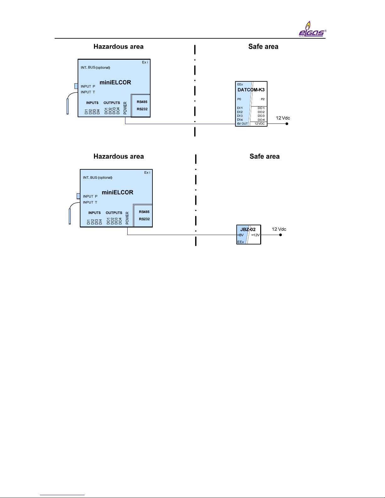
2.2.4 External power supply
Usage of external power supply is necessary in case of appliance of:
-NAMUR HF pulse input
-Binary output
-NAMUR encoder.
External power supply is recommended in case of increased current consumption
regimes like:
-frequent communicationi (more than once a day),
-frequent LCD displaying
-SCR encoder usage.
An approved intrinsically-safe source must be used for the external power
supply. In case a NAMUR type sensor is not connected to the device, one can use
the built-in sources of the communication modules DATCOM-Kx or sources JBZ-01,
JBZ-02.
If the NAMUR sensor is connected to the device, one must always use an
external power source JBZ-01 or JBZ-02.
miniELCOR
11
Fig. 4 Examples of external power supply
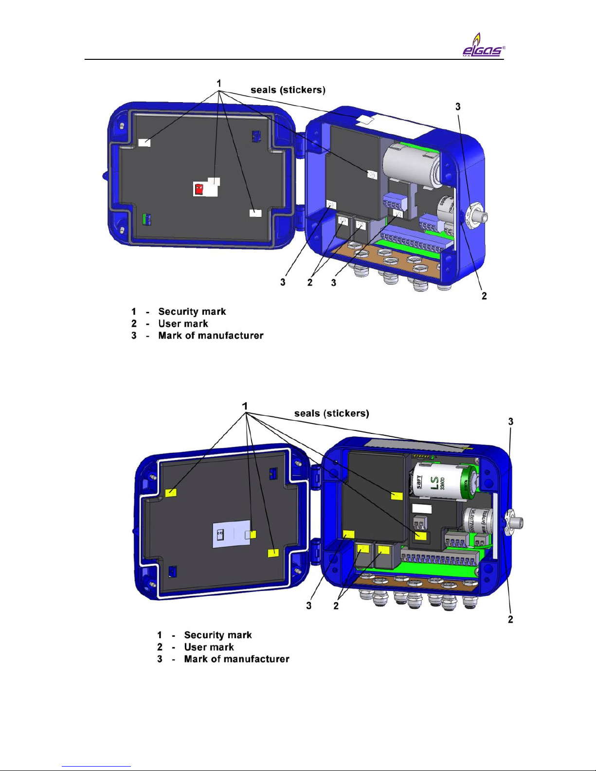
2.3 Security marks
Security marks located on the device indicate the technical condition of the
device regarding unauthorized handling.
Security mark of the manufacturer (metrology mark)
- its design is stipulated by the Approval certificate on the quality management
system for production, output control, and testing pursuant to Enclosure no. 2,
procedure D, ND no. 464/2005 Coll., issued by the Notified person no. 1383. Such
security mark has the same importance for the user as the so called Official mark
pursuant to the Act on Metrology.
In case such a mark is broken, the manufacturer does not guarantee that the
properties of the device are in compliance with the EC Certificate on type verification.
User mark
- control mark of the user (seals) as needed
Mark of manufacturer
- control mark of manufacturer as needed
miniELCOR
12
Fig. 5 Security marks (device without SCR encoder)
Fig. 6 Security marks of miniELCOR SCR

miniELCOR
13
2.4 Product label
Fig. 7 Product label English version
Fig. 8 Product label – original certification for ZONE 1
This manual suits for next models
1
Table of contents
Other Elgas Media Converter manuals

Popular Media Converter manuals by other brands

ASTRO
ASTRO U-911 operating manual

Baumer
Baumer HOG 220 Installation and operating instructions

Korenix
Korenix JetCon 1701GP-U user manual

Genie Security Solutions
Genie Security Solutions GAHD-HDMI manual

Imagine communications
Imagine communications Selenio 6800 HUC6800+C Installation and operation manual

ION
ION EZ Vinyl/Tape converter quick start guide


Polyend
Polyend Poly 2 Instructions of use

Task Lighting
Task Lighting LCDMXSD-D3-L manual

KTI
KTI KC-300DM series installation guide

Behringer
Behringer ULTRAGAIN PRO-8 DIGITAL ADA8000 user manual

CYP
CYP CPCD-3A Operation manual

Advantech Wireless
Advantech Wireless SSPBMg-C400-BRE Installation and operating manual