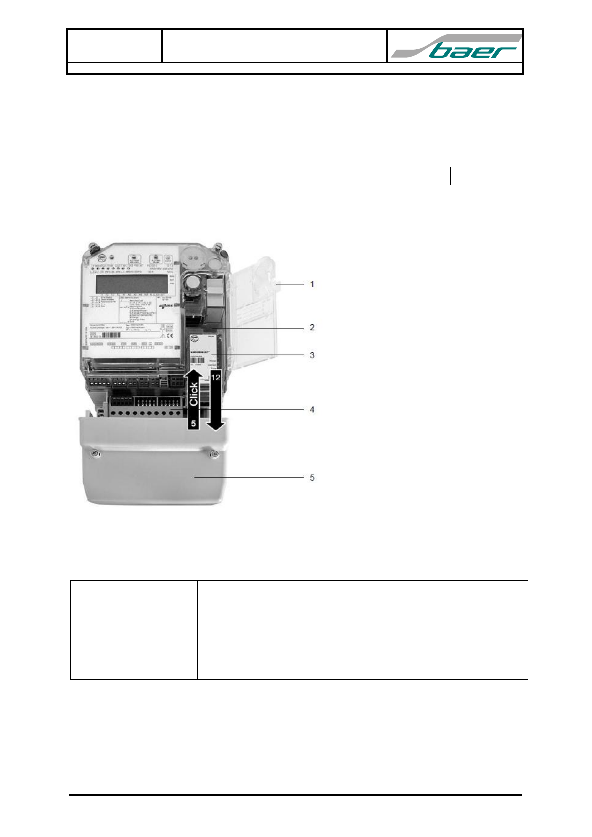
Interface Module XC Modbus
Protocol Converter / User Manual
Page 3 from 10
E120103819092
Baer Energie- & Messtechnik GmbH Siemensstr. 3 D-90766 Fürth Phone +49 911 970590 Fax +49 911 9705950
Communication (Modbus RTU, Protocol Converter)
The interface port RS485 is conforming to “Modbus Application Protocol V1.1b”: Modbus RTU
(Remote Terminal Unit).
Fixed baud rate from the 2nd electrical interface (see EMH COMBI-TOOL-Software: communication
interfaces, set please the data transmission at a fixed baud rate without baud rate changeover), data
format: 8N1;
The following rules define the protocol for information transfer between a Modbus MASTER and the
Interface Module XC Modbus:
The module supports only the “Modbus RTU Mode of Transmission”: Read Holding Registers.
Transmission settings: 8N1 (1 start bit, 8 data bits, no parity, 1 stop bit).
All communications on the RS485 bus conform to a MASTER/SLAVE scheme. In this scheme,
information and data is transferred between a Modbus MASTER device (e.g. AMR Software) and
up to 32 SLAVE devices (Modbus Interface Module XC).
The MASTER initiates and controls all information transfer on the communications loop.
A SLAVE device never initiates a communications sequence.
All communications activity on the loop occurs in the form of “PACKETS”. A packet is a serial
string of 8 bit / byte. The maximum number of bytes contained within one packet is 255.
All packets transmitted by a MASTER are REQUESTS. All packets transmitted by a SLAVE are
RESPONSES.
At most one SLAVE can respond to a single request from a MASTER.
The Modbus module supports the Function Code 3 (Read Holding Registers) with signed 32 bit
values (Signed Int32, Type D). All values includes 2 words (registers) with 16 bits each: first register
(even register addresses: 0,2,4,6...) for high-word and second register (odd register addresses:
1,3,5,7...) for low-word.
Example:
Value = 12345678Hex (32 bit := 4 Byte) start at register address 20:
:= 4660 × 65536 + 22136 = 305419896
The Modbus module uses for ID-Address the first data value in the service data list (TS): register
addresses 0 and 1. For setting the value use please the EMH COMBI-TOOL-Software.
Possible value range: 1 to F7Hex := 1 to 247Dec / Value outside of this range: ID-Address := 1 (default)
Example:
Value (ID-Address) = 0000007BHex (:= 00000123Dec) starts at register address 0: