ELGO Electronic HMIX2 Series User manual
Operating Manual
SERIES HMIX2
Magnetic Incremental Linear Encoder with 1 µm Resolution
High resolution of 1 µm
Direct contact-free measurement
High measurement accuracy
Very resistant against dust dirt and water
Periodic index pulse or free
definable reference pulse (option)
799000789 / Rev. 1 / 2019-10-01
Translation of the original operating manual


Contents
- 3 -
1Contents
1Contents ............................................................................................. 3
2General, Safety, Transport and Storage ........................................... 5
2.1 Information Operating Manual .............................................................................5
2.2 Explanation of Symbols ........................................................................................5
2.3 Statement of Warranties.......................................................................................6
2.4Demounting and Disposal....................................................................................6
2.5 General Causes of Risk........................................................................................6
2.6 Personal Protective Equipment...............................................................................6
2.7 Conventional Use ...............................................................................................7
2.8 Safety Instructions for Transport, Unpacking and Loading ..........................................7
2.9 Handling of Packaging Material ............................................................................7
2.10 Inspection of Transport ........................................................................................7
2.11 Storage .............................................................................................................7
3Product Features ................................................................................ 8
3.1 Functional Principle.............................................................................................8
3.2 Pulse Diagram....................................................................................................8
4Technical Data ................................................................................... 9
4.1 Identification ......................................................................................................9
4.2 Dimensions Sensor..............................................................................................9
4.3 Dimensions of FBK80 (guiding profile for magnetic tape BK80) ................................10
4.4 Dimensions of the End / Connection Profile AFBK80 ..............................................10
4.5 Technical Data Sensor ....................................................................................... 11
4.6 Technical Data Magnetic Tape............................................................................12
5Installation and First Start-Up......................................................... 13
5.1 Operating Area ................................................................................................13
5.2 Installation of the Magnetic Tape.........................................................................14
5.3 Installation of the Sensor .................................................................................... 18
5.4 Alignment - Sensor / Magnetic Tape ....................................................................19
5.5 Mounting Distance - Sensor / Magnetic Tape ........................................................19
5.6 Alignment HMIX2 Sensor / Magnetic Tape ............................................................ 20
5.7 Mounting the Guiding Profile FBK80 & End/Connection Profile AFBK80 .................... 22
5.8 Activation of the Sensor......................................................................................22
6Connections...................................................................................... 23
7Disturbances, Maintenance, Cleaning............................................. 24
7.1 Fault Clearance................................................................................................24
7.2 Re-start after Fault Clearance..............................................................................24
7.3 Maintenance.................................................................................................... 25
7.4 Cleaning .........................................................................................................25

Contents
- 4 -
8Type Designation ............................................................................. 26
8.1 Type Designation HMIX2....................................................................................26
8.2 Type Designation Magnetic Tape.........................................................................27
8.3 Type Designation Guide Profile ...........................................................................28
8.4 Accessories ......................................................................................................28
9Index ................................................................................................ 31
General, Safety, Transport and Storage
- 5 -
2General, Safety, Transport and Storage
2.1 Information Operating Manual
This manual contains important information regarding the handling of the device. For your own safety and operational safety, please ob-
serve all safety warnings and instructions. Precondition for safe operation is the compliance with the specified safety and handling instruc-
tions. Moreover, the existing local accident prevention regulations and the general safety rules at the site of operation have to be observed.
Please read the operating manual carefully before starting to work with the device! It is part of the product and should be kept close to the
device and accessible for the staff at any time. The illustrations in the manual are for better demonstration of the facts. They are not neces-
sarily to scale and can slightly differ from the actual design.
2.2 Explanation of Symbols
Special notes in this manual are characterized by symbols.
The notes are introduced by signal words which express the magnitude of danger.
Please follow this advice and act carefully in order to avoid accidents, damage, and injuries.
Warning notes:
DANGER!
This symbol in connection with the signal word “Danger” indicates an immediate danger for the life and health of
persons. Failure to heed these instructions can result in serious damage to health and even fatal injury.
WARNING!
This symbol in connection with the word „Warning” means a possibly impending danger for the life and health of
persons. Failure to heed these instructions can result in serious damage to health and even fatal injury.
CAUTION!
This symbol in connection with the signal word “Caution” indicates a possibly dangerous situation. Failure to heed
these instructions can lead to minor injuries or damage of property.
Special safety instructions:
DANGER!
This symbol in connection with the signal word “Danger” indicates an immediate danger for the life and health of
persons due to voltage.
Failure to heed these instructions can result in serious damage to health and even fatal injury. The operations may
only be carried out by a professional electrician.
Tips and recommendations:
NOTE!
…points out useful tips and recommendations as well as information for an efficient and trouble-free operation.
Reference marks:
Marks a reference to another chapter of this manual.
Marks a reference to another chapter of another document.

General, Safety, Transport and Storage
- 6 -
2.3 Statement of Warranties
The producer guarantees the functional capability of the process engineering and the selected parameters.
2.4 Demounting and Disposal
Unless acceptance and disposal of returned goods are agreed upon, demount the device considering the safety instructions of this manual
and dispose it with respect to the environment.
Before demounting, disconnect the power supply and secure against re-start. Then disconnect the supply lines physically and discharge
remaining energy. Remove operational supplies and other material.
Disposal:
Recycle the decomposed elements: Metal components in scrap metal, Electronic components in electronic scrap, Recycle plastic compo-
nents, dispose the remaining components according to their material consistence.
CAUTION!
Wrong disposal causes environmental damages!
Electronic scrap, electronic components, lubricants and other auxiliary materials are subject to special refuse and can
only be disposed by authorized specialists!
Local authorities and waste management facilities provide information about environmentally sound disposal.
Safety
CAUTION!
Please read the operating manual carefully, before using the device! Observe the installation instructions! Only start
up the device if you have understood the operating manual. The operating company is obliged to take appropriate
safety measure.
The initial operation may only be performed by qualified and trained staff.
Selection and installation of the devices as well as their embedding into the controlling system require qualified
knowledge of the applicable laws and normative requirements on the part of the machine manufacturer.
2.5 General Causes of Risk
This chapter gives an overview of all important safety aspects to guarantee an optimal protection of employees and a safe and trouble-free
operation. Non-observance of the instructions mentioned in this operating manual can result in hazardous situations.
2.6 Personal Protective Equipment
Employees have to wear protective clothing during the installation of the device to minimize danger of health.
Therefore:
Change into protective clothing before performing the works and wear them throughout the process.
Additionally observe the labels regarding protective clothing in the operating area.
Protective clothing:
PROTECTIVE CLOTHING
… is close-fitting working clothing with light tear strength, tight sleeves and without distant parts. It serves preliminari-
ly for protection against being gripped by flexible machine parts.
Do not wear rings, necklaces or other jewellery.
PROTECTIVE GLOVES
…for protecting the hands against abrasion, wear and other injury of the skin.
PROTECTIVE HELMET
…for protection against injuries of the head.
General, Safety, Transport and Storage
- 7 -
2.7 Conventional Use
The ELGO-device is only conceived for the conventional use described in this manual.
The HMIX2 - ELGO- length measuring system only serves to measure lengths and distances.
CAUTION!
Danger through non-conventional use!
Non-intended use and non-observance of this operating manual can lead to dangerous situations.
Therefore:
Only use the device as described
Strictly follow the instructions of this manual
Avoid in particular:
Remodelling, refitting or changing of the construction or single components with the intention
to alter the functionality or scope of the device.
Claims resulting from damages due to non-conventional use are not possible.
Only the operator is liable for damages caused by non-conventional use.
2.8 Safety Instructions for Transport, Unpacking and Loading
CAUTION!
Transport the package (box, palette etc.) professionally. Do not throw, hit or fold it.
2.9 Handling of Packaging Material
Notes for proper disposal: 2.4
2.10 Inspection of Transport
Check the delivery immediately after the receipt for completeness and transport damage.
In case of externally recognizable transport damages:
Do not accept the delivery or only accept under reserve.
Note the extent of damages on the transportation documents or delivery note.
File complaint immediately.
NOTE!
Claim any damage immediately after recognizing it. The claims for damage must be filed in the lawful reclaim peri-
ods.
2.11 Storage
Store the device only under the following conditions:
Do not store outside
Keep dry and dust-free
Do not expose to aggressive media
Protect from direct sun light
Avoid mechanical shocks
Storage temperature (4) needs to be observed
Relative humidity (4) must not be exceeded
Inspect packages regularly if stored for an extensive period of time (>3 months)

Product Features
- 8 -
3Product Features
The HMIX2 is an incremental magnetic length measuring system. The sensor technology and translator circuit
are placed in the same small housing. The magnetic tape can also be fixed into a guiding rail by using the pro-
vided adhesive tape. The HMIX2 can be installed up to a maximum distance of 0.8 mm to the magnetic tape.
Overview of the features:
Wear-free, magnetic measuring principle
Direct contactless measurement
High resolution of 1 µm
Repeat accuracy ±1 µm
The distance between sensor and measuring tape can vary between 0.1 and 0.2 mm.
When using without cover tape, a mounting distance up to 0.5 mm is allowed.
With periodic index pulse output or free definable reference pulse (option)
Measuring length theoretical unlimited
Very resistant against dust, dirt and water
3.1 Functional Principle
The basis of the magnetic incremental encoders consists of a scanning technology, which scans the north and
south poles on the coded magnetic tape and produces a single Sine/Cosine wave for each pole.
The complete sine/cosine signal process is interpolated electronically. Depending on refinement of the interpola-
tion, together with the pole distance of the magnetic tape, the resolution of the measuring system is determined.
The magnetic tape (4.6) has a pole pitch of 1 mm. A special evaluation electronic (translator) processes the
sine/cosine wave into square output signals from the signal information of the magnetic tape. These square
signals are equivalent to conventional optical rotary- or linear encoder outputs.
Figure 1: Magnetic tape
3.2 Pulse Diagram
Figure 2: Pulse diagram
N N N NS S S S N N N NS S S S N NS SN NS SS
B
B‘
Z
Z‘
A
A‘
Channel A and B are phase
shifted by 90°
The index pulse Z/Z’ output
occurs periodically every 1 mm
or as a free definable reference
pulse (R / R’) when ordering
option R (8.1).
Technical Data
- 9 -
4Technical Data
4.1 Identification
The type label serves for the identification of the unit. It is located on the housing of the sensor and gives the
exact type designation (=order reference, 8) with the corresponding part number. Furthermore, the type label
contains a unique, traceable device number. When corresponding with ELGO please always indicate this data.
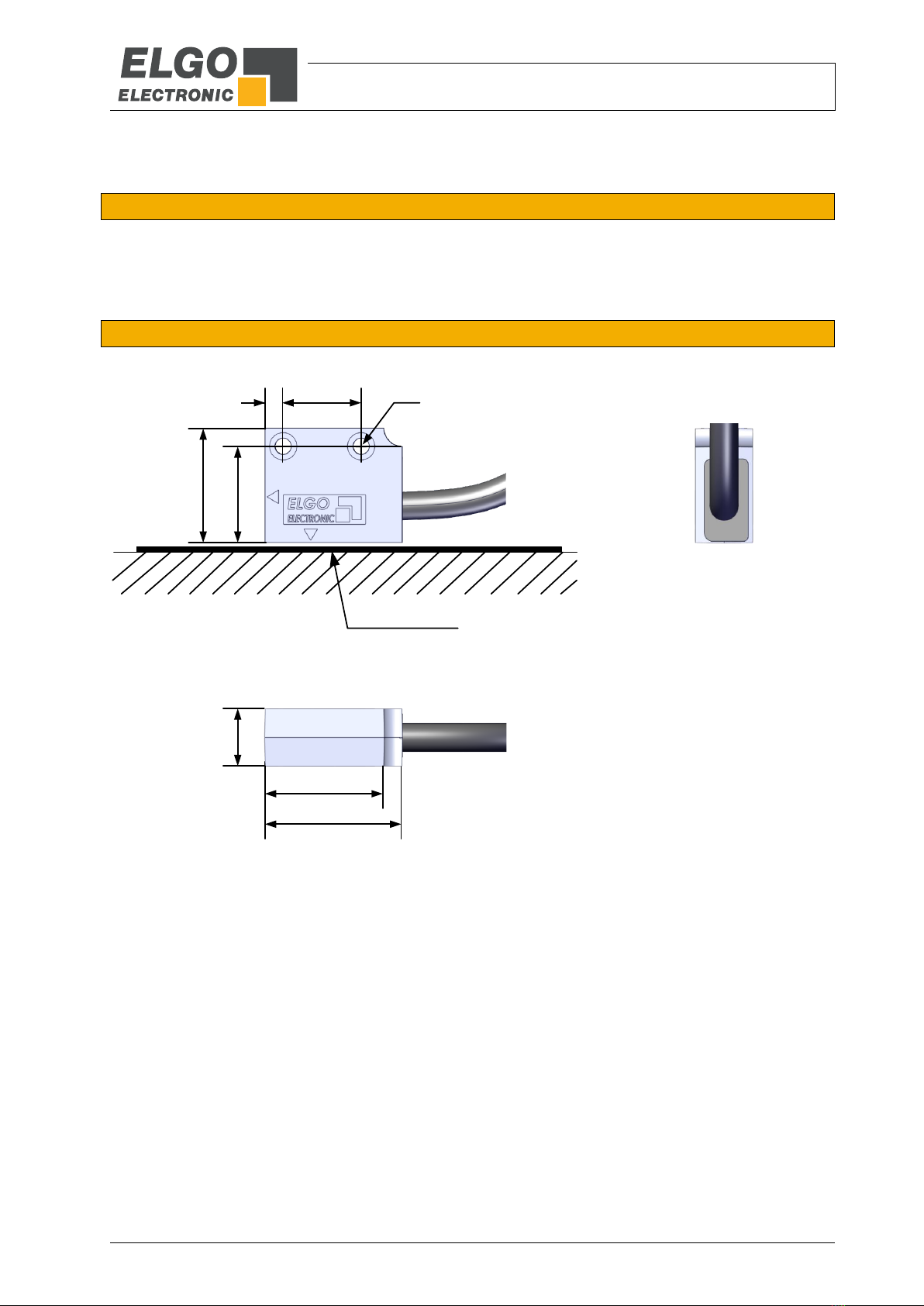
4.2 Dimensions Sensor
Figure 3: Dimensions Sensor
30
12.5
Magnetic Tape
17
4
20.5
25
24.5
Ø3.4

Technical Data
- 10 -
4.3 Dimensions of FBK80 (guiding profile for magnetic tape BK80)
Figure 4: Dimensions FBK80
4.4 Dimensions of the End / Connection Profile AFBK80
Figure 5: Dimensions AFBK 80
320 320320 20
B
Top view
Side view
B
20
4
20
10
30
40
Screw M2 x 4

Technical Data
- 11 -
4.5 Technical Data Sensor
HMIX2 (Standard version)
Mechanical data
Measurement principle
incremental
Repeat accuracy
± 1 µm
System accuracy in µm at 20° C
± (15 µm + 20 µm x L)
L= measuring length in meters
Distance sensor / magnetic tape
max. 0.2 mm resp.
max. 0.5 mm (when using without cover tape)
Basic pole pitch
1 mm
Housing material
Zinc die cast
Housing dimensions
L x W x H = 30 x 12.5 x 24.5 mm (4.2)
Required magnetic tape
Standard: MB20-10-10-1-R
Option REF: MB20-10-10-2-R-C-REFXXXX
Option BK80: MB20-10-10-1-R-D-BK80
Option BK80 + REF: MB20-10-10-2-R-D-BK80-REFXXXX
Maximum measuring length
theoretically unlimited
Connection type
open cable ends (plug connectors optionally 8)
Sensor cable
1.5 m standard length (others on request)
Sensor cable bending radius
60 mm
Maximum cable length
5 VDC / TTL = 10 m
10 … 30 VDC / HTL = 30 m
10 … 30 VDC / TTL = 50 m
Weight
approx. 35 g without cable; cable approx. 60 g/m
Electrical data
Power supply voltage
10 … 30 VDC or 5 VDC (depends on order information)
Residual ripple
10 … 30 VDC: <10 %
5 VDC: ± 25 mV
Consumption
max. 150 mA at 10 … 30 VDC
Output levels
HTL or TTL (depends on order information 8.1)
Output signals
A/A‘, B/B‘, Z/Z‘ (index pulse) resp. R/R’ (optional reference pulse),
push-pull, durable short circuit proof
System resolution
0.001 mm (at 4 edge triggering)
Index pulse
1 mm periodically or free definable reference pulse (8.1)
Output frequency per channel
1 MHz (more on request)
Output current
max. 20 mA per channel
Operational speed
max. 2 m / s
Ambient conditions
Storage temperature
-25 … +85° C
Operation temperature
-10 … +70° C
(-25 … +85° C on request)
Humidity
max. 95 %, not condensing
Protection class
IP67

Technical Data
- 12 -
4.6 Technical Data Magnetic Tape
The magnetic tape consists of two components:
The actual magnetic tape which carries the position information
A mechanical stainless steel back iron
Magnetic Tape MB20-10-10-1-R
Coding
incremental, single track system
Pole pitch
1 mm
Operation temperature installed
-20 … +65° C
(-20 … +80° C when using without adhesive tape, options „B“ or „D“)
Storage temperature uninstalled
Short-term: -10 … +60° C
Medium-term: 0 …+40° C
Long-term: +18° C
(-20 … +80° C when using without adhesive tape, options „B“ or „D“)
Gluing temperature:
+18 … +30° C
Relative humidity
max. 95 %, not condensing
Material carrier tape
Precision strip 1.4310 / X10CrNi 18-8 (EN 10088-3)
Double-faced adhesive tape
3M-9088 (observe instructions), others on request
Dimensions
without adhesive tape:
10 mm (± 0,1) x 1,35 mm (± 0,11)
with adhesive tape (excl. carrier):
10 mm (± 0,1) x 1,56 mm (± 0,13)
with adhesive tape (incl. carrier):
10 mm (± 0,1) x 1,63 mm (± 0,14)
Length expansion coefficient
16 x 10-6 1/K
Thermal length expansion
∆L[m] = L[m] x [1/K] x ∆[K]
(L = tape length in meters, ∆= relative temperature change)
Bending radius
min. 150 mm
Available lengths
32 m (up to 70 m on request)
Weight magnetic tape
ca. 62 g/m (incl. magnetic tape and cover tape)
Tape imprint
ELGO standard, printing colour black, digit height >= 5 mm
Influence of external magnets
External magnetic fields must not exceed 64 mT (640 Oe; 52 kA/m) on
the surface of the magnetic tape, as this could damage or destroy the
code on the tape.
Protection class
IP65
Installation and First Start-Up
- 13 -
5Installation and First Start-Up
CAUTION
Please read the operating manual carefully before using the device! Strictly observe the Instal-
lation instructions! In case of damage caused by failure to observe this operating manual, the
warranty expires.
ELGO is not liable for any secondary damage and for damage to persons, property or assets.
The operator is obliged to take appropriate safety measures.
The first start-up may only be performed by qualified staff that has been trained and author-
ized by the operator.
5.1 Operating Area
WARNING!
Do not use the device in explosive or corrosive environments!
The device must not be installed close to sources of strong inductive or capacitive interference
or strong electrostatic fields!
CAUTION!
The electrical connections must be made by suitably qualified personnel in accordance with
local regulations.
The device may be designed for switchboard mounting. During work on the switchboard, all
components must be de-energized if there is a danger of touching the energized parts!
(protection against contacts)
Wiring works may only be performed in the de-energized state!
Thin cable strands have to be equipped with end sleeves!
Before switching on the device, connections and plug connectors have to be checked!
The device must be mounted in a way that it is protected against harmful environmental influ-
ences such as splashing water, solvents, vibration, shock and severe pollution and the operat-
ing temperature must not be exceeded.

Installation and First Start-Up
- 14 -
5.2 Installation of the Magnetic Tape
NOTE External Magnetic Fields
The magnetic tape must not be influenced by external magnetic fields!
The magnetic tape must not come into direct contact with other magnetic fields (e.g. perma-
nent magnets, magnetic clamps, electromagnets, magnetic stands)! This may cause irrepara-
ble damage, which will compromise the measuring accuracy or even the functioning.
5.2.1 The Magnetic Tape MB20-10-10-1-R
In the standard case, the magnetic tape is delivered as described
It is installed by gluing it to the respective mounting surface.
The magnetic tape consists of 2 pre-assembled components:
A magnetized, flexible plastic tape (Pos. 3), which is connected with a magnetically conductive steel
tape as inference band (Pos. 4) and is supplied with an adhesive tape (Pos. 5).
A magnetized permeable cover tape (Pos. 1), which serves for the mechanical protection of the plastic
tape (not required for the measurement) and is supplied with an adhesive tape (Pos. 2).
Therefore a divergent tape structure and scope of delivery is also possible.
The cover tape is also available separately
Figure 6: Components of the magnetic tape
Pos. 1: Stainless steel cover tape
Pos. 2: Double-sided tape
Pos. 3: Magnetized plastic tape
Pos. 4: carrier tape stainless steel
Pos. 5: Double-sided tape
Pos. 6: Mounting surface, for example machine bed

Installation and First Start-Up
- 15 -
5.2.1 Magnetic Tape MB20-10-10-1(2)-R-D-BK80
Figure 7: Magnetic Tape MB20-10-10-1(2)-R-D-BK80
The cover tape (C) is not included in the delivery of this version.
5.2.2 Handling
In order to avoid tension in the tape, it must not be stretched, compressed or twisted.
It should be stored with the magnetized plastic tape to the outside (see Figure 8), the minimum bending radius
must be noted here
Figure 8: Handling
5.2.3 Processing hint for the gluing of magnetic tapes
Surface-Preparation: In order to guarantee optimal adhesion, all anti-adhesive contamination (e.g. oil, grease,
dust, separating agents) has to be removed using solvents with residue-free evaporation.
Suitable agents are ketones or alcohols. Typical solvents for cleaning the surface are a 50/50 isopropyl alco-
hol/water mixture or heptane. Those agents are offered by Loctite and 3M among others as surface cleaners.
When using solvents, always observe the manufacturer instructions! If the surface is copper, brass etc., it should
be sealed to avoid oxidation.
Contact-Pressure: The strength of the adhesion is directly dependent on the contact the adhesive can form with
the surface. Therefore it is important to use as much pressure as possible when gluing the tape, possibly by us-
ing aids such as draw rolls. The optimum contact pressure is 4…5 kg/cm2).
Gluing temperature: The optimal gluing temperature is between + 18° C and 30° C. Avoid colder sticking sur-
faces than + 10°C, because in this case the adhesive becomes too hard and perhaps a sufficient immediate
adhesion is hardly to achieve. After proper sticking, the stability of the connection is ensured also when the tem-
perature is below zero. The final tackiness of a sticking is from experience reached after approximately 72 hours
(at + 21° C). For gluing use only the supplied adhesive tape.
<SN XX/000000001/00000 MB20-10-10-1(2)-R-D-BK80 ELGO
10.00
8.00
1.35
Top view:
Front view:
Scale 5:1
AMagnetized plastic tape
(Magnetic tape)
Magnetically conductive steel band
(Interference band)
B
Magnetized
Plastic tape
Steel tape
Installation and First Start-Up
- 16 -
5.2.4 Cutting and Gluing
Before starting the gluing process, both the magnetic and the cover tape have to be cut to the required length
Length cover tape = measuring length + sensor length + 50mm (end caps)
NOTE!
When sticking the magnetic tape pay attention to the markings on the tape and the Sensor.
Improper installation does not provide the correct values. A already glued magnetic tape is
destroyed after the removal, and cannot be used again. Note also the direction of counting
of the measuring system
Preferably the magnetic tape should be glued close to an edge or into a groove, which
should be deep enough to embed the magnetic tape and the cover tape.
When unprotected, the cover tape may peel off!
Therefore: Use tape end caps (8.2) or let the cover tape overlap the end of the magnetic
tape and fix it with a screw.
The tape must be glued smoothly on the surface. The measuring accuracy decreases if the tape is not even!
Before gluing the magnetic tape and the cover tape onto the surface, they should be left lying on the mounting
surface for ca. 30 minutes so that the temperature matches. This prevents strain in the tape due to thermal ex-
pansion.
Mounting steps:
1. Thoroughly clean surface (5.2.3)
2. Acclimatization: let magnetic tape and cover tape adjust their temperature
3. Remove the protection foil from the magnetic tape
4. Glue magnetic tape under great pressure
5. Thoroughly clean surface of magnetic tape
6. Remove the protection foil from the cover tape
7. Glue the cover tape under great pressure
8. Safeguard the ends of the cover tape against peeling off, e.g. by using end caps (8.2)
5.2.1 Resistance against Chemical Influence
Table 1: Resistance against chemical influence
Show no or little effect in constant contact after 2-5 years:
formic acid
glycerol 93°C
linseed oil
soy beans oil
cotton seed oil
N-hexane
lactic acid
formaldehyde 40%
Iso octane
petroleum
Show weak to moderate effects in constant contact after approximately 1 year:
acetone
gasoline
acetic acid 30%
oleic acid
acetylene
steam
acetic acid, pure acetic acid
sea water
ammonia
acetic acid 20%
isopropyl ether
stearic acid 70°C, anhydrous
kerosene
Have strong effects when contacting permanently after 1-5 months:
benzene
nitric acid 70%
turpentine
toluene
lacquer solvent
nitric acid, red, vitriolic
carbon tetrachloride
tetrahydrofuran
trichloroethylene
nitrobenzene
hydrochloric acid 37%, 93°C
xylene

Installation and First Start-Up
- 17 -
5.2.2 Magnetic Tape Variants
Figure 9: Magnetic Tape Variants
Magnetic Tape with Guiding Profile FBK80
Standard BK80 - 1 track with guiding profile FBK80
Magnetic tape: MB20-10-10-1-R-D-BK80
N S N S N S N S N S N S N S N S N S N S N S N S N
Magnetic tape
Interference band
Profile FBK80
Option BK80 –REF - 2 tracks with guiding profile FBK80
Magnetic tape: MB20-10-10-2-RD-BK80-REFXXXX
Magnetic tape
Interference band
Profile FBK80
N S N S N S N S N S S N S N S N S N S N S N S NN
N S N
Standard ( 1 track)
Magnetic tape: MB20-10-10-1-R
Option REF (reference pulse, 2 tracks)
Magnetic tape: MB20-10-10-2-R-C-REFXXXX
N S N S N S N S N S N S N S N S N S N S N S N S N
N S N S N S N S N S S N S N S N S N S N S N S NN
N S N
Cover tape
Magnetic tape
Interference band
Cover tape
Magnetic tape
Interference band
Standard BK80 - 1 track (compatible with guiding profile FBK80)
Magnetic tape: MB20-10-10-1-R-D-BK80
N S N S N S N S N S N S N S N S N S N S N S N S N
Magnetic tape
Interference band
Option BK80 - REF - 2 tracks (compatible with guiding profile FBK80)
Magnetic tape: MB20-10-10-2-R-D-BK80-REFXXXX
Magnetic tape
Interference band
N S N S N S N S N S S N S N S N S N S N S N S NN
N S N
RS1 for HMIX2 option „R“ (separate reference pulse)
Reference pulse platelet: RS1(accessory)
N S N Magnetic tape
Interference band
Usable in combination with
MB20-10-10-1-R or MB20-10-10-1-R-D-BK80
Front viewTop view

Installation and First Start-Up
- 18 -
5.3 Installation of the Sensor
For mounting the sensor two M3 screws are required. Observe the tolerances stated below.
5.3.1 Mechanical Tolerances
Tolerances
Magnetic tape type
MB20-10-10-1-R
Ride height
max. 0.2 mm resp. 0.5 mm when using without cover tape
Pitch
The maximum distance of 0.2 resp. 0.5 mm must not be exceeded at any position
Yaw angle
± 5 °
Roll
The maximum distance of 0.2 resp. 0.5 mm must not be exceeded at any position
Lateral offset
± 2.5 mm, resp. ± 0.5 mm with option R (reference pulse)
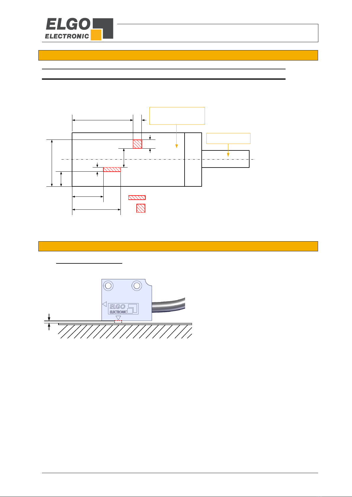
Figure 10: Tolerances
Ride height
Pitch
Yaw
±0.5°
Roll
Lateral offset
max 0.2* mm
±2.5 mm* (standard)
±0.5 mm* (option R)
max 0.2* mm
*) max 0.5 mm when using
without cover tape
*) max 0.5 mm when using
without cover tape
*) Related to the system accuracy (see
Technical Data) and 10 mm wide tape
Installation and First Start-Up
- 19 -
5.4 Alignment - Sensor / Magnetic Tape
5.4.1 Active Sensor Areas
The following drawing shows the active sensor areas of the MR sensor for measurement as well as the optionally
available reference pulse sensor (option R):
Figure 11: Active Sensor Areas
5.5 Mounting Distance - Sensor / Magnetic Tape
Figure 12: Mounting Distance - Sensor / Magnetic Tape
3.5
11.2
7.2
10.9
14.2
2
4.4
= Reference sensor (Option R)
±0.25
2
1
= MR sensor for measurement
Sensor housing
seen from above
Cable outlet
max. 0.2* mm
The entire active sensor surface must be installed
within the permitted distance to the magnetic tape.
*) max 0.5 mm when using without cover tape
Installation and First Start-Up
- 20 -
5.6 Alignment HMIX2 Sensor / Magnetic Tape
5.6.1 Alignment - Standard (without Reference Pulse)
Since the sensor housing is 2.5 mm wider than the 10 mm wide magnetic tape, make sure that the sensor co-
vers the tape far enough inwards. To do so, simply use the correct side of the sensor (see figure below) and
install it flush with the magnetic tape.
Figure 13: Alignment - HMIX2 (without Reference Pulse)
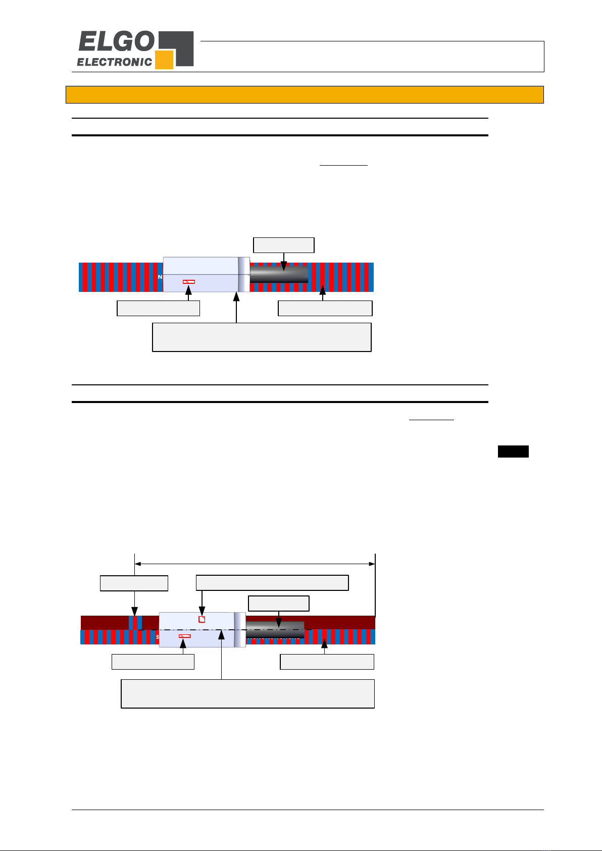
5.6.2 Alignment - Option R (Reference Pulse on Magnetic Tape Track)
If the HMIX2 is equipped with a reference pulse sensor (option "R" 8.1) and a dual track magnetic tape with a
separate reference pulse (magnetic tape option "REF"8.2) is used, both sensor surfaces must cover the corre-
sponding magnetic tape tracks correctly. This will be achieved when the sensor is precisely aligned with the cen-
ter of the magnetic tape (see figure below). The reference pulse position is indicated on the tape by a IN S NI
marker. When ordering, the reference pulse position is starting from the right side of the magnetic tape (see
example 154 mm below).
Figure 14: Alignment - Option R (Reference Pulse on Magnetic Tape Track)
Standard, without reference pulse
Required magnetic tape: MB20-10-10-1-R (single track)
N S N SN S N S N S N S
N S N SN S N S N S N SN S N SN S N S N S N S
N S N SN SN S N S N S
N S N SN SN S N S N S
N S N SN SN
fine interpolation track
active sensor area
When mounting, please just make sure that the sensor
is flush with the magnetic tape on this side.
Top view
cable outlet
With reference pulse (option R) via separate track on the magnetic tape.
Dual track magnetic tape is required: MB20-10-10-2-R-REF0154 (example)*
N S N SN S N S N S N S
N S N SN SN S N S N SN S N SN S N S N S N S
N S N SN SN S N S N S
N S N SN S N S N S N S
N S N SN SN
N
S
N
active sensor area
active area of reference pulse sensor
fine interpolation track
When mounting, please ensure that the center of the sensor
housing is precisely aligned with the center of the magnetic tape.
Top view
*) 154 mm (example)
reference pulse
cable outlet
This manual suits for next models
1
Table of contents
Popular Accessories manuals by other brands


PCB Piezotronics
PCB Piezotronics 113B03 Installation and operating manual

Honeywell
Honeywell NOTIFIER FSV-951R Installation and maintenance instructions

Cygnett
Cygnett CY2964CHCSA user manual

Hytronik
Hytronik HIM32 Installation and instruction manual

Seeley
Seeley Climate Wizard CW-P15 Installation operation & maintenance

cecotec
cecotec PURE AROMA 300 YANG instruction manual