Elmec EVduty EVCCS User manual

19378-R1
User Manual
EVduty
SMART CURRENT SENSOR
EVCCS

Table of contents
Product___________________________________________________________________________ 3
Technical specifications_____________________________________________________________ 5
Installation ________________________________________________________________________ 6
Current sensing type _______________________________________________________________ 7
Configuration
A: Conguration of the EVCCS module _________________________________________________ 8
B: Conguration of the EVdutyEVC30 charging station(s) ___________________________________ 12
C: Fonction check _____________________________________________________________________________14
Operation ________________________________________________________________________ 15
Troubleshooting __________________________________________________________________ 16
Contact us _______________________________________________________________________ 17
Limited Warranty__________________________________________________________________ 18
Figure list
Figure1: System operation __________________________________________________________ 3
Figure2: Parts description___________________________________________________________ 4
Figure3: Connections for the current sensors to the EVCCS module ____________________________ 6
Figure4: Example of an "Upstream" current sensing type ____________________________________ 7
Figure5: Example of a "Parallel" current sensing type_______________________________________ 7
Figure6: EVCCS module conguration – Create password ___________________________________ 8
Figure7: EVCCS module conguration – Main menu _______________________________________ 9
Figure8: EVCCS module conguration – Conguration_____________________________________ 10
Figure9: EVC30 charging station conguration – Access ___________________________________ 12
Figure10: EVC30 charging station conguration – Main menu________________________________ 13
Figure11: EVC30 charging station conguration – Conguration ______________________________ 14
Table list
Table1: States of light indicators _____________________________________________________ 15
Table2: Troubleshooting ___________________________________________________________ 16

3
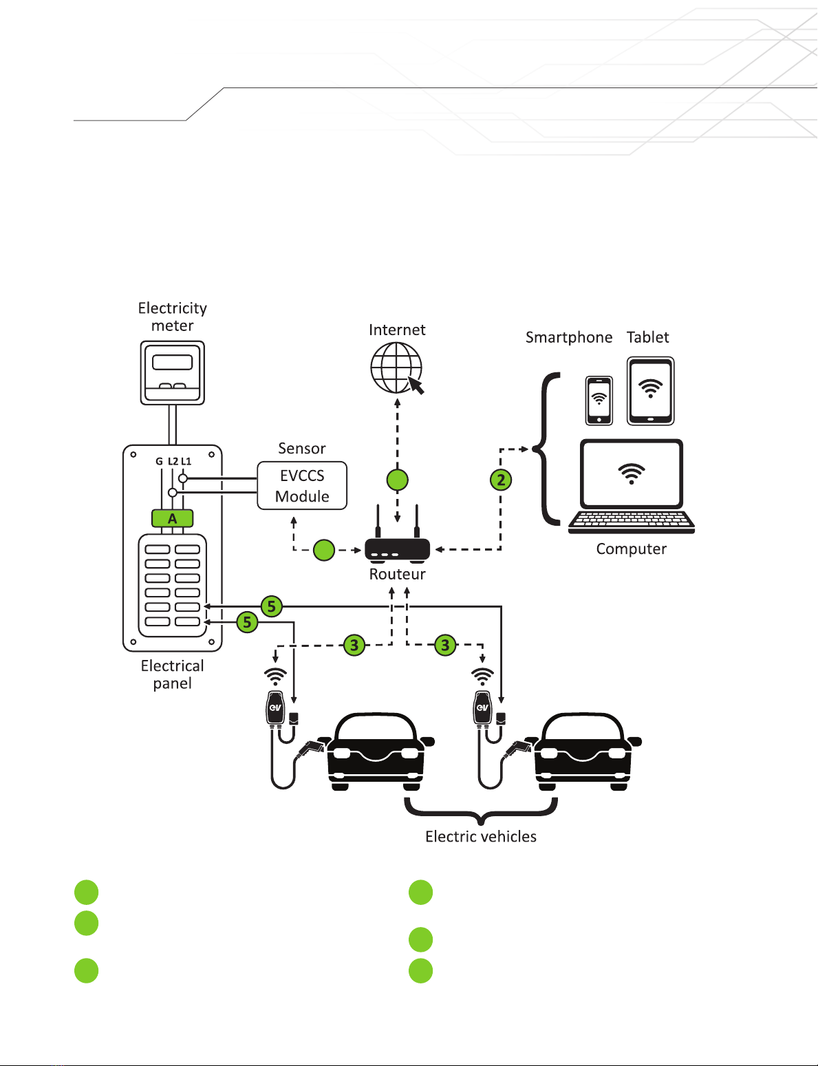
Main circuit breaker.
Connection of the EVCCS module to the local
network via WiFi or Ethernet cable.
Configuration from a computer,
tablet or smartphone.
Communication with the EVduty EVC30
charging station(s)1.
Diagnostic information and software update.
Electrical connection between the charging stations
and the electrical panel
The EVduty EVCCS is a smart current sensor that measures an electrical panel’s current consumption in real time.
The sensor sends the measured current’s information to one or more EVduty EVC30 charging stations electrically
connected to this panel. The EVC30 charging station(s) can then adjust their maximum charging current to ensure
that the electrical panel ‘s total current consumption does not exceed the limit of the main circuit breaker protecting
this electrical panel. Figure 1 illustrates the system operation.
Figure1: System operation
1: "Smart-Home" and "Smart-Pro" versions only
1
4
5
2
A 3
Product
4
1

4
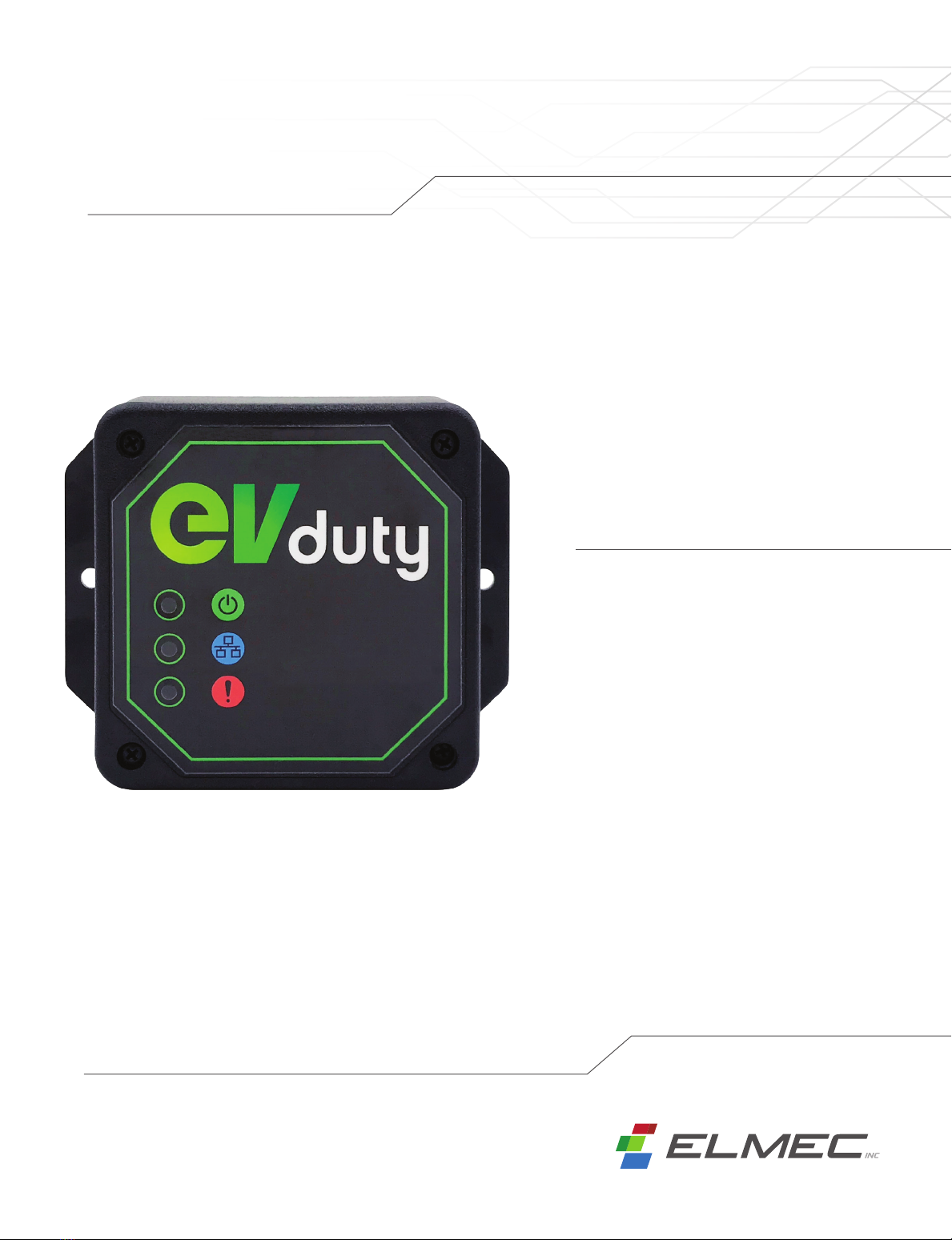
Current sensors terminal blocks
RJ45 Ethernet socket
Power port
Internal WiFi antenna
Power LED
Network communication LED
Error LED
Here is a description of the main parts of this equipment:
Figure2: Parts description
2
5
6
7
3
1
4
Product
3
5
4
6
7
2
1

5
POWER
Input voltage: 100 – 240 VAC 50/60Hz
Cable length: 1.5 m (5')
CURRENT SENSORS
Clamp-on current transformer
Opening diameter: 24.2 mm (0.95")
Dimensions: 70 mm x 44 mm (2.75" x 1.73")
Cable length: 3.05 m (10')
CURRENT READING RANGE
0-200A
OPERATING TEMPERATURE
-15°C to 40°C (5°F to 104°F)
WEIGHT AND DIMENSIONS
300 g (0.66 lb)
108mm x 852mm x 31.8mm (4.25" x 3.35" x 1.25")
COMMUNICATION
WiFi, Ethernet
Technical specications

6
Installation
1. Locate the ideal place to install the EVCCS module. This place must meet the following requirements:
• Be in a dry and temperate environment.
• Be at a reasonable distance from the electrical panel, where the current sensors will be installed.
• Be within a reasonable distance of a 120VAC power outlet.
• Allow access to the local network on which the charging station(s) is(are) connected, either by WiFi or Ethernet.
2. Secure the EVCCS module on a flat surface. (screws not included)
3. Install the two (2) current sensors on the wires/cables at the point where the current measurement is to be made.
CAUTION: This operation may require opening the main electrical panel security plate. Only qualied personnel
should perform this operation.
4. Unscrew the four (4) screws holding the cover of the EVCCS module’s casing.
Remove the cover of the EVCCS module’s casing.
5. Connect the current sensors’ wires as shown in Figure 3:
6. Reinstall the cover of the EVCCS module’s casing.
7. Connect the AC/DC power supply to the EVCCS module 5V power port.
Plug the AC/DC power supply into a 120VAC power outlet.
8. (Optional): Plug the network cable into the EVCCS module’s RJ45 Ethernet socket.
Figure3: Connections for the current sensors to the EVCCS module
Sensor #2 − White wire
Sensor #2 − Black wire
Sensor #1 − White wire
Sensor #1 − Black wire

7
Two different types of current sensing are possible.
Upstream
With this configuration, current sensors
measure the total current consumed by
all electrical equipment powered
by the main electrical panel. EVCCS
module
EVCCS
module
Charging
station
Charging
station
Other
electrical
equipment
Equivalent
electrical
equipment
Electrical panel
Electrical panel
Main circuit breaker
200A
Main circuit breaker
200A
Branch circuit breaker
40A
Branch circuit breaker
40A
Branch circuit breaker
XXA
Branch circuit breaker
40A
Parallel
With this configuration, current sensors
measure the current consumed
by an equivalent electrical equipment
(whose branch circuit breaker
has the same value as the breaker
protecting the charging station).
Current sensing type
Figure4: Example of an "Upstream" current sensing type
Figure5: Example of a "Parallel" current sensing type

8
Conguration
After completing the physical installation of the EVCCS module, you must complete the EVCCS module’s initial
configuration. Afterward, the EVduty EVC30 charging station(s) must also be configured so that they can correctly
receive the information emitted by the EVCCS module.
A: CONFIGURATION OF THE EVCCS MODULE
1. Ensure that the EVCCS module is powered. If this is the case, the "Power"LED will be lit green
and the "Network Communication"LED will flash green.
2. Using a smart device (smartphone, tablet, computer, etc.), connect to the WiFi network emitted by the EVCCS
module, which will have a name similar to "EVduty-EVCCS-XXXXX"where "XXXXX" represents the EVCCS
module’s serial number.
3. Open a web browser (e.g. Internet Explorer, Microsoft Edge, Google Chrome, Mozilla Firefox, etc.).
4. In the address bar, enter "192.168.4.1".
5. A page will appear asking to create a password (see Figure 6). Enter a password between 8 and 32
alphanumeric characters (a-z; A-Z; 0-9). This password will be requested if a reconfiguration of the EVCCS
module is required. Then, click "Submit".
Figure6: EVCCS module configuration – Create password

9
Conguration
6. A main menu will appear (see Figure 7). Click on "Configuration".
Figure7: EVCCS module configuration – Main menu

10
Conguration
7. A configuration form will be displayed (see Figure 8). Change values according to the desired configuration.
Figure8: EVCCS module configuration – Configuration
a) Channel ID
Selecting the channel ID between the EVCCS module and the EVduty EVC30 charging station(s).
Possible value: between 1 and 20
Default value: 1
NOTE: If multiple EVCCS modules are used on the same LAN, a different channel ID
must be given for each EVCCS module.
b) Current Sensing Type
Refer to the "Current sensing type" section.
Possible value: "Upstream" or "Parallel"
Default value: "Upstream"
c) Circuit Breaker Value (A)
The value of the circuit breaker protecting the circuit on which the current sensors are physically installed.
Possible value: between 10 and 200
Default value: 40

11
Conguration
d) WiFi Network SSID
(Optional) Select the WiFi network to which the EVCCS module is to connect.
Possible value: list of WiFi networks
Default value: disabled
e) WiFi Network SSID
(Optional) Manually enter the name of the WiFi network to which the EVCCS module is to connect.
Fill this box only if the target WiFi network does not appear for security reasons.
f) WiFi Network Password
(Optional) Password of the WiFi network to which the EVCCS module is to connect.
g) IP Address
(Optional) Local IP address of the EVCCS module. A value of 0.0.0.0 means that the EVCCS
module will obtain this information by DHCP.
Possible value: IPv4 address format "aaa.bbb.ccc.ddd"
Default value: 0.0.0.0
h) Default Gateway
(Optional) Default gateway of the EVCCS module. A value of 0.0.0.0 means that the EVCCS
module will obtain this information by DHCP.
Possible value: IPv4 address format "aaa.bbb.ccc.ddd"
Default value: 0.0.0.0
i) Subnet Mask
(Optional) Subnet mask of the EVCCS module. A value of 0.0.0.0 means that the EVCCS
module will obtain this information by DHCP.
Possible value: IPv4 address format "aaa.bbb.ccc.ddd"
Default value: 0.0.0.0
j) DNS Server
(Optional) DNS server of the EVCCS module. A value of 0.0.0.0 means that the EVCCS module will obtain this
information by DHCP.
Possible value: IPv4 address format "aaa.bbb.ccc.ddd"
Default value: 0.0.0.0
8. Once values have been correctly adjusted, click "Submit".

12
Conguration
B: CONFIGURATION OF THE EVDUTY EVC30 CHARGING
STATION(S)
NOTE: In order to be compatible with the EVCCS module, the EVC30 charging station’s internal software version
must be equal to or higher than "1.3.0.24-X.X.X.X".
1. Make sure the EVC30 charging station is not currently charging a vehicle. Disconnect from the vehicle if necessary.
2. Disable the EVC30 charging station’s power supply and reactivate it. This will cause the charging station to reboot,
which is necessary for the configuration.
NOTE: Following its reboot, the EVC30 charging station will emit a WiFi access point during at least 5 minutes.
The user will thus have 5 minutes to congure the EVC30 charging station. After this time, the EVC30 charging
station may stop emitting its WiFi access point.
3. Make sure the EVC30 charging station is powered. If it is, the main LED will be lit green.
4. Using a smart device (smart phone, tablet, laptop, etc.) connect to the WiFi network emitted by the EVC30
charging station, which will have a name similar to "EVduty-EVC30-XXXXX"where "XXXXX" represents
the EVC30 charging station’s serial number.
5. Open a web browser (e.g. Internet Explorer, Microsoft Edge, Google Chrome, Mozilla Firefox, etc.).
6. In the address bar, enter "192.168.4.1".
7. A page will appear asking for a username and a password (see Figure 9).
Enter "admin"for the username and "evduty"for the password. Click "Submit".
Figure9: EVC30 charging station configuration – Access

13
8. A main menu will be displayed (see Figure 10). Click "Configuration".
Figure10: EVC30 charging station configuration – Main menu
Conguration

14
Conguration
9. A configuration form will appear (see Figure 11). Change values according to the desired configuration.
Figure11: EVC30 charging station configuration – Configuration
a) WiFi Network SSID
Select the WiFi network to which the EVC30 charging station is to connect.
Possible value: list of WiFi networks
Default value: N/A
b) WiFi network SSID
(Optional) Manually enter the name of the WiFi network to which the EVC30 charging station is to connect.
Fill this box only if the target WiFi network does not appear for security reasons.
c) WiFi Network Password
Password for the WiFi network to which the EVC30 charging station is to connect. Leave this field blank
if the WiFi network to which the EVC30 charging station is to connect is not secured or open.
d) Charging Access Mode
Do not change this setting.
e) Load Shedding Function: Communication Channel ID
Channel ID between the EVC30 charging station and the EVCCS module.
Choose the same value as used in the configuration of the EVCCS module.
Possible value: between 0 and 20
Default value: 0 = disabled
10. Once values have been correctly adjusted, click "Submit".
11. If more than one EVC30 charging station is to communicate with the EVCCS module,
repeat steps 1 through 8 for each EVC30 charging station.
C: FUNCTION CHECK
In order to confirm that communication between the EVCCS module and the EVC30 charging station(s) is properly
established, check the "Network Communication" LED’s status on the EVCCS module. Refer to the "Operation" section.

15
Operation
The EVCCS module does not need any external action while it is in operation. However, the light indicators on the
EVCCS module may give useful information about the equipment's operating status.
Here is a description of the EVCCS light indicators’ possible states:
LED COLOUR STATE DESCRIPTION
Power Green
(turned off) No electric power
(lit continuously) Electric power OK
Network
communication Green
(blinks 1x) The EVCCS module is not connected to the
local network
(blinks 2x) The EVCCS module is connected to the local
network
(blinks continuously) The EVCCS module is connected to the local
network and is correctly communicating with
a EVC30 charging station
Error Red
(turned off) No error
(blinks 1x) Problem with the #1 sensor or unbalanced AC
lines
(blinks 2x) Problem with the #2 sensor or unbalanced AC
lines
(blinks continuously) The measured current is higher than the limit
allowed by the configuration
Table1: States of light indicators

16
Troubleshooting
Table 2 lists some of the most common problems as well as their causes and possible solutions.
PROBLEM CAUSE SOLUTION
"Power" LED is
not lit
The EVCCS module
is not receiving
adequate power.
Check that the power outlet in which the power supply is plugged
provides adequate voltage.
Check that the power supply unit has an output voltage of +5VDC.
"Network
communication"
LED flashes green
only once
The EVCCS module is
not properly configured
and cannot connect to
the local network.
Check parameters in the EVCCS module configuration.
If the EVCCS module is connected via an Ethernet network cable,
check the connections at each end of the cable and check the
router settings.
"Network
communication"
LED flashes green
only twice
The EVCCS
module fails to
properly connect to
at least one EVC30
charging station.
Check parameters in the configuration of the EVCCS module and
in the EVC30 charging station, specifically the "Channel ID". This
value must be configured identically for both device types.
Check that both the EVCCS module and the EVC30 charging
station are on the same local network and that this local network
allows communication from one device to another.
"Error" LED flashes
red
The EVCCS module
detects an error. See "Table 1: States of light indicators"
Main breaker
tripped
The EVCCS
module is not
properly configured.
Check parameters in the EVCCS module configuration, specifically
the "Circuit breaker value". This parameter must be identical
to the value of the circuit breaker to be protected.
The EVC30
charging station is not
properly configured.
Check parameters in the EVC30 charging station configuration,
specifically the "Channel ID". This must not be set
to "0 = disabled" in the EVC30 charging station.
The EVC30
charging station is
charging vehicles
very slowly, at a
current of about 6A
The electrical panel’s
power consumption
is very close to the
allowed limit.
None. System operating normally.
Loss or absence
of communication
between the EVCCS
module and the
EVC30 charging
station.
Check the local network to which the EVCCS module and the
EVC30 charging station are connected.
Table2: Troubleshooting

17
POSTAL ADDRESS
Service support Elmec
1141, 2eAvenue, Shawinigan
(Québec) G9T 2X9
SERVICE SUPPORT
819 533-3888
FAX
819 533-3074
EMAIL
WEBSITE
elmec.ca
Contact us

18
Limited Warranty
WHAT DOES THIS WARRANTY COVER?
This warranty covers any defects or malfunctions of your EVCCS module.
HOW LONG DOES THE COVERAGE LAST?
This warranty runs for three (3) years from the purchase date.
WHAT ELMEC WILL DO?
Elmec will repair any EVCCS module judged to have a defect or malfunction by a qualified Elmec technician. In the
event repair is not possible, Elmec will replace the EVCCS module with a new one of similar specifications and price.
WHAT DOES THIS WARRANTY NOT COVER?
Any defect caused by an abnormal use of the product.
HOW TO GET SERVICE?
To use this warranty, you must first contact the Elmec Support Service and a qualified technician
will verify if there is a real problem with the product. If it’s the case, send the EVCCS module
postage paid with a purchase proof to the following address:
ELMEC SERVICE SUPPORT
1141, 2eAvenue, Shawinigan
(Québec) G9T 2X9
Elmec will inspect the EVCCS module and contact you within 72 hours
following the product reception to tell you if the product will be repaired or replaced.
YOUR RIGHTS UNDER THE ACTUAL APPLICABLE LAW
This warranty gives you specific legal rights, and you may also have other rights which vary from
a province to another.
Table of contents
Popular Accessories manuals by other brands

Comelit
Comelit 1622 Technical manual

Enpuly
Enpuly MLG1 user manual

Zublin
Zublin Swiss Garde 360 Presence DALI Master A-Comfort... Installation instructions manual

IntelliSense
IntelliSense DT-7450 EU DUAL TEC Installation instructions and instructions for use

Baker Hughes
Baker Hughes Druck ADROIT6000 instruction manual

QuadroTech
QuadroTech QB SOCKET-1 user manual