Elite Prime Vision Polar Star Series User manual

Rev041316-DR
Ambient Light Rejecting Fixed Frame Screen
Polar
Thank you for choosing the
Elite Prime Vision,
included is our ISF certified
Polar Star
formulated for environments with minimal control over room lighting. It was designed to enhance picture
brightness, offer accurate
color fidelity, and improve contrast levels. The
educational facilities, conference rooms or any applications in which incident light is a factor.
In order for the Polar Star™
to maintain its projection qualities and o
below for proper maintenance and cleaning.
Use a dry microfiber cloth to remove dust from the screen’s surface.
When cleaning, use a damp microfiber cloth with warm water to remove any marks.
Never rub or app
ly pressure when cleaning the surface.
Never attempt to use any solutions, chemicals or abrasive cleaners on the screen surface.
In order to avoid damaging the screen, avoid touching it directly with your fingers, pens/pencils or
any other sharp or abrasive objects.
Hardware and Parts List
A. Frame Parts
x 6 pcs (4 top/bottom frame pcs + 2 side frame pcs)
B. Screen Material x
1 pc
C. Center joint
x 2 pcs
D. Elbow Joint
x4 pcs
E. Wall bracket x 4
pcs
F. wood screw
x 8 pcs
G. Hollow wall anchor
x 8 pcs
H. M5x15 screw
x 16 pcs
I. Center Support Bar x 1 -
J. Support joiner x 2 -
K. Fix Plates
x 60
www.EPVscreens.com
Ambient Light Rejecting Fixed Frame Screen
Polar
Star™ Series
User’s Guide
Elite Prime Vision,
Polar Star™ fixed frame projection screen!
Polar Star
™
, which is a reference quality front projection material precisely
formulated for environments with minimal control over room lighting. It was designed to enhance picture
color fidelity, and improve contrast levels. The
Polar Star™
is best for family rooms,
educational facilities, conference rooms or any applications in which incident light is a factor.
to maintain its projection qualities and o
ptimum performance, please refer to the list
below for proper maintenance and cleaning.
Use a dry microfiber cloth to remove dust from the screen’s surface.
When cleaning, use a damp microfiber cloth with warm water to remove any marks.
ly pressure when cleaning the surface.
Never attempt to use any solutions, chemicals or abrasive cleaners on the screen surface.
In order to avoid damaging the screen, avoid touching it directly with your fingers, pens/pencils or
any other sharp or abrasive objects.
Note:
sure all parts are
included in your
package before
pr
assemble your
Star™
projection screen.
x 6 pcs (4 top/bottom frame pcs + 2 side frame pcs)
1 pc
x 2 pcs
x4 pcs
pcs
x 8 pcs
x 8 pcs
x 16 pcs
2 pcs (depending on model/size)
4 pcs (depending on model/size)
x 60
- 180 pcs (depending on model/size)
1
The screen material
, which is a reference quality front projection material precisely
formulated for environments with minimal control over room lighting. It was designed to enhance picture
is best for family rooms,
educational facilities, conference rooms or any applications in which incident light is a factor.
ptimum performance, please refer to the list
When cleaning, use a damp microfiber cloth with warm water to remove any marks.
Never attempt to use any solutions, chemicals or abrasive cleaners on the screen surface.
In order to avoid damaging the screen, avoid touching it directly with your fingers, pens/pencils or
Note:
Please make
sure all parts are
included in your
package before
pr
oceeding to
assemble your
Polar
Star™
fixed frame
projection screen.

Rev041316-DR www.EPVscreens.com 2
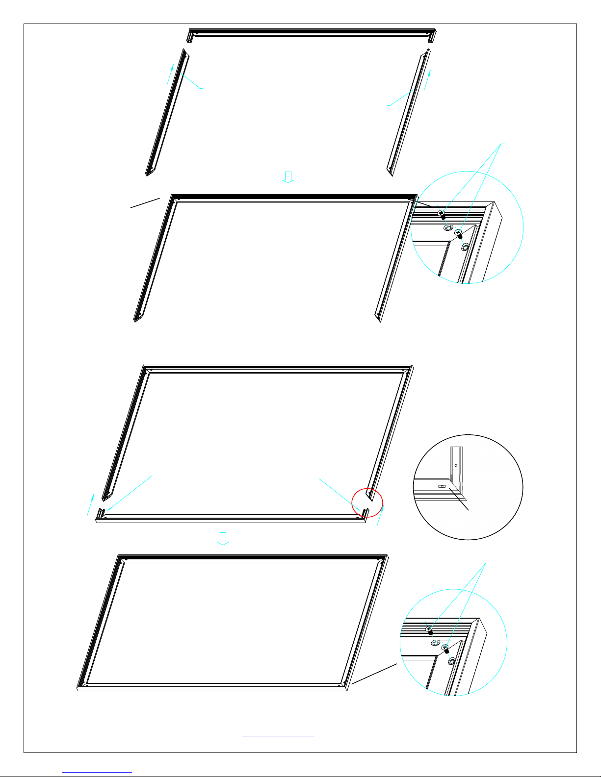
FRAME ASSEMBLY
1. Insert the center joint (c) connector to the horizontal frame piece with bevel connection and flat head,and then
fasten it with two M5x15 screws (h).
2. Insertthe other horizontal frame piece to thecenter joint connectorand then fasten it with twoM5x15 screws.
Note: a. 2 long frames should be assembled for a screen.
b. Do not tighten the screws completely until all frame pieces have been assembled correctly.
3. Insert both elbowjoint connectors into the long horizontal frame and then fasten it with twoM5x15
screws(seeFig.1).Then insert the short frames and fasten them with screws (Fig.1.2).
Push Push
Joint
Long frame
( fig.1)
Flat head
bevel connection
Bevel connection
Flat head
×2
½ Long Frame
½ Long Frame Push
Horizontal Long Frame
M5x15 Screw
M5x15 screws
M5x15 screws
Rev041316-DR www.EPVscreens.com 3
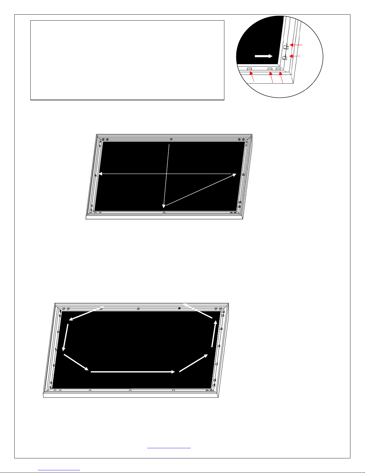
Push
Push
( fig.2)
Insert the exposed ends of the joint connectors
into the short (vertical) frame and align the four
corners so that they meet at perfect right angles
4. Join all four frame parts together following the steps shown below. (Fig.2)
Note: When assembled, please push simultaneously the two ends of the long frames.
Push
Push
Short frame
Short frame
M5x15 screws
Screw
M5
×
15Screws
Screw
(Fig.1.1)
(Fig.1.2)

Rev041316-DR www.EPVscreens.com 4
Attaching the Screen Material to the Frame
1. Make sure the screen material and frame are both lying face down on a clean, dry, and non-abrasive
surface.
2. Carefully unroll the material inside the frame. (Fig.3)
Please note the material will be noticeably smaller than the frame, as the material must be stretched to create a
sufficient amount of tension for perfect material flatness.
3. Attach the fix plates.
(1)
Stretch the material to the corner and insert the screen material’s edge in the groove of the frame. While
one hand holds the material in place the other hand snaps in the push plate (Fig.4-Fig.5).
(2) Begin by securing the four corners in the following sequence A→B→C→D (Fig.6).
(3) Insert the fix the plates as shown on Fig. 5. Fix plate ① is about 10cm away from the frame’s corner.
Fix plate ② is about 5cm away. (Fig.7)
(Fig. 6)
(Fig. 7)
Notes:
Make note of the label to help distinguish
the back and front side.
Unroll the screen material face down
Keep the screen material as close as possible
to the frame and do not allow it to scratch
against any part of the frame.
(Fig. 4)
Insert pushplate in
Screen material edge (Fig. 5)
Schematic
c
ross section of the
f
rame
Plate
Frame groove
A
B
C
D
(Fig.3)
Rev041316-DR www.EPVscreens.com 5
(4) Place a fix plate in the center of each side in the following orderE→F→G→H.(Fig.9)
(5) Next, fasten a fix plate on the center of each frame side in the following order
I→J→K→L→M→N→O→P as shown in Fig.10.
E
G
H
F
(Fig.9)
I
J
K
L M
N
O
P
Tip for attaching the last corner (D):
1. Position yourself left of location ①.
2. Pull the material to the corner of the frame with your hand while your left
hand snaps in the fix plate on location ①(the third red dot).
3. Then insert and snap in the fix plate on location②.
(Fig.10)
①
②
③
⑤
④
Pull
(Fig. 8)
Rev041316-DR www.EPVscreens.com 6
(6) Fasten the remainder of the fix plates in the empty locations in the red markings to complete attaching the screen
material. (Fig.11)
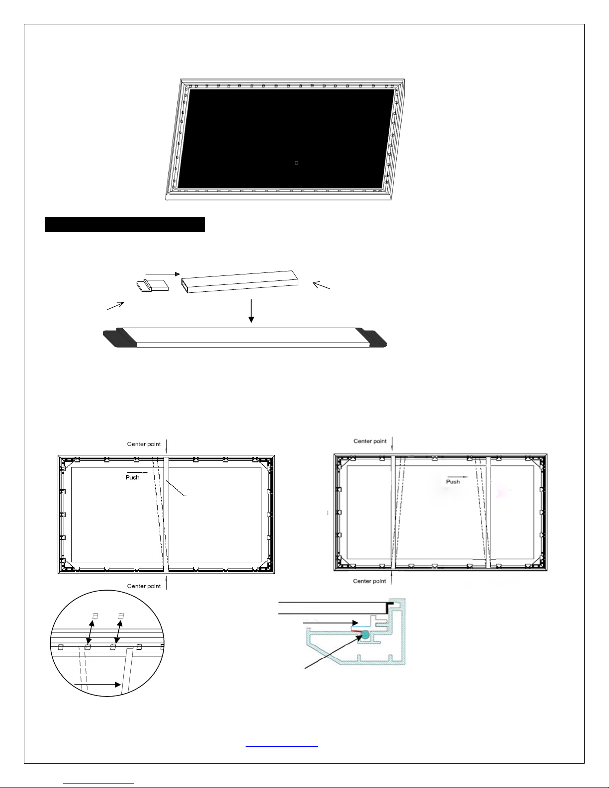
Center Support BarInstallation
1. Insert the support joiner into each end of the center support bar.
support joiner Center support bar
2. Insert the Center Support Barinto the upper top groove on the back of the frame(not the one where the fix
plate inserts) with the bottom end near the approximate center point of the frameand rotate it in at an angle so
that both ends of the bar are in alignment with the groove (see Fig. 17 below for details).
3. Slide the top end of the bar into the top center point of the frameto complete the center support bar
installation.This will provide added stability to your frame and added tension to the material.
Screen material edge
Fixed plate groove
(do not insert here)
Center Support Bar
(Fig. 17)
Remove
push
Center Support Bar
(Fig.11)
Diagonal models 135” and below use 1 x
Center Support Bar
Diagonal models above 135” require 2 x
Center Support Bars
Rev041316-DR www.EPVscreens.com 7
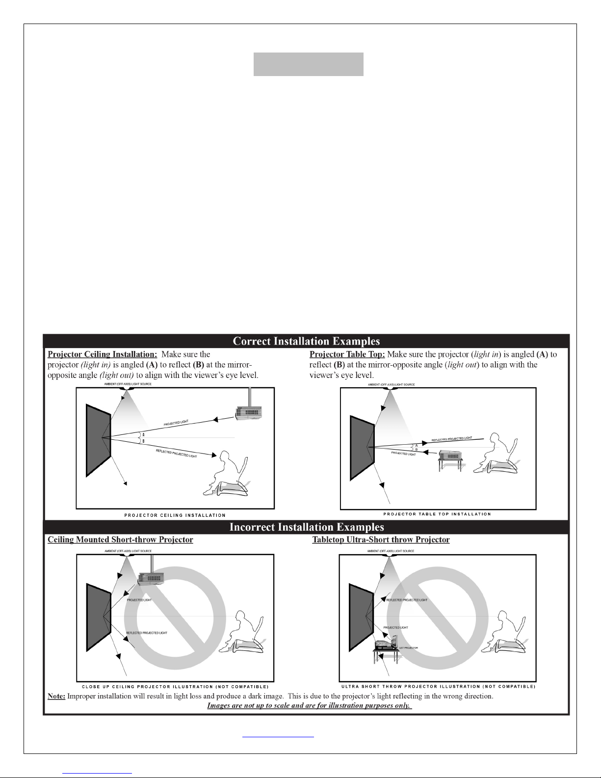
Notice to Installer:
Please use the following installation instructions to obtain superior optical performance from the
Polar Star™ Angular Reflective ALR (Ambient Light Rejecting) Screen.
•Angular-Reflective material is not compatible with ultra/short-throw projectors
•Minimum lens throw ratio 1.5x image width
•Ambient light must not come from the same direction as the projector
Since angular-reflective means that the projected image will reflect at the mirror-opposite angle, it
isimportant to position the projector so that the viewer will get the best possible image.
Step 1: Establish the general “eye level” of the viewers
Step 2: Set the appropriate projection level
Step 3: Adjust the screen height level and projection angle
Input Angle (A) = Output Angle (B) aligns with the viewer’s angle

Rev041316-DR
Installation
1.
Locate your desired installation location with a stud finder (recommended) and mark the
where the screen is to be installed
2. Drill a hole
with the proper bit size according to the wood screw
3. Line up the wall brackets
with the drilled holes on the installation location and screw them
Phillips screwdriver.
Note: Use 2 top
wall brackets on diagonal sizes
sizes 135” and above.
4.
Position the fixed frame screen o
center of the bottom frame
to secure the installation.
5. The design of the
wall brackets allow
feature of the installation design
as it allows
6.
Using both hands finish the installation by pushing the lower portion of the fixed frame screen into the
lower bracket as shown in Fig. 1
9
CAUTION
Please follow these instructions carefully to ensure proper maintenance and safety
1. When hanging the screen up, please make sure that no other objects such as power switches, outlets, furniture,
ladders, windows, etc. occupy the
space designated for your Fixed
2. Regardless if the screen is hung on or installed into the wall, make sure that the proper mounting anchors are
used and that the weight is supported appropriately by a strong and structurally sound surface j
and heavy picture frame should.
3. Frame parts are made of high quality velour
4. When not in use, cover over the screen with a furniture sheet to protect it from dirt, grime, paint or an
impurities.
5. When cleaning, use a damp soft cloth with warm water to remove any marks on the frame or screen surface.
6. Never attempt to use any solutions, chemicals or abrasive cleaners on the screen surface.
7. In order to avoid damaging the
screen, avoid touching it directly with your fingers, tools or any other sharp or
abrasive objects.
8. Spare Parts should be placed o
ut of reach of small children
For a local Elite
Prime Vision
www.EPVscreens.com
(Fig. 18)
www.EPVscreens.com
Locate your desired installation location with a stud finder (recommended) and mark the
where the screen is to be installed
.
with the proper bit size according to the wood screw
s included.
with the drilled holes on the installation location and screw them
wall brackets on diagonal sizes
below 135”, and use 3 top
wall brackets on diagonal
Position the fixed frame screen o
nto the top wall brackets as shown in Fig. 18
and push down at the
to secure the installation.
wall brackets allow
s theframe to slide
over them through its sides.
as it allows
your screen to be properly centered.
Using both hands finish the installation by pushing the lower portion of the fixed frame screen into the
9
.
Please follow these instructions carefully to ensure proper maintenance and safety
of
your
1. When hanging the screen up, please make sure that no other objects such as power switches, outlets, furniture,
space designated for your Fixed
-Frame screen.
2. Regardless if the screen is hung on or installed into the wall, make sure that the proper mounting anchors are
used and that the weight is supported appropriately by a strong and structurally sound surface j
3. Frame parts are made of high quality velour
-
surfaced aluminum and should be handled with care.
4. When not in use, cover over the screen with a furniture sheet to protect it from dirt, grime, paint or an
5. When cleaning, use a damp soft cloth with warm water to remove any marks on the frame or screen surface.
6. Never attempt to use any solutions, chemicals or abrasive cleaners on the screen surface.
screen, avoid touching it directly with your fingers, tools or any other sharp or
ut of reach of small children
in accordance with household safety guidelines.
Prime Vision
contact or Technical Support, please visit
www.EPVscreens.com
(Fig.19)
8
Locate your desired installation location with a stud finder (recommended) and mark the
drill-hole area of
with the drilled holes on the installation location and screw them
in using a
wall brackets on diagonal
and push down at the
over them through its sides.
This is an important
Using both hands finish the installation by pushing the lower portion of the fixed frame screen into the
your
Screen.
1. When hanging the screen up, please make sure that no other objects such as power switches, outlets, furniture,
2. Regardless if the screen is hung on or installed into the wall, make sure that the proper mounting anchors are
used and that the weight is supported appropriately by a strong and structurally sound surface j
ust as any large
surfaced aluminum and should be handled with care.
4. When not in use, cover over the screen with a furniture sheet to protect it from dirt, grime, paint or an
y other
5. When cleaning, use a damp soft cloth with warm water to remove any marks on the frame or screen surface.
screen, avoid touching it directly with your fingers, tools or any other sharp or
in accordance with household safety guidelines.
contact or Technical Support, please visit
Table of contents
Other Elite Prime Vision Projection Screen manuals


Popular Projection Screen manuals by other brands

Philips
Philips BDL4230E/00 Service manual

Draper
Draper Access FIT Series Installation & operation instructions

Da-Lite
Da-Lite Cosmopolitan Electrol Instruction book

Seymour Screen Excellence
Seymour Screen Excellence TAM Assembly manual

Cima
Cima Below Ceiling ElectriScreen owner's manual

Kimex
Kimex 042-3 Series installation manual

ORION Images
ORION Images R4K Series Installation and user guide

Pella
Pella architect series Service instruction

InFocus
InFocus SC-PU-60 Instruction book

Bei automation
Bei automation Laminar XL installation instructions

REMACO TECHNOLOGIES
REMACO TECHNOLOGIES PRO-L3030 manual

Derksen USA
Derksen USA GL150-MARATHON Installation and operating instructions


