Elite 600N Guide

For Power Supply Models:
600N, 2200N-A, 2200N-B, 12KN-A, 12KN-B, 12KN -C, 12KN-D
POWER SUPPLY
INSTALLATION & ADJUSTMENT
INSTRUCTIONS
Use Exclusively with FLATLITE® Electroluminescent
Lamps.
! IMPORTANT SAFEGUARDS !
When using electrical equipment, basic safety precautions
should always be followed including the following:
• This product must be installed and serviced by electrical
contractors familiar with the instructions in this manual and
local building codes.
•FLATLITE® Lamp is an electrical appliance operating at up to
280Vac.
• Do not cut or pierce without proper tools and training.
• Never power the unit from a dimmable AC source.
• Never for use in or under water.
• Never install in an accessible area without a protective cover to
prevent access.
• Do not install against an ungrounded metal surface.
• Always install in accordance with all applicable electrical
codes.
• Always disconnect power from the FLATLITE® system before
servicing.
• Equipment must be mounted securely in locations and at
heights where it will not be readily subjected to tampering by
unauthorized personnel.
• Use of any components not supplied with the FLATLITE®
system or the modification of the components supplied may
cause an unsafe condition.
• Do not use this equipment for other than its intended purpose
• This equipment is approved and rated for connection of lamps
as specified in the system design section. Never exceed the Total
or Minimum Load Rating of any power supply.
SAVE THESE INSTRUCTIONS
MAKING ADJUSTMENTS
Tools Needed:
• Phillips head screw driver
• Nonconductive blade adjustment tool
• Voltmeter capable of reading up to 400VAC RMS
• Installed Lamp size (in square inches)
• Needle-nose pliers
1. Completely disconnect Power Supply from any power source
2. If any of the optional CMD modules will be used, leave it
disconnected until the Power Supply has been fully adjusted.
3a. Models 600N, 2200N-A, B: Remove the cover from the Power
Supply and place the supply base so that the components inside
are accessible and the choke(s) are to the right.
3b. Models 12KN-A,B,C and D: Remove the access port cover
from the top of the Power Supply and place the supply so that the
opening is toward you and to the right.
4. Confirm that the input voltage select jumper is placed correctly
for your operating voltage 120 or 240VAC (See Figure 1, 2 or 3 for
jumper location). Refer to the marking on the Printed Circuit
Board (PCB). The jumper tab should connect the front two pins
for 240VAC and the back two pins for 120VAC. (Disregard this
step for Models 12KN-A,B,C,D - voltage adjusts automatically).
5. Next, match the Power Supply to the lamp size by connecting
the chokes appropriately (see specifics in Figure 1, 2, or 3. Note:
2200N-B requires no choke setup, and chokes on 12KN models
are factory set).
6. Locate the output “VOLTAGE ADJ” (white pot) and limit-
adjust “VOLTAGE LIMITING” (blue pot) potentiometers. See
Figure 1, 2 or 3 for locations. When adjusting these pots use a
NON CONDUCTIVE TOOL.
7. The blue limit pot is preset at the factory and is locked with
glue. Set up instructions for this blue limit pot are included in
case the glue has been removed or specific instructions to adjust
the pot are given from the factory. Turn the white pot all the
way counter clockwise and the blue limit pot all the way
clockwise.
E-Lite Technologies, Inc. Power Supply Instruction Manual - Page 1 of 4

8. Connect the voltmeter to the output of the Power Supply.
This can be done by inserting the probes into the back if the
lamp Molex connector or attaching it to the connection points
of the distribution wire (12KN models), prior to connection
points being insulated.
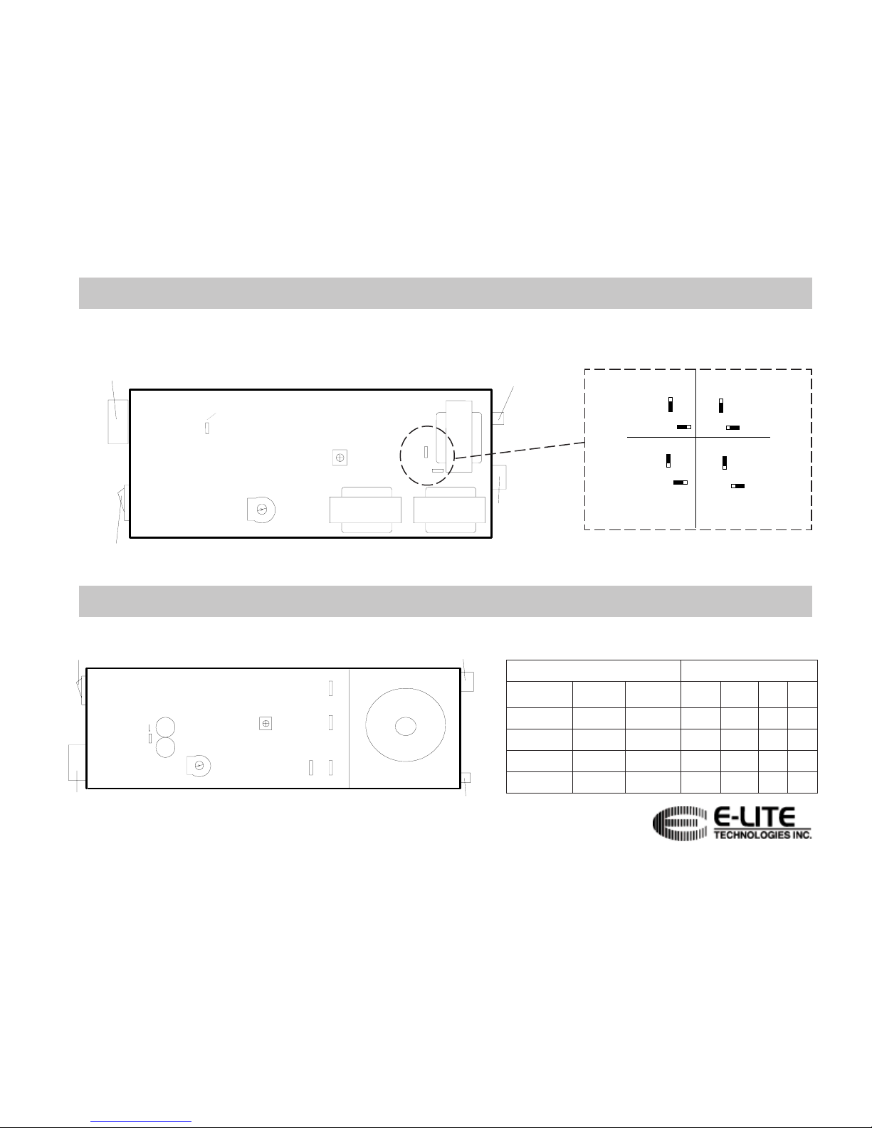
NOTE: All adjustments must be made with the lamp
connected to the Power Supply. The Power Supply must
be adjusted to TOTAL area of all lamp being connected
to an individual Power Supply. If connecting multiple
lamps, all lamps must be wired in parallel.
9. Turn on the Power Supply, the lamp should be dimly lit,
the green “Power On” LED will be lit and the voltage
should read less then 280VAC.
CAUTION: USE EXTREME CARE WHEN MAKING
ADJUSTMENTS WITH POWER ON AND COVER OFF.
10. Adjust the voltage output and voltage limit as follow:
•Turn the white pot all the way clockwise, watching
the voltmeter. The output should stay below
320VAC. If it does not, discontinue setup and check
that the Power Supply is properly sized to the lamp.
•Turn the blue pot counterclockwise until the meter
reads 330VAC.
•Turn the white output counterclockwise to the
desired voltage setting, not to exceed 280VAC.
•Allow system to stabilize for five minutes and reset
the white pot to the desired voltage or the 280VAC
limit. NOTE: At 280VAC the lamp is operating at its brightest
setting. To reduce brightness, adjusting the output lower (counter-
clockwise) until brilliance matches your requirements will increase the
life of the lamp and provide for further level of compensation.
•Turn off power and replace the cover or port access
cover.
11. At this point any CMD module can be attached and set
as desired.
12. All Models 600N, 2200N-A, B, and 12KN-A,B,C,D have
ground fault protection capability. To test this, press the
red button and the lamp will turn off. To restart the power
supply, switch the unit OFF and the ON again.
TROUBLESHOOTING
PROBLEM: LAMP DOES NOT LIGHT
1. Check that Power Supply is plugged into working outlet.
2. Check that Power Supply switch is “ON”.
3. Check the fuses.
4. Check output - check that Power Supply has been properly adjusted for the
lamp load (see Adjustment instructions, page 2).
5. If 2200N-A or B, check that the terminals mounted on E-16 and E-17 are not
touching each other or any other components on the Printed Circuit Board.
6. Check that the Lamp connection(s) to the Power Supply is (are) well made.
7. Check that the Lamp is wired correctly:
1. Turn off the power supply
2. Unplug the Lamp from the Power Supply
3. Measure across the leads with a digital multimeter to check:
a. Continuity-if continuity, there is a short in the wiring
b. Capacitance-If no capacitance, there is an open circuit in the
wiring
The problem with wiring may be in the lamp crimp attachment or in the
distribution wiring. Disconnect lamp from distribution wiring to troubleshoot.
PROBLEM: LAMP BLINKS OR FLASHES
1. Check that the Power Supply has been set to the proper input voltage.
2. Check that the power supply has been adjusted for the correct lamp load.
PROBLEM: LAMP IS DIM
1. Check that the Power Supply has been properly adjusted for the lamp load (see
Adjustment instructions, page 2).
2. If 2200N-A or B, check that the terminals mounted on E-16 and E-17 are not
touching each other or any other components on the Printed Circuit Board.
3. Check if the Lamp has been operating past it’s useful life.
4. Call E-Lite for Technical Assistance.
PROBLEM: POWER SUPPLY ADJUSTMENTS OPERATE REVERSE FROM
NORMAL
1. Check that the Lamp is within the range of the Power Supply as set.
2. Replace Power Supply with properly sized model.
PROBLEM: THE 280VAC OPERATING VOLTAGE CANNOT BE REACHED
1. Check that the Power Supply has been set to the proper input voltage (does not
apply to 12KN-A, B, C, or D).
2. Check that the Lamp is within the range of the Power Supply as set.
3. Check that the Lamp connection(s) to the Power Supply is (are) well made.
4. If 2200N-A or B, check that the terminals mounted on E-16 and E-17 are not
touching each other or any other components on the Printed Circuit Board.
5. Replace Power Supply with properly sized model.
PROBLEM: POWER SUPPLY OPERATED INTERMITTENTLY
1. Check that the Power Supply is not overheated. Relocate the Power Supply to a
cooler area or provide ventilation.
NOTE: The Power Supply has a Thermal Protection Circuit that protects the
components when the internal temperature exceeds a preset level.
E-Lite Technologies, Inc. Power Supply Instruction Manual - Page 2 of 4

ekohCsdaeL
ylppuSrewoP aerApmaL
)niqs(
aerApmaL
)mcqs( etihWeulBkcalBdeR
A-N00220001-0062546-178341E51E61E71E
A-N0022005
1-00017769-254641E61E51E71E
A-N00220081-005131611-776941E61E71E51E
B-N00220062-008147761-3161141Eenon51Eenon
ALL DRAWINGS TOP VIEW (NOT TO SCALE)
Connect chokes as follows:
For each given lamp range, set the
jumpers as follows:
voltage Limiting
VOLTAGE ADJ.
120
240 SW2
SW1
Fuses/Power Inlet
On/Off Switch
Molex Mini Fit
Connector to Lamp
6 pin CMD
connector
input voltage
select jumper
600N - figure 1
voltage
Limiting
VOLTAGE ADJ.
120
240
Fuses/Power Inlet
On/Off Switch
Molex Mini Fit
Connector to Lamp
6 pin CMD connector
E14
E15
E17
E16
CHOKE
input voltage
select jumper
2200N-A & 2200N-B - figure 2
E-Lite Technologies, Inc. Power Supply Instruction Manual - Page 3 of 4
SW2
SW1
SW2
SW1
SW2
SW1
SW2
SW1
Range 1
100-150 in
2
645-968 cm
2
Range 2
150-275 in
2
968-1774 cm
2
Range 3
275-400 in
2
1774-2581 cm
2
Range 4
400-600 in
2
2581-3871 cm
2

To determine how many chokes
are on a given power supply,
count the number of large bolts on
the bottom of the power supply.
TO ATTACH LAMP:
Lamp is connected to the Power Supply using
the twist lock connector provided. To attach
connector, align guide rib in plastic cap with
the slot on the base, slide out sleeve toward
Power Supply and twist clockwise. To
remove, push outer sleeve toward Power
Supply and twist counter clockwise
Sunlight (UV) and ambient temperature affect the
electrical characteristics of FLATLITE. Output voltage will
vary depending on these factors. Thus setting your output
voltage during the day will cause the lamp to have a different
voltage at night. Since most outdoor FLATLITE applications
are meant for a nighttime operation, it is strongly
recommended that the power supply be adjusted at
night.
(Please note: the safety of the system is not
compromised due to the compensating features of the power
supplies.)
If night time adjustment is not possible, we have
provided a chart of equivalents. This chart shows what
output voltage to set the power supply to under a variety of
conditions. For example, if 260VAC is the desired night time setting, if it is
being adjusted during a sunny, clear day at an ambient temperature of 60oF
(16oC), it must be adjusted to 75VAC. Because the voltages in the chart are
only approximate settings, it is strongly recommended that the final tuning of the
system be performed during normal system operation times.
A lamp voltage of 280VAC is the maximum allowable nighttime
setting, which in turn yields the optimum balance between maximum
brightness and lamp life. However many nighttime applications require less
brightness to achieve the desired effect as FLATLITE Lamp is a field source of
light, rather than a point source of light. There are many variables which effect
the perceived brightness of the FLATLITE Lamp in outdoor installations,
including the ambient lighting from other buildings, streetlights, etc. Further,
when lowering the lamp brightness, the life of the lamp is extended. For best
results adjust the lamp after full darkness, taking care not to exceed 280Vac.
snoitidnoc F°04<
)C°5<(
F°08<T<F°04
)C°72<T<C°5(
F°08>
)C°72>(
,ynnus,raelc
thgilyad CAV59CAV57CAV55
yduolc
thgily
ad
021
CAV CAV001CAV08
emitthgin CAV082
*XAM *CAV062*CAV042
derisedotro*
tubssenthgirb
gnideecxeton
CAV082
12KN-A, 12KN-B, 12KN-C, 12KN-D - figure 3
IMPORTANT INFO FOR OUTDOOR APPLICATIONS
rewoP
ylppuS
aerApmaL
)niqs(
aerApmaL
)mcqs(
fo#
sekohc
A-NK210053-006218522-477611
B-NK210035-001349143-000022
C-NK2
10008-008431615-869033
D-NK2100521-008754608-323054
voltage Limiting
VOLTAGE ADJ
.
Fuses
On/Off Switch
6 pin CMD
connector
CHOKE CHOKE CHOKE CHOKE
Power
Inlet
Twist Lock
Connector to
Lamp
area visible
thru access
port cover
E-Lite Technologies, Inc. Power Supply Instruction Manual - Page 4 of 4
This manual suits for next models
6
Table of contents
Popular Power Supply manuals by other brands

Hama
Hama Eco 3000 Operating instruction

Agilent Technologies
Agilent Technologies 654xA Series Service manual

PR electronics
PR electronics 5420B product manual

ICT
ICT ICT24012-20CM instruction manual

Whelen Engineering Company
Whelen Engineering Company WPPS6922 installation guide

TECSYSTEM
TECSYSTEM T412 Series instruction manual