OM-203 860 Page 5
SECTION 1 – CONSIGNES DE SÉCURITÉ – À LIRE AVANT
UTILISATION
som _nd_fre 7/02
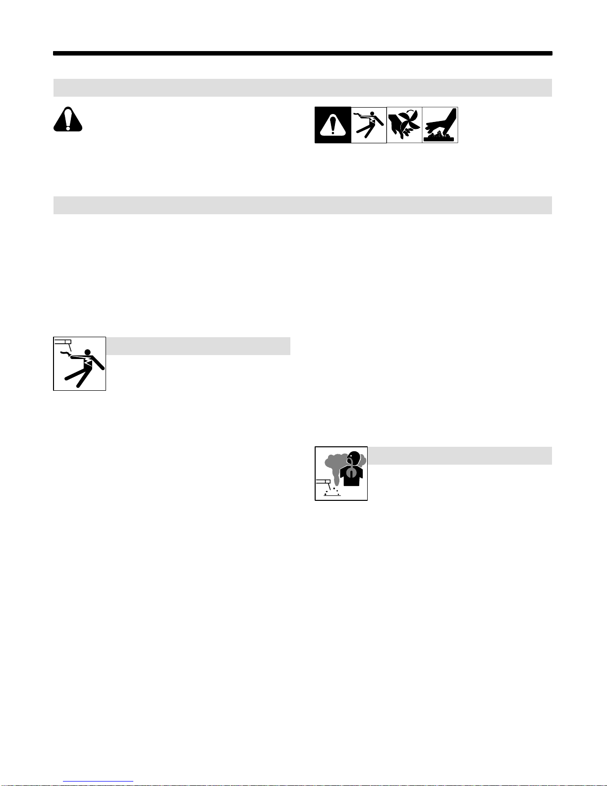
1-1. Signification des symboles
Signifie « Mise en garde. Faire preuve de vigilance. »
Cette procédure présente des risques identifiés par les
symboles adjacents aux directives.
YIdentifie un message de sécurité particulier.
.Signifie « NOTA » ; n’est pas relatif à la sécurité.
Ce groupe de symboles signifie « Mise en garde. Faire preuve de vigi-
lance. » Il y a des dangers liés aux CHOCS ÉLECTRIQUES, aux
PIÈCES EN MOUVEMENT et aux PIÈCES CHAUDES. Se reporter
aux symboles et aux directives ci-dessous afin de connaître les me-
sures à prendre pour éviter tout danger.
1-2. Dangers relatifs au soudage à l’arc
YLes symboles ci-après sont utilisés tout au long du présent
manuel pour attirer l’attention sur les dangers potentiels et les
identifier. Lorsqu’on voit un symbole, faire preuve de vigilance et
suivre les directives mentionnées afin d’éviter tout danger. Les
consignes de sécurité énoncées ci-après ne font que résumer le
contenu des normes de sécurité mentionnées à la section 1–4.
Lire et respecter toutes ces normes.
YL’installation, l’utilisation, l’entretien et les réparations ne doi-
vent être confiés qu’à des personnes qualifiées.
YPendant l’utilisation de l’appareil, tenir à l’écart toute personne,
en particulier les enfants.
LES DÉCHARGES ÉLECTRIQUES
peuvent être mortelles.
Un simple contact avec des pièces sous tension peut
causer une électrocution ou des blessures graves.
L’électrode et le circuit de soudage sont sous tension
dès que l’appareil est en fonctionnement. Le circuit
d’entréeet les circuits internes de l’appareil sont également sous tension.
En soudage semi–automatique ou automatique, le fil, le dévidoir, le
logement des galets d’entraînement et les pièces métalliques en contact
avec le fil de soudage sont sous tension. Tout matériel mal installé ou mal
mis à la terre présente un danger.
DNe jamais toucher aux pièces électriques sous tension.
DPorter des gants et des vêtements de protection secs et exempts de
trous.
DS’isoler de la pièce et de la terre au moyen de tapis ou autres disposi-
tifs isolants suffisamment grands pour empêcher tout contact
physique avec la pièce ou la terre.
DNe pas se servir d’une source de courant alternatif dans les zones humi-
des, les endroits confinés ou là où on risque de tomber.
DNe se servir d’une source de courant alternatif QUE si le procédé de souda-
ge l’exige.
DSi l’utilisation d’une source de courant alternatif s’avère nécessaire, se ser-
vir de la fonction de télécommande si l’appareil en est équipé.
DCouperl’alimentation ou arrêter le moteur avant de procéder à l’instal-
lation, à la réparation ou à l’entretien de l’appareil. Couper/étiqueter
l’alimentation selon la norme OSHA 29 CFR 1910.147 (voir les nor-
mes de sécurité).
DInstaller et mettre à la terre correctement l’appareil conformément à
son manuel d’utilisation et aux codes nationaux, provinciaux et
municipaux.
DToujours vérifier la terre du cordon d’alimentation – Vérifier et s’assu-
rer que le fil de terre du cordon d’alimentation est bien raccordé à la
bornede terre du sectionneur ou que la fiche du cordon est raccordée
à une prise correctement mise à la terre.
DPour exécuter les branchements d’entrée, fixer d’abord le conducteur
de mise à la terre adéquat et contre–vérifier les connexions.
DVérifier fréquemment le cordon d’alimentation et s’assurer qu’il n’est
ni endommagé ni dénudé ; le remplacer immédiatement s’il est en-
dommagé – tout câble dénudé peut causer une électrocution.
DMettre l’appareil hors tension quand on ne l’utilise pas.
DNe pas utiliser de câbles usés, endommagés, de calibre insuffisant ou
mal épissés.
DNe pas s’enrouler les câbles autour du corps.
DSi la pièce soudée doit être mise à la terre, le faire directement avec un
câble distinct.
DNe pas toucher l’électrode quand on est en contact avec la pièce, la
terre ou une électrode d’une autre machine.
DN’utiliser que du matériel en bon état. Réparer ou remplacer sur–le–
champ les pièces endommagées. Entretenir l’appareil conformément
au présent manuel.
DPorter un harnais de sécurité quand on travaille en hauteur.
DMaintenir solidement en place tous les panneaux et capots.
DFixer le câble de retour de façon à obtenir un bon contact métal sur
métal avec la pièce à souder ou la table de travail, le plus près possible
de la soudure.
DNe pas connecter plus d’une électrode ou plus d’un câble de masse à un
même terminal de sortie.
Il subsiste un COURANT CONTINU IMPORTANT
dans les convertisseurs après la suppression de
l’alimentation électrique.
DArrêter les convertisseurs, débrancher le courant électrique et dé-
charger les condensateurs d’alimentation selon les instructions
énoncées à la section Entretien avant de toucher les pièces.
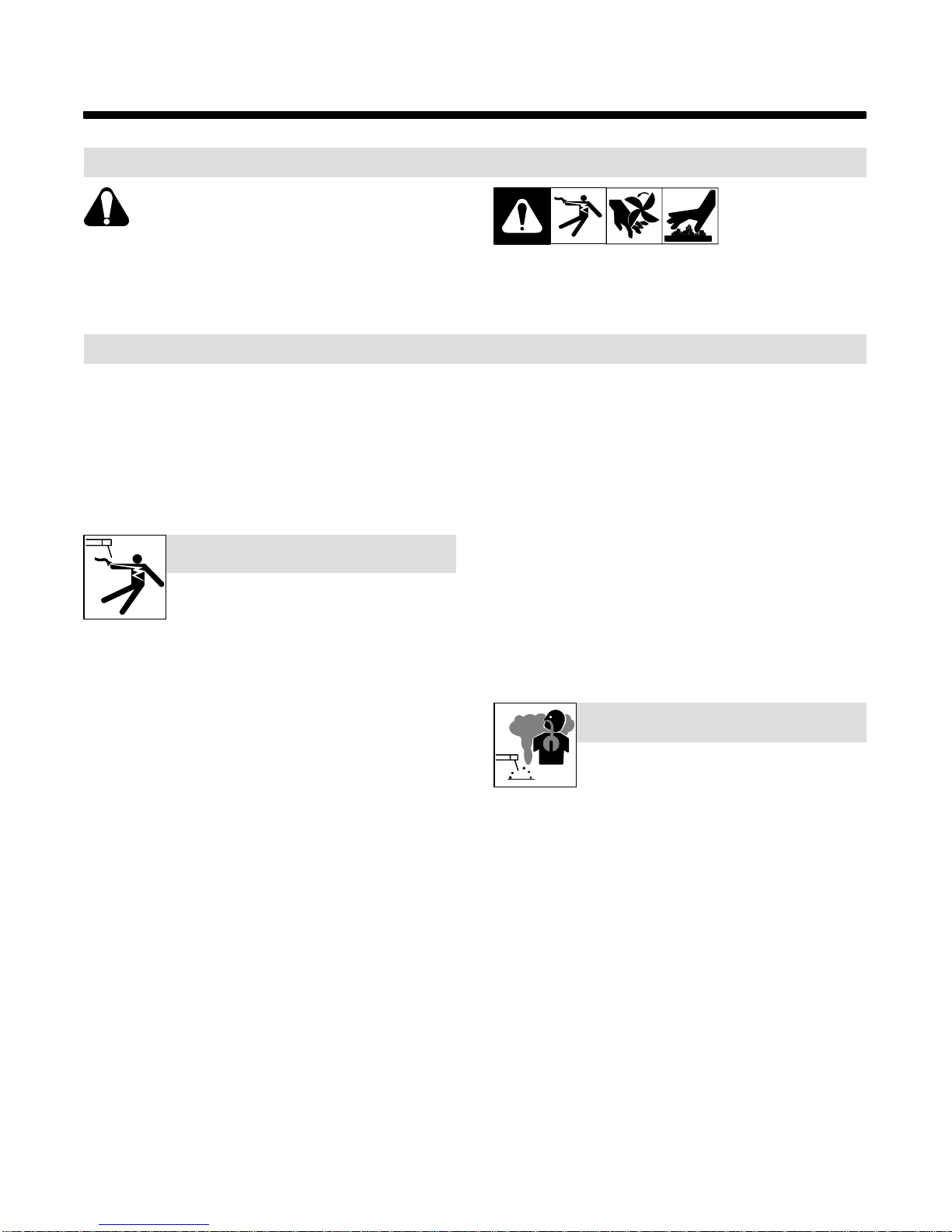
Le soudage génère des fumées et des gaz dont
l’inhalation peut être dangereuse pour la santé.
LES FUMÉES ET LES GAZ peuvent
être dangereux.
DSe tenir à distance des fumées et ne pas les inhaler.
DÀ l’intérieur, ventiler la zone et/ou utiliser un dispositif d’aspiration au
niveau de l’arc pour l’évacuation des fumées et des gaz de soudage.
DSi la ventilation est insuffisante, utiliser un respirateur à adduction
d’air agréé.
DLire les fiches techniques de santé–sécurité (FTSS) et les instruc-
tions du fabricant concernant les métaux, les consommables, les
revêtements, les nettoyants et les dégraisseurs.
DNe travailler dans un espace clos que s’il est bien ventilé ouporter un
respirateurà adduction d’air. Demander toujours à un surveillant dû-
ment formé de se tenir à proximité. Des fumées et des gaz de soudage
peuvent se substituer à l’air, abaisser la teneur en oxygène et causer
des lésions ou des accidents mortels. S’assurer que l’air est respira-
ble.
DNe pas souder à proximité d’opérations de dégraissage, de nettoyage
ou de pulvérisation. La chaleur et les rayons de l’arc peuvent réagir en
présence de vapeurs et former des gaz hautement toxiques et irri-
tants.
DNe pas souder de métaux munis d’un revêtement, tels que la tôle
d’acier galvanisée, plombée ou cadmiée, à moins que le revêtement
n’ait été enlevé dans la zone de soudage, que l’endroit soit bien venti-
lé, et si nécessaire, porter un respirateur à adduction d’air. Les
revêtements et tous les métaux renfermant ces éléments peuvent dé-
gager des fumées toxiques lorsqu’on les soude.