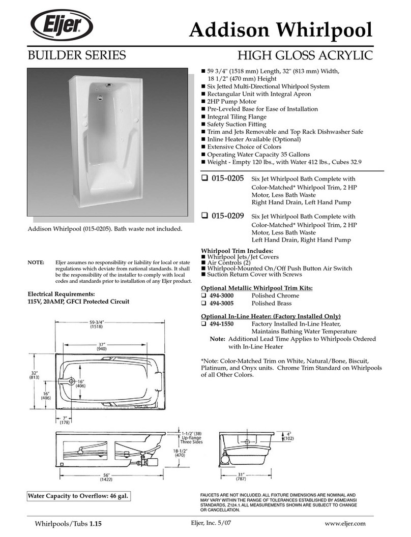
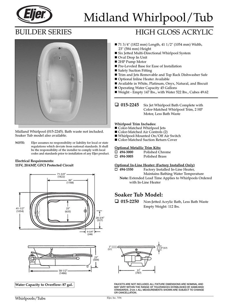
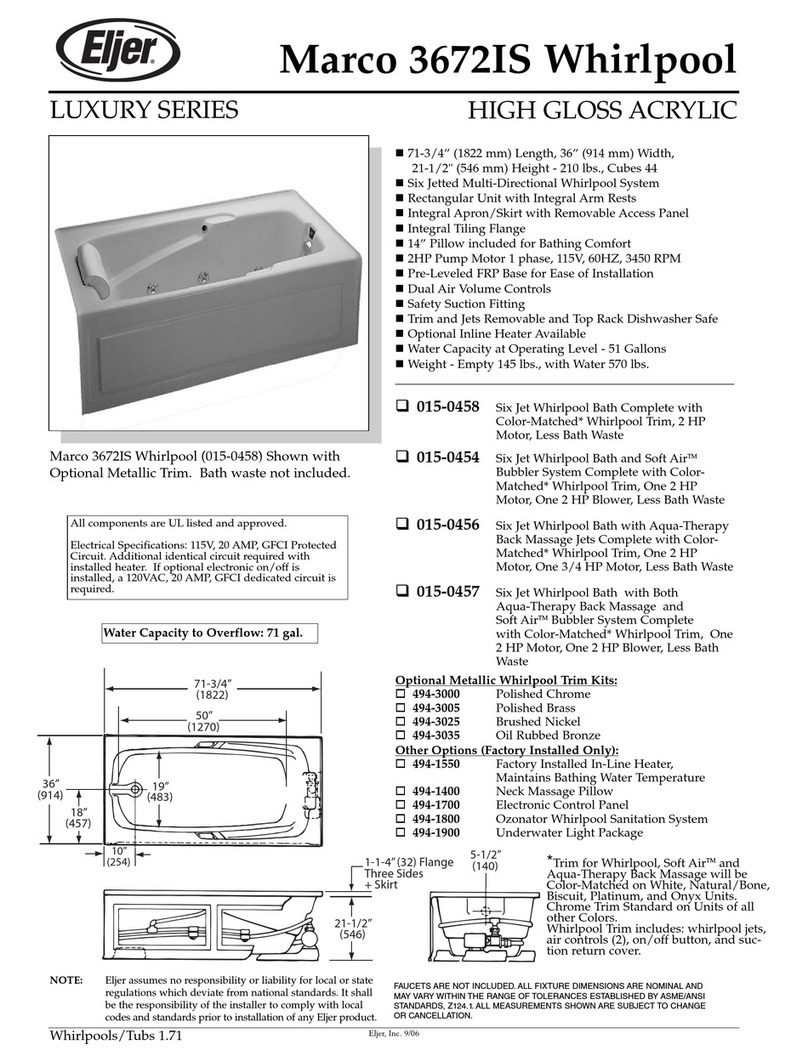
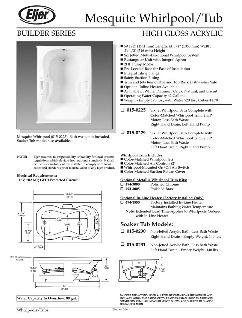
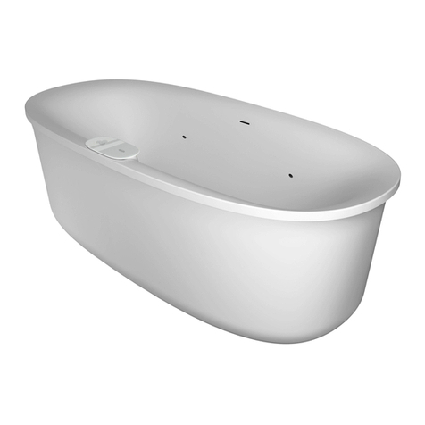
Eljer 015-0005 User manual

754764-100
1
THANK YOU...
for selecting an Eljer bathing product. Your new bath is shipped to you after careful inspection. The whirlpool
version is completely assembled with pump and circulatory system piping. All you need to finish the installation
are your selected fittings, electrical connections and support bedding material.
To ensure maximum performance and pleasure from this product, please follow the instructions and cautions.
© Eljer 2011
All product names listed herein are trademarks of Eljer unless otherwise noted.
For questions or service issues, please call Technical Support 1-(800)-442-1902.
Please do not contact or return product to the store.
MODEL NUMBERS
015-0005, 015-0015, 015-0026,
015-0066, 015-0076, 015-0077,
015-0305, 015-0309
PREMIERE WHIRLPOOL
INSTALLATION AND
OPERATION MANUAL

2
754764-100
TABLE OF CONTENTS:
Cover
................................................................................................Page 1
Table of Contents
..............................................................................Page 2
Safety Instructions Notice.................................................................Page 3
Installation, Framing and Post Installation
Clean-Up Instructions.......................................................................Page 4
Typical Flange & Under Deck Mounting Instructions........................Page 6
General Specifications for Whirlpools................................................Page 7
Roughing-in References for All Model Series...................................Pages 8 - 10
Electrical Installation Instructions
.....................................................Page 11
Total Massage Whirlpools.............
....................................................Page 12
Operating Instructions.......................................................................Page 13
Cleaning and Maintenance...............................................................Page 14
Warranty
......................................
.....................................................Page 15

754764-100
3
!
!
!
!
!
!
!
WARNING: Risk of personal injury. Do not permit children to use this unit without adult supervision.
WARNING: Risk of personal injury. Do not operate this unit without the guard over the suction fitting.
WARNING: Risk of electric shock. Do not permit electrical appliances (hair dryer, telephone, radio, etc.) within
60 inches (1524mm) of this unit.
WARNING: Risk of hyperthermia and possible drowning. People using medications and/or having adverse
medical history should consult a physician before using this product.
WARNING: Risk of personal injury. Do not overfill unit before entering. Entering tub when filled more than 2/3
can cause overflow and slippery conditions. Exercise caution when entering and exiting.
WARNING: No Food or Alcoholic Beverages. Use of your bathtub immediately after meals is not
recommended. Avoid alcohol consumption before or during bathing. Alcoholic beverages can cause drowsiness or
hyperthermia resulting in loss of consciousness or even drowning.
WARNING: Pregnancy. If you are or think you may be pregnant, consult your physician before using the bathtub.
Never drop or insert any object into any opening.
Use this unit only for its intended use as described in this manual. Do not use any attachments not recommended by
American Standard.
The unit must be connected only to a supply circuit that is properly protected by a ground-fault circuit-interrupter
(GFCI). Such a GFCI should be provided by the installer and should be tested on a routine basis. To test the GFCI,
push the test button. The GFCI should interrupt power. Push the reset button. Power should be restored. If the GFCI
fails to operate in this manner, the GFCI is defective. If the GFCI interrupts power to the bathtub without the test button
being pushed, a ground current is flowing, indicating the possibility of an electric shock. Do not use this hydromassage
bathtub. Disconnect the hydromassage bathtub and have the problem corrected by a licensed electrician before using.
A pressure wire connector is provided on the exterior of the motor unit to permit connection of a no. 8 AWG solid
copper bonding conductor between this unit and all other electrical equipment and exposed metal in the vicinity, as
needed to comply with local requirements. To reduce the risk of an electric shock, connect this connector to the
grounding terminal of your electric service or supply panel with a conductor equivalent in size to the circuit conductors
supplying this unit.
IMPORTANT
SAFETY
INSTRUCTIONS
INSTRUCTIONS PERTAINING TO
A RISK OF FIRE, ELECTRIC SHOCK
OR INJURY TO PERSONS
READ AND FOLLOW ALL INSTRUCTIONS!

4
754764-100
Each bath arrives ready for installation, completely equipped with the pump and plumbing
necessary for operation. However, a drain/overflow kit is required for each bath and it is
not included.
The variety of installations for this bath may require framing procedures other than those shown.
Locate studs as required. Ensure roughing-in dimensions are proper, plumb, and square.
Installation and Framing Instructions
Remove the bath from the carton. Retain the shipping carton until satisfactory
inspection of the product has been made. Do not lift the bath by the plumbing at
any time; handle by the shell only.
All bath units are factory tested for proper operation and watertight connections
prior to shipping. Prior to installation and before enclosing with wallboard, tile,
etc., the bath must be filled with water and operated to check for leaks that may
have resulted from shipping damage or mishandling.
The sumps of these baths are not supported by the feet and additional sump
support is required. Mortar (not cement) is recommended as support material.
Once the bath is in place, the rim of the bath should contact the stringer or pier
but supports no weight.
Provisions must be made in all installations for an access opening for servicing the
bath pump. Unless an access opening of at least 12" x 24" (305mm x 610mm) is
provided, warranty service will not be performed. It is strongly recommended that an
additional opening be provided for access to drain components.
Each bath has a nominal length (L), width (W), and Height (H) along with a rim
height. Unless otherwise noted in the following rough-in references, assume
that the nominal tolerances are as much as +/-1/4 inch (6mm). Therefore, it is
strongly recommended that the installer build the surrounding structure after
receiving the actual bath. Structural measurements should be verified against
the actual bath received to ensure proper fit.
!
!
!
!
!
POST INSTALLATION CLEAN-UP
Remove all construction debris from bath. Tile grout can be removed with a wooden
popsicle stick or tongue depressor.
Do not use wire brushes or any other metal implement on bath surface.
Post installation clean-up generally can be completed using warm water and liquid
dishwashing detergent.
Stubborn dirt or stains may be removed using granular Spic and Span®mixed with water.
Painter's naphtha can be used to remove excess adhesives and/or wet oil-base paint.

754764-100
5
INSTALLATION AND FRAMING INSTRUCTIONS
The variety of installations possible for this whirlpool may require framing procedures other than those shown. Locate studs as
needed. Ensure roughing-in dimensions are proper, plumb and square. Provisions must be made in all installations for an access
opening for servicing the pump and controls. It is strongly recommended that an additional opening be provided for access to the
drain components. The apron should not be used as the primary access opening.
TYPICAL PIER TYPE INSTALLATION
AS DESIRED
F
CUTOUT
AS DESIRED
G
CUTOUT
C
24
(610 mm)
12
(305 mm)
MOUNTING
SURFACE
WATERPROOF
SEALANT
BATH
TYPICAL RECESS INSTALLATION
24
(610 mm)
12
(305 mm)
C
E
D
W
LEVELING
STRINGERS
TILE
TILE
BEAD
STRIP
LEVELING STRINGER
1 x 4 (not for support)
BATH
ADHESIVE
SEALANT
WALLBOARD
NOTE: Tile bead kit not included and
must be purchased separately.
C*
TYPICAL INSTALLATION
FIGURE 1
The bath must be supported along its entire bottom. Use mortar as
bedding material (do not use sand or foam). Apply enough mortar to support
the complete bottom of the bath. After the mortar has been poured, and before
it sets, position whirlpool or bath within recess until the rim is leveled against
the leveling stringers (see "Typical Recess Installation") shown below.
The rim of the bath must not support weight. Allow the mortar material to
completely harden before applying weight to the rim or bottom of the bath. Any
finish material such as tile or wall board must be self-supporting if it contacts
the deck of the bath.
3. Install drain components to the whirlpool following the drain installation instructions.
Before replacing your whirlpool for final installation, be certain that an opening has
been provided in the sub-floor for the drain. See the roughing-in drawing and
Table 1 for suggested opening size (shadowed) and location dimensions. The
drain/overflow of the bath extends below the bottom of the bath. Note that this
requires a cutout in the floor.
The floor structure beneath the bath must be able to support a total weight of bath,
water, and bather. Refer to Table 1 under total weight for your model.
2. Remove the whirlpool and attach a 1 x 4 stringer to the studs, with the top of the stringer touching the traced line.
The rim of the bath must not support weight.
1. Position the whirlpool into the installation opening and level the deck in both directions, shimming the integral leveling feet IF
necessary. Mark the final position of the underside of the deck by tracing a line on to the studs (see Figure 1).
!
!
!
ACCESS PANEL MUST BE LOCATED
ON THE SAME SIDE AS THE MOTOR.
ALLOW OPEN FRAMING ON PUMP/MOTOR
END FOR SERVICE.
ACCESS PANEL MUST BE LOCATED
ON THE SAME SIDE AS THE MOTOR.
ALLOW OPEN FRAMING ON
PUMP/MOTOR END FOR SERVICE.
FOR E & D DIMENSIONS SEE TABLE 1 ON PAGE 7. FOR C, G & F DIMENSIONS SEE TABLE 1 ON PAGE 7.
NOTE:
FRONT EDGE
OF BATH MUST
BE SUPPORTED
BY STUD WALL OR
ELJER APRON KIT
UNLESS AN ACCESS OPENING OF AT LEAST 12" X 24" (305 X 610mm)
IS PROVIDED,WARRANTY SERVICE WILL NOT BE PERFORMED.
UNLESS AN ACCESS OPENING OF AT LEAST 12" X 24" (305 X 610mm)
IS PROVIDED,WARRANTY SERVICE WILL NOT BE PERFORMED.
ACCESS PANELS NOT REQUIRED
FOR BATH TUBS. ACCESS PANELS NOT REQUIRED
FOR BATH TUBS.
SEE TABLE 1 ON PAGE 7.
This manual suits for next models
7
Table of contents
Other Eljer Hot Tub manuals
Popular Hot Tub manuals by other brands
CalderaSpas
CalderaSpas CalderaSpas Utopia Series owner's manual

anko
anko SS-601A user manual

CalderaSpas
CalderaSpas CANTABRIA owner's manual

Dimension One Spas
Dimension One Spas HYDRO SPORT Installation and owner's guide
Bestway
Bestway Lay-Z-Spa Maldives HydroJet Pro manual
Dimension One Spas
Dimension One Spas Nautilus Specifications
