Elk Products ELK-M1XSP User manual

ELK-M1XSP
Lighting Interface, Thermostat Interface,
and Serial Port Expander
INSTALLATION
MANUAL
M1XSP Rev. G 5/2/2011 Printed in USA
PO Box 100
3266 US Hwy 70 West
Hildebran, NC 28637
828-397-4200 828-397-4415 Fax
http://www.elkproducts.com
IMPORTANT NOTICE: Every effort has been made to assure the accuracy of the information contained in this docu-
ment as of the date printed.
The extent of integration between Elk Products and other Partner Mfgs varies from product to product. Some integra-
tion is more powerful or feature rich than others. In some cases there are variables or limitations not within Elk's
control which may render certain desirable features unavailable or unusable. Certain Partner Mfgs products and/or
protocols, including Elk's may not contain the capabilities or data definitions to permit additional integration beyond
what is currently available. In addition, Partner Mfgs may, at their option, add, modify, or discontinued features or
support with little or no notification.
Drawings, illustrations, diagrams, part numbers, etc. contained and shown in this document are provided as refer-
ence only. All information is based on equipment available from or provided by the Partner Mfg. at the time the
information was created. A Partner Mfg may in fact offer similar or alternative equipment in their line that Elk has not
evaluated, and therefore Elk cannot guarantee operational compatibility.
For reasons stated herein, Elk Products makes no warranty that it will be able to integrate all available features or
operations, nor does it make any express or implied warranties of fitness for a particular purpose or of merchantability.
Refer to Elk's Limited Warranty.
Specifications are Subject to Change without notice.

M1XSP Installation Manual
Page 2
APPLICATION:
The ELK-M1XSP is a "3 in 1" product. As a lighting interface, it adapts the M1 Control to many brands of Lighting control products
which use “serial" communications. As a thermostat interface, it adapts the M1 Control to HVAC Serial Communicating
Thermostats. As a serial port expander, it expands the RS-232 communication ports of the M1 to allow serial communications
with many types and brands of equipment which communicate using serial ASCII commands. i.e., Personal Computers, etc.
Jumpers on the M1XSP select the appropriate application, connection, and protocol. Most importanly, the M1XSP operates
from the 4-wire (RS-485) M1 Keypad data bus, allowing RS-232 ports to be located long distances from the control. The M1G
and M1EZ8 Controls will support up to 7 M1XSPs. The communications baud rate is adjustable from 300 to 38,400 baud. The
unit comes complete with cable and a black surface mountable housing.
FEATURES:
•Adapts the M1 and M1EZ8 to specific Lighting control products which use "serial" communications.
•Adapts the M1 and M1EZ8 to specific HVAC Communicating Thermostats from RCS, Aprilaire, and HAI
•Expands the M1 and M1EZ8 RS-232 Serial Ports
•Connect to and Operates from the RS485 Data Bus
•Address Settings via DIP Switches
•Jumper Options and LED Diagnostic indicator
•On-Board EOL Bus Termination Jumper
•Flash Memory for Firmware Updating
SPECIFICATIONS:
•Maximum of Expandable Ports (Units): 7 with M1G or M1EZ8
•Operating Voltage: 12 Volts D.C.
•Current Draw: 31mA
•Housing Dimensions: 4.375" x 3.0" x 1.125"
•Circuit Board Dimensions: 3.5" x 2.75
Table of Contents
General Installation and Setup ..................................................................................................... 3
Updating/Replacing Firmware in the ELK-M1XSP....................................................................................4
Aprilaire 8870 Thermostat ............................................................................................................. 5
RCS TR16 (RS-232 Format) Thermostat ...................................................................................... 6
RCS TR16/TR40 (RS-485 Format) Thermostats .......................................................................... 7
HAI OmniStat 1 (RC) & OmniStat 2 Series (RS-232) Themostats .............................................. 8
Carrier Infinity HVAC System 'Themostat' ................................................................................. 10
Lighting Controllers with RS-232 "Serial" Interfaces ............................................................... 11
OnQ-ALC - (Individual Lighting Switches) .................................................................................. 12
UPB - (Individual Lighting Loads and Links) .............................................................................. 14
Centralite (Individual Lighting Loads and Scenes) ................................................................... 16
Lutron RadioRA - (Phantoms, Zones, Security Flash/Solid, Master Ctrl Buttons) ........................ 18
INSTEON - (Individual Lighting Loads and Scenes) ................................................................... 20
LEVITON ViziaRf (ZWave) Lighting .......................................................................................... 24
UPLINK 2500 and AnyNET Cellular Radios............................................................................... 25
W800RF32 X-10 RF Receiver ...................................................................................................... 26
AES Intellinet Radio Subscriber Unit ......................................................................................... 27
Data Bus E.O.L. Termination - VERY IMPORTANT! .............................................................................. 29
M1XSP Compatibility, Jumper Settings and Misc. Information ................................................ 32
NOTICE: Some product interfaces require the M1XSP to contain a specific firmware version by "flash" updating in
the field. Updates can be downloaded from the ELK Products Website http://www.elkproducts.com. See list of
Firmware versions on page 4.

M1XSP Installation Manual Page 3
General Installation and Setup
1. The M1XSP operates on the M1's Keypad data bus and may be remotely located near the equipment to which it is
interfacing. Two (2) #6 x 1/2" screws (not provided), one on each side of the black box should be used. It can also be
mounted inside the M1 cabinet using the same method OR by removing the board from the black box and installing the
board into a pair of ELK-SWG Plastic Glide brackets.
2. Before making any wiring connections, turn Off the M1 Master Power Switch.
3. Connect terminals +12V, A, B, and Neg from the M1XSP to the M1's Keypad Data Bus (terminals +VKP, Data A, Data B, &
Neg). NOTE: Refer to the M1 Installation Manual and the M1DBH information in this manual about proper
connections of data bus devices with multiple homerun cables.
4. There are 4 address switches, each with a position of OFF or ON (binary value 0 or 1) and a decimal equivalent value of
(1, 2, 4, or 8). The total decimal value of the "ON" switches equates to the data bus address. As a rule, the first M1XSP
should be set to address 1. If more than 1 M1XSP is installed, set each one to a unique (sequential) address (2, 3, etc).
IMPORTANT: Only data bus addresses 1, 2, 3, or 4 are valid when interfacing with HAI Thermostats. Data bus address 1 MUST
be selected for HAI Thermostats numbered 1 thru 4. Data bus address 2 for HAI Thermostats numbered 5 to 8. Data bus
address 3 for HAI Thermostats numbered 9 to 12. Data bus address 4 for HAI Thermostats numbered 13 to 16.
5. Set the "Mode" and "Baud" jumpers according to the desired application. Refer to the jumper settings table on the back of
this manual for a complete listing of these jumpers. In some cases the baud rate is not required as it is internally fixed
according to the mode/protocol.
"DB9" 9 Pin
RS-232
Connection to
other Mfg.
INSTALL UNIT * SET ADDRESS AND OPTION JUMPERS * ACTIVATE M1 BUS ENROLLMENT PROCESS
RS-485
M1 Data Bus
Connection
RS-485
Connection
to other Mfg.
Data Bus
Address
Switches
Jumpers
S1,S2,S3 select
BAUD rate
Jumpers
S4,S5,S6,S7,S8
select Interface
MODE
J1 -Factory
Use ONLY!
JP3 - Jumper selects
between RS-232 or
RS-485
JP5 - Jumper Selects
+12VDC to DB9 Pin 4
(MUST be in-place for
HAI Thermostats)
JP1 - Jumper selects
termination of M1
RS-485 Data Bus
JP2 - Jumper selects
termination of
other Mfg. RS-485
Table 1: Data Bus Address Switch Settings
ON
1 2 3 4
ON
1 2 3 4
ON
1 2 3 4
ON
1 2 3 4
Address 1
ON
1 2 3 4
ON
1 2 3 4
ON
1 2 3 4
Address 2 Address 3 Address 4
Address 5 Address 6 Address 7
LEGEND
ON
OFF
M1XSP Data Bus Terminating Jumper
JP1 Used to engage a 120 Ohm resistor for
terminating the M1 RS-485 Data Bus. See
Data bus wiring instructions before use.
For an M1XSP the only valid Data Bus
Addresses are 1 thru 7 since the max.
number of M1XSPs is 7.

M1XSP Installation Manual
Page 4
Steps 6 & 7 may be skipped when using the M1XSP as a Lighting or Themostat interface.
6. If the M1XSP is being used as a general purpose serial port expander then you will definetly need to set the BAUD Rate
Jumpers to the desired speed. Refer to the jumper settings table on the back of this manual.
7. As a serial port expander, the M1XSP can be connected to a PC or other communication equipment using a standard 9
pin RS-232 serial cable. Distance for an RS-232 serial cable is 10 ft. nominal, 50 ft. maximum. Since the M1XSP
operates on the M1's 4-wire Keypad Data Bus, it can be located a great distance from the M1 and thereby closer to the
other equipment so that the RS-232 length limits are not such an issue.
8. Set the RS232 or RS485 communications format jumper (JP3) according to the equipment being interfaced. In most
cases this jumper will be set to the "232" position. Refer to the jumper settings table on the back of this manual.
9. Refer to the equipment wiring diagrams on the following pages.
10. After all connections are complete, turn On the M1 Master Power Switch.
11. Enroll the M1XSP into the M1 Control. From the Keypad access the Installer level programming and select Menu 01-Bus
Module Enrollment. Press the right arrow key to start the enrollment. Onceenrollment has completed, press the right
arrow key to view results. Enrolled M1XSPs will show up as type 5 (T5) followed by the specific address number.
NOTE: To replace an defective M1XSP, set the new unit to the same address as the old unit and repeat the enrollment
process. If a device needs to be permanently removed, perform the enrollment process after removing the device,
M1XSP Diagnostic LED indicator
Slow blink (1/2 sec.) = Normal communication with M1.
Fast flicker = Communicating with other equipment (Thermostat, Lighting Controller, PC, etc.)
No blink = No communication with M1. Unit might be unplugged or powered off.
otherwise a "missing" trouble condition will appear.
FIRMWARE VERSIONS:
The factory "default" firmware shipped with the M1XSP supports several partner products. However, some specific partner
products require a special version of Firmware to be flashed into the M1XSP. Please refer to the firmware versions below:
The 1st digit (1,25,50,etc) denotes the partner or volume identifier. The 2nd and 3rd digits are used for revision levels.
1.x.x Factory "Out-of-the-box" Firmware: Aprilaire,RCS,HAI,OnQ-ALC,UPB,Centralite,EDT,Dynalite,LutronRA,W800RF32, etc.
10.x.x Field Installable Firmware: Uplink "AnyNet" and AES Intellinet Radio.
20.x.x Field Installable Firmware: Vizia "RZCOP" ZWave interface. (Downloadable from Elk Website)
25.x.x Field Installable Firmware: Elk-M1XZW Z-Wave Module. (Used only in the M1XZW, a subset of the M1XSP)
30.x.x Field Installable Firmware: Centralite "JetStream" only. (Downloadable from Elk M1 Website)
40.x.x Field Installable Firmware: Carrier "Infinity" HVAC only. (Downloadable from Elk M1 Website)
50.x.x Field Installable Firmware: INSTEON "Lighting" only.
60.x.x Field Installable Firmware: Advantage Air HVAC only. {Australia} (Downloadable from Elk M1 Website)
70.x.x Field Installable Firmware: HAI OmniStat and OmniStat 2 Thermostats (Downloadable from Elk M1 Website)
Updating/Replacing Firmware in the ELK-M1XSP
The M1XSP stores it’s operating firmware in “Flash” memory. This state-of-the-art memory allows electronic field updates
and eliminates the old fashion method of changing IC chips or shipping boards back to the factory. As new firmware updates
become available, they will be posted on ELK’s Dealer ONLY restricted website found at www.elkproducts.com. NOTE:
Firmware updating can only be done through the M1 Control using a Direct to PC Com port connection or an optional
Ethernet Network connection. Dial-up connections cannot be used to perform firmware updates.
How to Update Firmware:
1. Physically connect the Computer and Control using either the RS-232 Serial Port 0 or the M1XEP Ethernet Interface.
3. Start ElkRP and open the account belonging to the control. Click on the Connection menu icon and establish a connec-
tion. Again, use the appropriate Direct using Com_ OR Network options.
4. On the Send/Rcv menu icon there is a selection that allows the firmware to be updated.
5. Select the device to be updated. In this case it is a Serial Expander. Select the update firmware option.
6. Display will show: Device name, current Firmware, Hardware, and Bootware version, and a pull down window for selecting
the update firmware. NOTE: All update (.bin) files downloaded or received should be stored in a directory on your com-
puter. Refer to the Options tab under the Setup menu in RP. It will indicate what directory is used for the update files.
7. Click on the check box for “Update”. If “Reprogram” or “Rollback” is displayed the firmware file is the same as OR older
that what is in the control. Reprogramming with the same firmware is a waste of time but was included for factory testing
purposes. Rollback is not recommended except under the guidance of Elk Technical Support.

M1XSP Installation Manual Page 5
POWER
Aprilaire
Electronic Thermostat
Model 8811 Protocol Adapter
Power
7.5VAC RS-485 RS-485 RS-232
C
LEDs
RX TX
DATA
RS-485
RX TX
ENABLE
RS-485
RX TX
DATA
RS-232
BA
RS-485
Not Used
BL/WT
The thermostat brand, interface format, and model of ELK-M1
Control dictates the total number of thermostats allowed.
The ELK-M1G can interface with up to 16 Aprilaire 8870
Thermostats total using 1 M1XSP.
The ELK-M1 (Std) can only interface with 2 Aprilaire 8870 Thermostats.
+VKP A B Neg
To M1 Control
Data Bus Terminals
ADDRESS
Switch 1 shown in ON
position (Address 1).
Switches 2,4,8 are Off.
MODE
For Aprilaire
set to 1011 **
Place plug on top
pins for a 1, on
bottom for a 0.
BAUD
No changes
needed.
OR/WT
BK/WT
RD/WT
Aprilaire 8818
DISTRIBUTION
PANEL
One required per
eight (8) thermostats
Aprilaire 8870
THERMOSTATS
HVAC
SYSTEM
HVAC
SYSTEM
Address
1248
ELK-M1XSP
Interface
1
0
1 2 3 4
RS-232
ON
232 485
JP1
JP2
JP3
+12V A B Neg JP5
Jumper JP3
must be in 232
position.
6 ft. Cable with RJ and DB9 connector
shipped with Aprilaire 8811.
BAUD MODE
1
0S1 S2 S3
S5 S6 S7 S8
** Early production units do not have the S5 Jumper
S5 S6 S7 S8
1. Install and wire the Aprilaire 8811 Protocol Adapter, 8818 Distribution Panel (optional), and the 8870 Thermostat using
instructions from Aprilaire.
2. Install the ELK-M1XSP per the instructions on page 3. Be sure to enroll the device into the M1.
3. Set the MODE jumpers S5=1, S6=0, S7=1, & S8=1for Aprilaire. If the M1XSP has a jumper S4, set it to =1. Set Jumper
JP3 to the "232" position. The BAUD jumpers S1,S2, & S3 do not matter as the Aprilaire baud rate is preset internally.
4. Plug the Aprilaire supplied 6 ft RJ to DB9 Cable between the 8811 Protocol Adapter and the ELK-M1XSP. DO NOT USE
THE ELK-WO37A CABLE.
5. Power up the Aprilaire Thermostat and Protocol Adapter.
6. Program the unit address and any other options in the Thermostat per its instructions. The unit address must match the
Thermostat number in the M1 Control. The first Thermostat should be Address 1.
7. Using the ELK-RP Software, program the M1 using steps A,B, and C. Test and verify operation using steps D and E.
7a. Click on the Automation Tab in the ELK-RP software. Click on Thermostat icon and program a name for Thermostat 1.
7b. Click on the Task icon and program at least two tasks. Name the 1st Task "Economy Mode" and the 2nd "Comfort Mode".
7c. Click on the Rules icon and create the following 4 rules.
Whenever [Area Name] Armed State Becomes Armed Away Whenever [Task Name] (Task 1) Is Activated
Then Activate [Economy Mode] (Task 1) Then Set [Thermostat 1] (TStat 1) Cooling Desired Temp to 85 degrees
Whenever [Area] Armed State Becomes Disarmed Whenever [Task Name] (Task 2) Is Activated
Then Activate [Comfort Mode] (Task 2) Then Set [Thermostat 1] (TStat 1) Cooling Desired Temp to 70 degrees
7d. Use the M1 Keypad to verify the M1XSP & Thermostat operation. Press the ELK key followed by the Right arrow key to
access Menu 1-View/Control Automation Fncts. Press 6 for the Thermostat Temperature sub-menu, followed by Right
arrow key. The Keypad should display the first Thermostat (T01) along with its name and current temperature reading.
7e. Go into the Tasks sub-menu and select Economy Mode (Task 1). Press the # key to activate. When this task is activated
the thermostat cooling setpoint should go to 85 degrees. Confirm this on the display.
Aprilaire 8870 Thermostat

M1XSP Installation Manual
Page 6
RS-485
Not Used
To M1 Control
Data Bus Terminals
Thermostat brand, interface format, and model of ELK-M1 Control dictates the total number of thermostats allowed.
The M1G supports 7 RCS-TR16 (RS-232 models). However, each thermostat requires a dedicated M1XSP.
NOTE: The ELK-M1G can support up to 16 of the RCS-TR16/TR40 (RS-485 models) using a single (1) M1XSP.
* The ELK-M1 (Std) can only support 2 RCS thermostats.
+VKP A B Neg
ADDRESS
Switch 1 shown in ON
position (Address 1).
Switches 2,4,8 are Off.
MODE
For RCS
set to 1001 **
BAUD
No changes
needed.
Place plug on top
pins for a 1, on
bottom for a 0.
Address
1248
ELK-M1XSP
Interface
1
0
1 2 3 4
RS-232
ON
232 485
JP1
JP2
JP3
+12V A B Neg JP5
Jumper JP3
must be in 232
position.
Part # WO37A - 10 ft. Cable with 4 flying leads
and DB9 connector
BAUD MODE
1
0S1 S2 S3
S5 S6 S7 S8
** Early production units do not have the S5 Jumper
S5 S6 S7 S8
RCS TR16
"RS-232"
Control Unit
RS-232
GND
+12VDC
CLOCK
DATA
HVAC SYSTEM
12V
GND
D +
D -
WDU
TS16
Wall Display
Unit
GND
+12VDC
CLOCK
DATA
GREEN
RED
BLACK
WHT (YEL)
Connection of White (Yel) wire is optional. It can
be used to supply +12VDC from the M1XSP to the
thermostat control unit in lieu of the HVAC power.
If not used, tape or insulate the White (Yel) wire.
1. Install, and wire the RCS Control Unit and Wall Display Unit to the HVAC system per the RCS instructions.
2. Install the ELK-M1XSP per the instructions on page 3. Be sure to enroll the device into the M1.
3. Set the MODE jumpers S5=1, S6=0, S7=0, & S8=1for RCS mode. If the M1XSP has jumper S4, set it to =1. Set Jumper
JP3 to the "232" position. The BAUD jumpers S1,S2, & S3 do not matter as the RCS baud rate is preset internally.
4. Connect the Black, Red, and Green wires from the ELK-WO37A cable to the RS-232 terminals on the RCS Thermostat
Control unit. The White (Yellow) wire is optional. It may be used to supply +12VDC from the M1XSP to the Thermostat in
lieu of the HVAC power. Consult the RCS manual for details. Plug the other end of the ELK-WO37A cable into the 9 pin
serial connector on the M1XSP.
5. Power up the RCS Thermostat Control Unit.
6. Program the Unit Address and any other options in the RCS Unit per its instructions. The unit address must match the
Thermostat number in the M1 Control. The first Thermostat should be Address 1.
7. Using the ELK-RP Software, program the M1 using the following steps. Test and verify operation using steps d and e.
7a. Click on the Automation Tab in the ELK-RP software. Click on Thermostat icon and program a name for Thermostat 1.
7b. Click on the Task icon and program at least two tasks. Name the 1st Task "Economy Mode" and the 2nd "Comfort Mode".
7c. Click on the Rules icon and create the following 4 rules.
Whenever [Area Name] Armed State Becomes Armed Away Whenever [Task Name] (Task 1) Is Activated
Then Activate [Economy Mode] (Task 1) Then Set [Thermostat 1] (TStat 1) Cooling Desired Temp to 85 degrees
Whenever [Area] Armed State Becomes Disarmed Whenever [Task Name] (Task 2) Is Activated
Then Activate [Comfort Mode] (Task 2) Then Set [Thermostat 1] (TStat 1) Cooling Desired Temp to 70 degrees
7d. Use the M1 Keypad to verify the M1XSP & Thermostat operation. Press the ELK key followed by the Right arrow key to
access Menu 1-View/Control Automation Fncts. Press 6 for the Thermostat Temperature sub-menu, followed by Right
arrow key. The Keypad should display the first Thermostat (T01) along with its name and current temperature reading.
7e. Go into the Tasks sub-menu and select Economy Mode (Task 1). Press the # key to activate. When this task is activated
the thermostat cooling setpoint should go to 85 degrees. Confirm this on the Thermostat display.
RCS TR16 (RS-232 Format) Thermostat
The RCS TR16 (RS-232 Format) is rare and is replaced by the TR16/TR40 (RS485 Format) models.
Part # ELK-W046A - DB9 Serial Cable for M1XSP

M1XSP Installation Manual Page 7
RCS TR16/TR40
"RS-485"
Control Unit
RS-485
RS-232
Not Used
To M1 Data Bus
Connections
GND
+VKP A B Neg
+12VDC
CLOCK
DATA
HVAC SYSTEM
ADDRESS
Switch 1 shown in ON
position (Address 1).
Switches 2,4,8 are Off.
MODE
For RCS
set to 1001 **
BAUD
No changes
needed.
Place plug on top
pins for a 1, on
bottom for a 0.
Address
1248
ELK-M1XSP
Interface
BAUD MODE
1
0
RS-232
ON
232 485
JP1
JP2
JP3
+12V A B Neg JP5
Jumper JP3
must be in 485
position.
22 awg. - 3 conductors (Max. length 1500 ft.)
WHITE
BLACK
GREEN
To additional Thermostats
Control Units
RS-485
1
0S1 S2 S3
S5 S6 S7 S8
** Early production units do not have the S5 Jumper
S5 S6 S7 S8
1 2 3 4
12V
GND
D +
D -
WDU
TS?
Wall Display
Unit
GND
+12VDC
CLOCK
DATA
WHITE
GREEN
BLACK
RED
RCS TR16/TR40
"RS-485"
Control Unit
Wall
Display Unit
WHITE
GREEN
RED
BLACK RCS TR16/TR40
"RS-485"
Control Unit
Wall
Display Unit
WHITE
RED
BLACK
GREEN
TSTAT #1
TSTAT #2 TSTAT #3
12V
GND
D +
D -
12V
GND
D +
D -
HVAC SYSTEM
HVAC SYSTEM
RCS TR16/TR40 Thermostat
(RS-485 format)
Thermostat brand, interface format, and model of ELK-M1 Control dictates the total number of thermostats allowed.
The M1G supports up to 16 of the RCS-TR16/TR40 (RS-485 models) using a single (1) M1XSP.
* The ELK-M1 (Std) can only support 2 RCS thermostats.
1. Install, and wire the RCS Control Unit and Wall Display Unit to the HVAC system per the RCS instructions.
2. Install the ELK-M1XSP per the instructions on page 3. Be sure to enroll the device into the M1.
3. Set the MODE jumpers S5=1, S6=0, S7=0, & S8=1for RCS mode. If the M1XSP has jumper S4, set it to =1. Set Jumper
JP3 to the "485" position. The BAUD jumpers S1,S2, & S3 do not matter as the RCS baud rate is preset internally.
4. Using a 3 conductor cable and the diagram below, connect the GND, D+, and D- wires from the RS-485 terminals on the
RCS Thermostat Control unit to the RS-485 terminals on the M1XSP. The supplied WO37A cable (RS-232) is not used.
5. Power up the RCS Thermostat Control Unit.
6. Program the Unit Address and any other options in the RCS Unit per its instructions. The unit address must match the
Thermostat number in the M1 Control. The first Thermostat should be Address 1.
7. Using the ELK-RP Software, program the M1 using the following steps. Test and verify operation using steps d and e.
7a. Click on the Automation Tab in the ELK-RP software. Click on Thermostat icon and program a name for Thermostat 1.
7b. Click on the Task icon and program at least two tasks. Name the 1st Task "Economy Mode" and the 2nd "Comfort Mode".
7c. Click on the Rules icon and create the following 4 rules.
Whenever [Area Name] Armed State Becomes Armed Away Whenever [Task Name] (Task 1) Is Activated
Then Activate [Economy Mode] (Task 1) Then Set [Thermostat 1] (TStat 1) Cooling Desired Temp to 85 degrees
Whenever [Area] Armed State Becomes Disarmed Whenever [Task Name] (Task 2) Is Activated
Then Activate [Comfort Mode] (Task 2) Then Set [Thermostat 1] (TStat 1) Cooling Desired Temp to 70 degrees
7d. Use the M1 Keypad to verify the M1XSP & Thermostat operation. Press the ELK key followed by the Right arrow key to
access Menu 1-View/Control Automation Fncts. Press 6 for the Thermostat Temperature sub-menu, followed by Right
arrow key. The Keypad should display the first Thermostat (T01) along with its name and current temperature reading.
7e. Go into the Tasks sub-menu and select Economy Mode (Task 1). Press the # key to activate. When this task is activated
the thermostat cooling setpoint should go to 85 degrees. Confirm this on the thermostat display.
RCS TR16/TR40 (RS-485 Format) Thermostats

M1XSP Installation Manual
Page 8
1. Connect the HAI OmniStat to the HVAC system per the instructions that came with the thermostat. After re-applying power
to the HVAC and OmniStat enter the Installer Setup Mode (see the HAI manual) and program as follows:
For OmniStat series 1:
A. Set the "Thermostat Address" to a value from 1 to 16. The first unit should be address 1. If multiple thermostats are installed,
each should be set to a consecutive address, starting at 1.
B. Set the "Communications Mode" to 300 Baud.
C. Set the "Display Options" to one of the options designated as "non-programmable" (4 thru 7). This is to disable the
thermostat's internal setback time schedules so they do not override the M1 Automation commands from the M1XSP.
An alternate method is to disable specific schedules by setting their times values to "----" (1 step past the 11:45pm time set).
D. Set the "Cool Setpoint Limit" and "Heat Setpoint Limit" if desired. Effectively, the thermostat will ignore any setpoint
commands sent to it that are outside these limits.
For OmniStat series 2:
A. Set the "Thermostat Address" to a value from 1 to 16. The first unit should be address 1. If multiple thermostats are installed,
each should be set to a consecutive address, starting at 1.
B. Set the "Communications Mode" to 2400 Baud.
C. Set the "System Options" to the option appropriate to the type of heat/cool system being connected.
D. Set the "Program Options" to either "None" or "Occupancy". This disables the thermostat's internal setback time schedules so
they do not override the M1 Automation commands from the M1XSP.
E. Set the "Cool Setpoint Limit" and "Heat Setpoint Limit" if desired. Effectively, the thermostat will ignore any setpoint
commands sent to it that are outside these limits.
2. Install the ELK-M1XSP and set its data bus address from 1 to 4 using the 4-position dip switch. IMPORTANT: The data
bus address MUST be coordinated with the OmniStat address as follows:
The M1XSP data bus address MUST be 1 when connected to OmniStats addressed as 1, 2, 3, or 4.
The M1XSP data bus address MUST be 2 when connected to OmniStats addressed as 5, 6, 7, or 8.
The M1XSP data bus address MUST be 3 when connected to OmniStats addressed as 9, 10, 11, or 12.
The M1XSP data bus address MUST be 4 when connected to OmniStats addressed as 13, 14, 15, or 16.
* If M1XSPs are in use with other devices they will have to be changed to addresses other than 1 to 4.
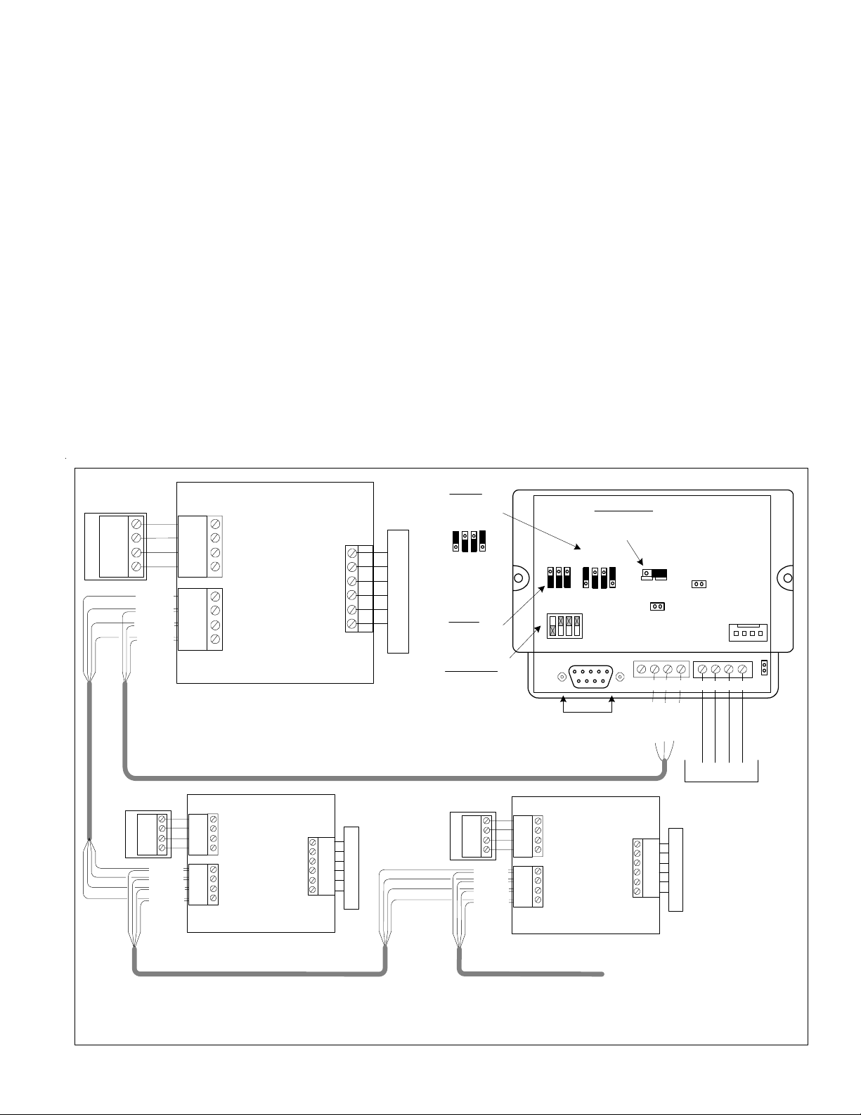
Perform a M1 data bus enrollment after setting the M1XSP data bus address switches. Up to four (4) OmniStats may be
connected to a single M1XSP. Using four (4) M1XSPs a total of sixteen (16) OmniStats may be connected.
3. For OmniStat 2 series the M1XSP must be firmware updated to version 70.0.2 (or the latest 70.x.x version).
4. Set the M1XSP MODE jumpers to: S5=1, S6=0, S7=1, & S8=0If the M1XSP has jumper S4, set it to =1.
5. Set the M1XSP BAUD jumpers as follows:
On Omnistat 1 series the baud rate must be set for 300 baud: S1=1, S2=0, S3=0
On Omnistat 2 series we recommend setting to 2400 baud: S1=1, S2=1 S3= [see note below]
* Omnistat 2 series may alternatively be set to 300, 1200, or 9600 baud. (refer to back page)
NOTE: Baud Jumper S3 has a special purpose with OmniStat 2 series. The normal setting is S3=0. However, if it is set to
S3=1 the M1XSP will pass along thermostat data in the form of ASCII data to the Elk-M1. This has been a requested feature
by some customers. Refer to the ElkM1 ASCII Protocol document for addition details.
6. On the M1XSP set Jumper JP3 to the "232" position. Make certain that Jumper JP5 is ON. THIS IS VERY IMPORTANT!
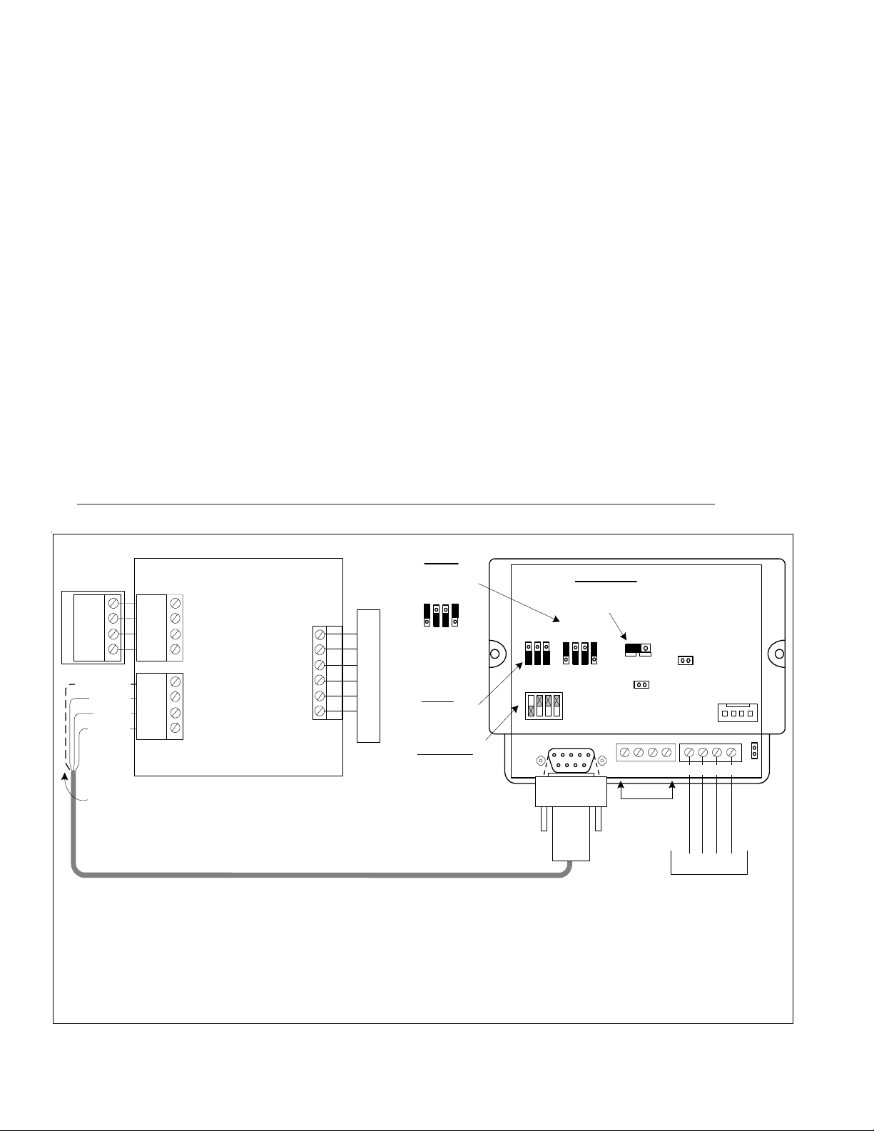
7. Splice the ELK-W037A serial cable (supplied) with a four conductor cable running to the OmniStat. Max. length is 500ft.
On OmniStat 1 series splice the four conductor cable to the Black, Red, Green, and Yellow four pin flying lead cable.
On OmniStat 2 series remove the factory jumper between terminals N/C and Black, then connect the four conductor cable
coming from the M1XSP according to the wiring diagram.
8. On OmniStat 2 series REMOVE Jumper J8 from the back side of the unit (if present). THIS IS VERY IMPORTANT!
9. Plug the ELK-WO37A cable into the 9 pin connector on the M1XSP.
10. Using the ELK-RP Software, program steps a, b, & c below. Then test and verify operation using steps d and e.
a. Select the Automation Tab in ELK-RP and pick the Thermostat icon. Program a name for each valid Thermostat.
b. Select the Task icon. Program two tasks: Name the 1st Task "Economy Mode" and the 2nd "Comfort Mode".
c. Select Rules icon and create the following 4 rules.
Whenever [Area Name] Armed State Becomes Armed Away Whenever [Economy Mode] (Task 1) Is Activated
Then Activate [Economy Mode] (Task 1) Then Set [Thermostat 1] (TStat 1) Cooling Desired Temp to 85 degrees
Whenever [Area] Armed State Becomes Disarmed Whenever [Comfort Mode] (Task 2) Is Activated
Then Activate [Comfort Mode] (Task 2) Then Set [Thermostat 1] (TStat 1) Cooling Desired Temp to 70 degrees
d. From the M1 Keypad PRESS the ELK key followed by the RIGHT arrow key to access Menu 1 - View/Control Automation
Fncts. Press 6 for the Thermostat Temperature sub-menu, followed by Right arrow key. The Keypad should now display
the Name and current temperature from Thermostat (T01).
e. Go back and select the Tasks sub-menu, then select Economy Mode (Task 1). Press the # key to activate. When this
task is activated the thermostat cooling setpoint should go to 85 degrees. Confirm this on the Thermostat display.
HAI OmniStat 1 (RC) & OmniStat 2 Series (RS-232) Themostats

M1XSP Installation Manual Page 9
RS-485
Not Used
To M1 Control Data
Bus Terminals
+VKP A B Neg
ADDRESS
Only Addresses 1, 2, 3, or 4
can be used with HAI Stats.
Address 1 shown (Switch 1 on).
MODE
HAI = 1010 **
1
0
BAUD
OmniStat 1 = 300 Baud
OmniStat 2 = 2400 Baud
Shorting plug on
top pins = 1,
bottom pins = 0.
Address
1248
ELK-M1XSP
Interface
1
0
1 2 3 4
RS-232
ON
232 485
JP1
JP2
JP3
+12V A B Neg JP5
Jumper JP3
must be in 232
position.
BAUD MODE
Four (4) pin "COMM" plug
(supplied with HAI OmniStat. )
HVAC SYSTEM
Hold
<
Prog
>
Mode Fan HAI
OMNISTAT
TSTAT #1
TSTAT #2 TSTAT #3 TSTAT #4
Shorting Plug
MUST be placed
on these two pins
for HAI Omnistats.
S1 S2 S3 S5 S6 S7 S8
S5 S6 S7 S8
** Older M1XSP units won't have the S5 and/or S4 Jumpers
BLK
RED
GRN
YEL
BLK
WHT
RED
YEL
BLK
GRN
RED
GRN
Up to 4 OmniStats
per M1XSP
Term. Block or Wire Splicers
Wiring Diagram for OmniStat 1 Series
Part # ELK-WO46A - DB9 4-conductor
serial cable for M1XSP
RS-485
Not Used
To M1 Control Data
Bus Terminals
+VKP A B Neg
ADDRESS
Only Addresses 1, 2, 3, or 4
can be used with HAI Stats.
Address 1 shown (Switch 1 on).
MODE
For HAI
set to 1010 **
1
0
Address
1248
ELK-M1XSP
Interface
1
0
1 2 3 4
RS-232
ON
232 485
JP1
JP2
JP3
+12V A B Neg JP5
Jumper JP3
must be in 232
position.
BAUD MODE
Part # ELK-WO46A - DB9 4-conductor
serial cable for M1XSP
TSTAT #1
TSTAT #2 TSTAT #3 TSTAT #4
Shorting Plug
MUST be placed
on these two pins
for HAI Omnistats.
S1 S2 S3 S5 S6 S7 S8
S5 S6 S7 S8
BLK
RED
GRN
YEL
BLK
WHT
RED
YEL
BLK
GRN
RED
GRN
Up to 4 OmniStats
per M1XSP
Term. Block or
Wire Splicers
OmniStat 2 OmniStat 2 OmniStat 2
Red
Yellow
Green
Black
N/C
Black
Green
Yellow
Red
Green
Black
Remote
Sensor
Comm
Remote
Temp
Remove jumper between N/C and Black terminals.
Black wire goes to N/C
Red wire goes to Black
Grn wire goes to Green
Yel wire goes to Yellow
*Pictured with
Thermostat
removed
(backplate only)
Wiring Diagram for OmniStat 2 Series
BAUD
OmniStat 1 = 300 Baud
OmniStat 2 = 2400 Baud
Shorting plug on
top pins = 1,
bottom pins = 0.
** Older M1XSP units won't have the S5 and/or S4 Jumpers
** IMPORTANT: Remove Jumper J8
ON back of Omnistat 2 (if present)

M1XSP Installation Manual
Page 10
Carrier Infinity HVAC System 'Themostat'
Interfacing to a Carrier Infinity HVAC System can be accomplished using the ELK-M1XSP connected to the Home
Automation Connection (RS-232) Port on the Infinity System Access Module "SAM" model # SYSTXCCSAM01. The
SAM supports two (2) Carrier Infinity HVAC systems. Each system can support eight (8) zones. The ELK-M1XSP can
communicate with up to 16 Thermostats. Refer to LIMITATIONS AND NOTES BELOW. The firmware in the M1XSP
MUST be manually updated to version 40.0.6 or greater. Firmware updates may be obtained from the Elk website.
Requirements:
1. ELK-M1G or ELK-M1EZ8 Control
2. ELK-M1XSP Serial Port Expander
3. Carrier Infinity System Access Module (SAM)
M1XSP Configuration:
1. Select an address from 1 to 7 using the 4-position dip switch, then enroll the M1XSP into the M1 system.
2. Update the M1XSP with firmware version 40.0.6 or later.
3. Remove jumper JP5.
4. Set Baud Rate Jumpers S1 = 1, S2 = 1, S3 = 1.
5. Set Mode Jumpers S5 = 1, S6 = 1, S7 = 1, S8 = 1
6. Select “232” for Jumper JP3.
7. Connect a standard 9 Pin serial cable between the M1XSP and the Carrier Infinity System Access Module (SAM).
Elk Thermostat 1 is assigned to Carrier System 1, Zone 1 Elk Thermostat 09 is assigned to Carrier System 2, Zone 1
Elk Thermostat 2 is assigned to Carrier System 1, Zone 2 Elk Thermostat 10 is assigned to Carrier System 2, Zone 2
Elk Thermostat 3 is assigned to Carrier System 1, Zone 3 Elk Thermostat 11 is assigned to Carrier System 2, Zone 3
Elk Thermostat 4 is assigned to Carrier System 1, Zone 4 Elk Thermostat 12 is assigned to Carrier System 2, Zone 4
Elk Thermostat 5 is assigned to Carrier System 1, Zone 5 Elk Thermostat 13 is assigned to Carrier System 2, Zone 5
Elk Thermostat 6 is assigned to Carrier System 1, Zone 6 Elk Thermostat 14 is assigned to Carrier System 2, Zone 6
Elk Thermostat 7 is assigned to Carrier System 1, Zone 7 Elk Thermostat 15 is assigned to Carrier System 2, Zone 7
Elk Thermostat 8 is assigned to Carrier System 1, Zone 8 Elk Thermostat 16 is assigned to Carrier System 2, Zone 8
LIMITATIONS & SPECIAL NOTES:
· The M1XSP and M1 supports the following Carrier system commands: Set Mode (Heat, Cool, Auto, Off, EHeat),
Set Fan (Auto, Med), Set Hold (Hold On, Hold Off), Set Current Heat Setpoint, Set Current Cool Setpoint, Set
Current Day, and Set Current Time
· The M1XSP and M1 DOES NOT support Low, High, or any variable speed Fan functions.
· The M1XSP and M1 DOES NOT support any Humidity functionality.
· The M1XSP and M1 DOES NOT support and Outside Temperature Probes.
It is Elk's understanding that different
models of SAM modules are available and
that each model retains the Home
Automation Connection (RS232) regardless
of the interface technology. However, it is
ultimately the responsibility of the Installer
to make sure the correct SAM module is
selected and that it includes the RS232
connection.

M1XSP Installation Manual Page 11
Lighting Controller Interface
or Circuit Board
RS-485
Not Used
To M1 Control
Data Bus Terminals
Consult the Lighting Manufacturer's Installation or Application Manual(s) for complete installation details.
+VKP A B Neg
ADDRESS SWITCHES
Switch 1 shown in ON
position (Address 1).
Switches 2,4,8 are Off.
MODE JUMPERS
Select according to the
table on Back Page.
1
0
BAUD JUMPERS
No changes needed. Address
1248
ELK-M1XSP
Interface
1
0
1 2 3 4
RS-232
ON
232
485
JP1
JP2
JP3
+12V A B Neg JP5
Jumper JP3
must be in 232
position.
BAUD MODE
Standard Computer type 9 Pin Serial Cable (Male/Female)
NOTE: Some manufacturers may supply a special cable.
RS-232
S1 S2 S3 S5 S6 S7 S8
S5 S6 S7 S8
1
0
Shorting plug on
top pins = 1,
bottom pins = 0.
** Older M1XSP units won't have the S5 and/or S4 Jumpers
Examples: OnQ-ALC, PCS-UPB, Centralite, Lutron, EDT-iLine, etc.
1. Install Lighting Controller using the instructions provided by the manufacturer. If the Lighting Controller's interface has an
address setting then set it to address 1. Most controllers do not require an address setting.
3. Install the ELK-M1XSP per the instructions on page 3.
4. Set Jumper JP3 to the "232" position.
5. Set the MODE jumpers to match the particular brand of lighting controller. See chart on page 10.
6. Set the BAUD rate jumpers to 000. (The M1XSP automatically sets the baud rate based on the MODE Jumper setting)
7. Connect a 9-pin serial cable from the Lighting Controller's serial port to the 9 pin connector on the M1XSP.
8. Apply power to the Lighting Controller and the M1XSP. DON'T FORGET TO ENROLL THE M1XSP INTO THE M1.
9. Program and test at least one light device using the ELK-RP Software and the following steps:
9a. Click on the Automation icon, then on the Lighting icon.
9b. Click on Lighting Device 1 and program the Name (1 to 16 characters), Format (manufacturer), and Type (switch,
dimmer, appliance). The "Show" box may be left blank or checked ("X"). If this box is checked, the light will be included in
the scroll list of the Keypad and Telephone remote View/Control Automation menus. If not selected for "Show" the light
will be available ONLY by manually entering the 3 digit number. Click on the Voice Description to program a 1 to 6 word
voice description for this light. Right click on Light 1 and select "Send Lighting 1" to send this programming to the M1.
9c. Click on the Rules icon and create the following 2 test rules.
Test Rule 1: WHENEVER 'Name' (Area 1) IS ARMED AWAY
THEN TURN 'Name' [1 [A1]] ON
Test Rule 2: WHENEVER 'Name' (Area 1) IS DISARMED
THEN TURN 'Name' [1 [A1]] OFF
9d. Click "Send" to transmit these rules to the M1.
9e. Test the manual activation of this light by pressing the ELK key on the M1 Keypad followed by the Right arrow key to select
"Menu 1-View/Control Automation Fncts. Press 2 for the Lighting submenu, followed by the Right arrow key. The keypad
will display the first Light name and number along with its On or Off status. Note: The status will not be correct if the M1 is
powered off. To change the light from On to Off or from Off to On, press the # key.
9f. Test the two automation rules by arming the control to the Away mode. The light should come On. Disarming the M1
should cause the light to turn Off.
10. This confirms the operation. Continue to add or test additional lights as required.
Lighting Controllers with RS-232 "Serial" Interfaces

M1XSP Installation Manual
Page 12
OnQ ALC is a low voltage "wired" lighting technology utilizing a central ALC Master Controller Interface communicating to light
switches and scene switches over a RS-485 proprietary network. An OnQ ALC Serial interface is required for interfacing the
Master Controller Interface with the ELK-M1XSP, and then into the M1 line of controls. The M1XSP supports 31 ALC modules
(dimmers, switches on each of 4 branches for a total of 124 individually addressable ALC devices. The M1XSP also supports
ALC 4 button scene switches, provided they are wired and connected on ALC branch 1.
Integration with the M1 is accomplished by "mapping" the ALC addresses and operation to M1 Lighting devices. For example:
ALC devices 1-31 on ALC branch 1 are mapped to M1 Lighting devices 1-31. Additional ALC devices may be added by the
additional of an ALC "branch" expander board in which case..... ALC devices 1-31 on ALC branch 2 are mapped to M1 Lighting
devices 33-63. ALC devices 1-31 on ALC branch 3 are mapped to M1 Lighting devices 65-95. ALC devices 1-31 on ALC branch
4 are mapped to M1 Lighting devices 97-127. M1 Lighting devices 32, 64, 96, and 128 are reserved for activation of the ALC
"Virtual Scenes" 1 thru 4 respectively. The chart on the next page shows the M1 Lighting devices and their corresponding ALC
device mapping.
Components required for OnQ ALC integration:
- An ELK-M1 or ELK-M1EZ8 Controller.
- One (1) ELK-M1XSP Serial Port Expander. NOTE: Firmware updates may be downloaded from the ELK M1 Dealer Web site.
- One (1) OnQ ALC Master Controller #364644-01and one (1) ALC Serial Interface #364698-01. ** See NOTE below.
- One or more ALC Lighting devices.
Limitations:
The M1XSP can only support ALC 4 button scene switches wired and connected on ALC branch 1.
Setting up the M1XSP and the M1 to communicate with OnQ ALC
1. Install the ELK-M1XSP per the instructions on page 3. Be sure to enroll the device into the M1.
2. Connect the RJ45 modular to 9-pin female serial cable supplied with the OnQ ALC Serial Interface to the male DB9 9 pin
serial connector (J2) on the ELK-M1XSP. The OnQ Lighting Controller is then connected to the OnQ Serial Interface. Note:
An optional expansion module OnQ part #364726-01 is required to obtain the full capacity of 124 Switches.
3. Set the MODE Jumpers on the M1XSP as follows: S4*="1" (UP), S5="1" (UP), S6="1" (UP), S7="0" (DN), S8="0" (DN).
NOTE: Some units do not have jumper S4.
4. Set the M1XSP Jumper JP3="232". The position of BAUD jumpers S1,S2,S3 does not matter.
5. Be sure to set the address switches on the ALC switches and use the OnQ Software to program the features.
6. Power up all the devices.
7. Program the M1 Lighting device attributes utilizing the ElkRP software. Only the specific devices to be used for ALC need to
be programmed. For each individual address program the M1 Lighting device as: "Format=Serial Expander" and "Type=
Dimmer" (Type may also be programmed as "On/Off Switch" if the device isn't dimmable).
When a M1 Light device is activated from a rule or from the M1 Keypad "Automation" menu, the corresponding device command
will be sent from the M1XSP to the ALC Serial Interface.
** NOTE: As of the release date of this manual OnQ had announced plans to produce a single module designated the "Elk
Interface". While not yet officially released the OnQ part number is believed to be 364864-01. This new part combines the
OnQ ALC Interface, the ALC Serial Interface, and the ELK-M1XSP, essentially replacing three components with a single
component. More information will be released once this product is available.
OnQ-ALC - (Individual Lighting Switches)

M1XSP Installation Manual Page 13
OnQ-ALC
Branch / Switch
B1 Switch 1
B1 Switch 2
B1 Switch 3
B1 Switch 4
B1 Switch 5
B1 Switch 6
B1 Switch 7
B1 Switch 8
B1 Switch 9
B1 Switch 10
B1 Switch 11
B1 Switch 12
B1 Switch 13
B1 Switch 14
B1 Switch 15
B1 Switch 16
B1 Switch 17
B1 Switch 18
B1 Switch 19
B1 Switch 20
B1 Switch 21
B1 Switch 22
B1 Switch 23
B1 Switch 24
B1 Switch 25
B1 Switch 26
B1 Switch 27
B1 Switch 28
B1 Switch 29
B1 Switch 30
B1 Switch 31
Virtual Scene 1
B2 Switch 1
B2 Switch 2
B2 Switch 3
B2 Switch 4
B2 Switch 5
B2 Switch 6
B2 Switch 7
B2 Switch 8
B2 Switch 9
B2 Switch 10
B2 Switch 11
B2 Switch 12
B2 Switch 13
B2 Switch 14
B2 Switch 15
B2 Switch 16
B2 Switch 17
B2 Switch 18
B2 Switch 19
B2 Switch 20
B2 Switch 21
B2 Switch 22
B2 Switch 23
B2 Switch 24
B2 Switch 25
B2 Switch 26
B2 Switch 27
B2 Switch 28
B2 Switch 29
B2 Switch 30
B2 Switch 31
Virtual Scene 2
ELK
Light
Device #
1
2
3
4
5
6
7
8
9
10
11
12
13
14
15
16
17
18
19
20
21
22
23
24
25
26
27
28
29
30
31
32
33
34
35
36
37
38
39
40
41
42
43
44
45
46
47
48
49
50
51
52
53
54
55
56
57
58
59
60
61
62
63
64
PLC
(X-10)
Ref.
A01
A02
A03
A04
A05
A06
A07
A08
A09
A10
A11
A12
A13
A14
A15
A16
B01
B02
B03
B04
B05
B06
B07
B08
B09
B10
B11
B12
B13
B14
B15
B16
C01
C02
C03
C04
C05
C06
C07
C08
C09
C10
C11
C12
C13
C14
C15
C16
D01
D02
D03
D04
D05
D06
D07
D08
D09
D10
D11
D12
D13
D14
D15
D16
OnQ-ALC
Branch / Switch
B3 Switch 1
B3 Switch 2
B3 Switch 3
B3 Switch 4
B3 Switch 5
B3 Switch 6
B3 Switch 7
B3 Switch 8
B3 Switch 9
B3 Switch 10
B3 Switch 11
B3 Switch 12
B3 Switch 13
B3 Switch 14
B3 Switch 15
B3 Switch 16
B3 Switch 17
B3 Switch 18
B3 Switch 19
B3 Switch 20
B3 Switch 21
B3 Switch 22
B3 Switch 23
B3 Switch 24
B3 Switch 25
B3 Switch 26
B3 Switch 27
B3 Switch 28
B3 Switch 29
B3 Switch 30
B3 Switch 31
Virtual Scene 3
B4 Switch 1
B4 Switch 2
B4 Switch 3
B4 Switch 4
B4 Switch 5
B4 Switch 6
B4 Switch 7
B4 Switch 8
B4 Switch 9
B4 Switch 10
B4 Switch 11
B4 Switch 12
B4 Switch 13
B4 Switch 14
B4 Switch 15
B4 Switch 16
B4 Switch 17
B4 Switch 18
B4 Switch 19
B4 Switch 20
B4 Switch 21
B4 Switch 22
B4 Switch 23
B4 Switch 24
B4 Switch 25
B4 Switch 26
B4 Switch 27
B4 Switch 28
B4 Switch 29
B4 Switch 30
B4 Switch 31
Virtual Scene 4
ELK
Light
Device #
65
66
67
68
69
70
71
72
73
74
75
76
77
78
79
80
81
82
83
84
85
86
87
88
89
90
91
92
93
94
95
96
97
98
99
100
101
102
103
104
105
106
107
108
109
110
111
112
113
114
115
116
117
118
119
120
121
122
123
124
125
126
127
128
PLC
(X-10)
Ref.
E01
E02
E03
E04
E05
E06
E07
E08
E09
E10
E11
E12
E13
E14
E15
E16
F01
F02
F03
F04
F05
F06
F07
F08
F09
F10
F11
F12
F13
F14
F15
F16
G01
G02
G03
G04
G05
G06
G07
G08
G09
G10
G11
G12
G13
G14
G15
G16
H01
H02
H03
H04
H05
H06
H07
H08
H09
H10
H11
H12
H13
H14
H15
H16
ELK
Light
Device #
129
130
131
132
133
134
135
136
137
138
139
140
141
142
143
144
145
146
147
148
149
150
151
152
153
154
155
156
157
158
159
160
161
162
163
164
165
166
167
168
169
170
171
172
173
174
175
176
177
178
179
180
181
182
183
184
185
186
187
188
189
190
191
192
PLC
(X-10)
Ref.
I01
I02
I03
I04
I05
I06
I07
I08
I09
I10
I11
I12
I13
I14
I15
I16
J01
J02
J03
J04
J05
J06
J07
J08
J09
J10
J11
J12
J13
J14
J15
J16
K01
K02
K03
K04
K05
K06
K07
K08
K09
K10
K11
K12
K13
K14
K15
K16
L01
L02
L03
L04
L05
L06
L07
L08
L09
L10
L11
L12
L13
L14
L15
L16
ELK
Light
Device #
193
194
195
196
197
198
199
200
201
202
203
204
205
206
207
208
209
210
211
212
213
214
215
216
217
218
219
220
221
222
223
224
225
226
227
228
229
230
231
232
233
234
235
236
237
238
239
240
241
242
243
244
245
246
247
248
249
250
251
252
253
254
255
256
PLC
(X-10)
Ref.
M01
M02
M03
M04
M05
M06
M07
M08
M09
M10
M11
M12
M13
M14
M15
M16
N01
N02
N03
N04
N05
N06
N07
N08
N09
N10
N11
N12
N13
N14
N15
N16
O01
O02
O03
O04
O05
O06
O07
O08
O09
O10
O11
O12
O13
O14
O15
016
P01
P02
P03
P04
P05
P06
P07
P08
P09
P10
P11
P12
P13
P14
P15
P16
The PLC column is for reference only.
OnQ-ALC
Branch/Node/SS
Scene Switch
B1/Node1/SS 2
B1/Node1/SS 3
B1/Node1/SS 4
B1/Node2/SS 2
B1/Node2/SS 3
B1/Node2/SS 4
B1/Node3/SS 2
B1/Node3/SS 3
B1/Node3/SS 4
B1/Node4/SS 2
B1/Node4/SS 3
B1/Node4/SS 4
B1/Node5/SS 2
B1/Node5/SS 3
B1/Node5/SS 4
B1/Node6/SS 2
B1/Node6/SS 3
B1/Node6/SS 4
B1/Node7/SS 2
B1/Node7/SS 3
B1/Node7/SS 4
B1/Node8/SS 2
B1/Node8/SS 3
B1/Node8/SS 4
B1/Node9/SS 2
B1/Node9/SS 3
B1/Node9/SS 4
B1/Node10/SS 2
B1/Node10/SS 3
B1/Node10/SS 4
B1/Node11/SS 2
B1/Node11/SS 3
B1/Node11/SS 4
B1/Node12/SS 2
B1/Node12/SS 3
B1/Node12/SS 4
B1/Node13/SS 2
B1/Node13/SS 3
B1/Node13/SS 4
B1/Node14/SS 2
B1/Node14/SS 3
B1/Node14/SS 4
B1/Node15/SS 2
B1/Node15/SS 3
B1/Node15/SS 4
B1/Node16/SS 2
B1/Node16/SS 3
B1/Node16/SS 4
B1/Node17/SS 2
B1/Node17/SS 3
B1/Node17/SS 4
B1/Node18/SS 2
B1/Node18/SS 3
B1/Node18/SS 4
B1/Node19/SS 2
B1/Node19/SS 3
B1/Node19/SS 4
B1/Node20/SS 2
B1/Node20/SS 3
B1/Node20/SS 4
B1/Node21/SS 2
B1/Node21/SS 3
B1/Node21/SS 4
B1/Node22/SS 2
OnQ-ALC
Branch/Node/SS
Scene Switch
B1/Node22/SS 3
B1/Node22/SS 4
B1/Node23/SS 2
B1/Node23/SS 3
B1/Node23/SS 4
B1/Node24/SS 2
B1/Node24/SS 3
B1/Node24/SS 4
B1/Node25/SS 2
B1/Node25/SS 3
B1/Node25/SS 4
B1/Node26/SS 2
B1/Node26/SS 3
B1/Node26/SS 4
B1/Node27/SS 2
B1/Node27/SS 3
B1/Node27/SS 4
B1/Node28/SS 2
B1/Node28/SS 3
B1/Node28/SS 4
B1/Node29/SS 2
B1/Node29/SS 3
B1/Node29/SS 4
B1/Node30/SS 2
B1/Node30/SS 3
B1/Node30/SS 4
B1/Node31/SS 2
B1/Node31/SS 3
B1/Node31/SS 4
M1 Lighting Devices Mapped to OnQ ALC
OnQ-ALC - (continued)

M1XSP Installation Manual
Page 14
UPB is a PLC or Powerline Communications lighting technology. There are 2 methods for interfacing UPB to M1. First is an
ELK-M1XSP connected to a UPB PIM 'S" (RS232 Serial Program Interface Module). Second is a new product called the
ELKM1PCSPIM (or PCSPIM 'E'). This product looks like an ordinary PIM but actually contains both a PIM and M1XSP processor
module. It connects directly to the M1 Data Bus and eliminates the RS232 cord/connection. NOTE: The M1PCSPIM is internally
fixed to M1 Bus Address #7, meaning that no other M1XSP's on the bus may be set to that address. Regardless of the type of
connection, M1 supports up to 192 UPB individual addresses (dimmers, switches) and 64 UPB Links (scenes).
Integration is accomplished by "mapping" the UPB addresses and operation to M1 Lighting device entities. UPB device
addresses 1-192 map to M1 Lighting devices 1-192. UPB Links 1-64 map to M1 Lighting devices 193-256. NOTE: Links
require M1XSP firmware version 1.0.14 or higher. The chart on the next page shows the M1 Light devices and UPB mappinig.
Components required for UPB integration:
- ELK-M1 or ELK-M1EZ8 Controller and the ElkRP Programming Software.
- ELK-M1XSP Serial Port Expander. Firmware updating may be required and may be downloaded from the ELK Web site.
- UPB PIM (Programming Interface Module) { or ELKM1PCSPIM which is internally fixed to M1 Bus Address #7}
- One or more UPB Lighting devices plus the UPB PC Programming Software called "UPStart."
Setting up to communicate with UPB { Skip steps 1 - 4 if you are using the new ELKM1PCSPIM }
1. Install the ELK-M1XSP per the instructions on page 3. Be sure to enroll the device into the M1.
2. Connect the female end of the supplied 9-pin serial cable to the M1XSP and the male end to the UPB PIM Module.
3. Set the MODE Jumpers on the M1XSP as follows: S4*="1" (UP), S5="1" (UP), S6="1" (UP), S7="0" (DN), S8="1" (UP).
NOTE: Some units do not have jumper S4.
4. Set the M1XSP Jumper JP3="232". Set JP5 to ON. The position of BAUD jumpers S1,S2,S3 does not matter.
5. Power up all the devices.
6. Using the ElkRP software, open the "Globals" folder. Then go to the "G29-G42 Special" tab and program the same unique
UPB NETWORK ID into the M1 that is stored in the UPB switches.
DO NOT USE NETWORK ID 0 OR 255 AS THESE ID HAVE SPECIAL PURPOSE RESERVED BY UPB.
7. In the ElkRP software open the Automation > Lighting folder and program the M1 Lighting devices. Only the devices
specifically for UPB use will need to be programmed. For UPB individual addresses program M1 Lighting devices: 1-192
as: Format=Serial Expander, Type= Dimmer (or "On/Off Switch" if the device isn't dimmable). For UPB link addresses
program M1 Lighting devices: 193-256 as: Format= Serial Expander, Type=On/Off Switch.
When an M1 Light device is activated from a rule or from the M1 Keypad "Automation" menu, the corresponding device com-
mand will be sent onto the powerline network to the UPB Devices.
Programming the UPB devices:
The UPB UPStart Software must be used to program each UPB module with an address, a network ID, and any other options.
IMPORTANT: The UPB NETWORK ID programmed into the UPB switches MUST MATCH the UPB NETWORK ID programming
into the ElkRP software. [ElkRP Globals folder > G29-G42 Special tab. DO NOT USE NETWORK ID 0 or Network ID 255.
UPB Device Status:
In order to receive "Load Status" changes from the UPB devices, make sure to program their option bit "Transmit Changes".
LIMITATIONS - CURRENT STATUS FROM UPB MODULES
Status reports resulting from manual rocker (pushbutton) changes. - UPB devices may be optionally programmed to
broadcast (report) their individual status whenever a manual change occurs via the rocker (pushbutton) switch. This
option requires UPStart PC Software and each device must be individually programmed. Go to tab labeled "Rocker
Switch". On this tab place a checkmark in the box option labeled "Report light level after rocker switch is pressed."
Status reports resulting from UPB LINK commands. - UPB devices DO NOT and CANNOT be programmed to broad-
cast (report) their status when changed by a LINK command. Because a LINK can affect anywhere from 1 to 255
devices simultaneously, the communications protocol does not permit status reports because the entire performance of
the UPB network could be adversly affected. For this reason, the status displayed by M1 Controller may not always
match the true status of UPB devices when devices are controlled by a Link command. This is a UPB protocol issue
and there is nothing (NO WORKAROUND) that Elk can do to resolve this issue.
PC based software packages with access to lots of memory are able to memorize which UPB switches belong to each
LINK along with their programmed (expected) response to each LINK. From this they are able to either anticipate the
expected status OR poll only each affected device in order to obtain their status report. But even this is not practical
when large numbers of devices are involved in a LINK. Simply put, it can take up to 5 minutes to poll all 255 potential
UPB devices, during which network traffic and device communications would be totally swamped and messages lost.
UPB - (Individual Lighting Loads and Links)

M1XSP Installation Manual Page 15
UPB
Switch 1
Switch 2
Switch 3
Switch 4
Switch 5
Switch 6
Switch 7
Switch 8
Switch 9
Switch 10
Switch 11
Switch 12
Switch 13
Switch 14
Switch 15
Switch 16
Switch 17
Switch 18
Switch 19
Switch 20
Switch 21
Switch 22
Switch 23
Switch 24
Switch 25
Switch 26
Switch 27
Switch 28
Switch 29
Switch 30
Switch 31
Switch 32
Switch 33
Switch 34
Switch 35
Switch 36
Switch 37
Switch 38
Switch 39
Switch 40
Switch 41
Switch 42
Switch 43
Switch 44
Switch 45
Switch 46
Switch 47
Switch 48
Switch 49
Switch 50
Switch 51
Switch 52
Switch 53
Switch 54
Switch 55
Switch 56
Switch 57
Switch 58
Switch 59
Switch 60
Switch 61
Switch 62
Switch 63
Switch 64
ELK
Light
Device #
1
2
3
4
5
6
7
8
9
10
11
12
13
14
15
16
17
18
19
20
21
22
23
24
25
26
27
28
29
30
31
32
33
34
35
36
37
38
39
40
41
42
43
44
45
46
47
48
49
50
51
52
53
54
55
56
57
58
59
60
61
62
63
64
PLC
(X-10)
Ref.
A01
A02
A03
A04
A05
A06
A07
A08
A09
A10
A11
A12
A13
A14
A15
A16
B01
B02
B03
B04
B05
B06
B07
B08
B09
B10
B11
B12
B13
B14
B15
B16
C01
C02
C03
C04
C05
C06
C07
C08
C09
C10
C11
C12
C13
C14
C15
C16
D01
D02
D03
D04
D05
D06
D07
D08
D09
D10
D11
D12
D13
D14
D15
D16
UPB
Switch 65
Switch 66
Switch 67
Switch 68
Switch 69
Switch 70
Switch 71
Switch 72
Switch 73
Switch 74
Switch 75
Switch 76
Switch 77
Switch 78
Switch 79
Switch 80
Switch 81
Switch 82
Switch 83
Switch 84
Switch 85
Switch 86
Switch 87
Switch 88
Switch 89
Switch 90
Switch 91
Switch 92
Switch 93
Switch 94
Switch 95
Switch 96
Switch 97
Switch 98
Switch 99
Switch 100
Switch 101
Switch 102
Switch 103
Switch 104
Switch 105
Switch 106
Switch 107
Switch 108
Switch 109
Switch 110
Switch 111
Switch 112
Switch 113
Switch 114
Switch 115
Switch 116
Switch 117
Switch 118
Switch 119
Load 120
Load 121
Load 122
Load 123
Load 124
Load 125
Load 126
Load 127
Load 128
ELK
Light
Device #
65
66
67
68
69
70
71
72
73
74
75
76
77
78
79
80
81
82
83
84
85
86
87
88
89
90
91
92
93
94
95
96
97
98
99
100
101
102
103
104
105
106
107
108
109
110
111
112
113
114
115
116
117
118
119
120
121
122
123
124
125
126
127
128
PLC
(X-10)
Ref.
E01
E02
E03
E04
E05
E06
E07
E08
E09
E10
E11
E12
E13
E14
E15
E16
F01
F02
F03
F04
F05
F06
F07
F08
F09
F10
F11
F12
F13
F14
F15
F16
G01
G02
G03
G04
G05
G06
G07
G08
G09
G10
G11
G12
G13
G14
G15
G16
H01
H02
H03
H04
H05
H06
H07
H08
H09
H10
H11
H12
H13
H14
H15
H16
ELK
Light
Device #
129
130
131
132
133
134
135
136
137
138
139
140
141
142
143
144
145
146
147
148
149
150
151
152
153
154
155
156
157
158
159
160
161
162
163
164
165
166
167
168
169
170
171
172
173
174
175
176
177
178
179
180
181
182
183
184
185
186
187
188
189
190
191
192
PLC
(X-10)
Ref.
I01
I02
I03
I04
I05
I06
I07
I08
I09
I10
I11
I12
I13
I14
I15
I16
J01
J02
J03
J04
J05
J06
J07
J08
J09
J10
J11
J12
J13
J14
J15
J16
K01
K02
K03
K04
K05
K06
K07
K08
K09
K10
K11
K12
K13
K14
K15
K16
L01
L02
L03
L04
L05
L06
L07
L08
L09
L10
L11
L12
L13
L14
L15
L16
ELK
Light
Device #
193
194
195
196
197
198
199
200
201
202
203
204
205
206
207
208
209
210
211
212
213
214
215
216
217
218
219
220
221
222
223
224
225
226
227
228
229
230
231
232
233
234
235
236
237
238
239
240
241
242
243
244
245
246
247
248
249
250
251
252
253
254
255
256
UPB
Switch 129
Switch 130
Switch 131
Switch 132
Switch 133
Switch 134
Switch 135
Switch 136
Switch 137
Switch 138
Switch 139
Switch 140
Switch 141
Switch 142
Switch 143
Switch 144
Switch 145
Switch 146
Switch 147
Switch 148
Switch 149
Switch 150
Switch 151
Switch 152
Switch 153
Switch 154
Switch 155
Switch 156
Switch 157
Switch 158
Switch 159
Switch 160
Switch 161
Switch 162
Switch 163
Switch 164
Switch 165
Switch 166
Switch 167
Switch 168
Switch 169
Switch 170
Switch 171
Switch 172
Switch 173
Switch 174
Switch 175
Switch 176
Switch 177
Switch 178
Switch 179
Switch 180
Switch 181
Switch 182
Switch 183
Switch 184
Switch 185
Switch 186
Switch 187
Switch 188
Switch 189
Switch 190
Switch 191
Switch 192
UPB
Link (Scene) 01
Link (Scene) 02
Link (Scene) 03
Link (Scene) 04
Link (Scene) 05
Link (Scene) 06
Link (Scene) 07
Link (Scene) 08
Link (Scene) 09
Link (Scene) 10
Link (Scene) 11
Link (Scene) 12
Link (Scene) 13
Link (Scene) 14
Link (Scene) 15
Link (Scene) 16
Link (Scene) 17
Link (Scene) 18
Link (Scene) 19
Link (Scene) 20
Link (Scene) 21
Link (Scene) 22
Link (Scene) 23
Link (Scene) 24
Link (Scene) 25
Link (Scene) 26
Link (Scene) 27
Link (Scene) 28
Link (Scene) 29
Link (Scene) 30
Link (Scene) 31
Link (Scene) 32
Link (Scene) 33
Link (Scene) 34
Link (Scene) 35
Link (Scene) 36
Link (Scene) 37
Link (Scene) 38
Link (Scene) 39
Link (Scene) 40
Link (Scene) 41
Link (Scene) 42
Link (Scene) 43
Link (Scene) 44
Link (Scene) 45
Link (Scene) 46
Link (Scene) 47
Link (Scene) 48
Link (Scene) 49
Link (Scene) 50
Link (Scene) 51
Link (Scene) 52
Link (Scene) 53
Link (Scene) 54
Link (Scene) 55
Link (Scene) 56
Link (Scene) 57
Link (Scene) 58
Link (Scene) 59
Link (Scene) 60
Link (Scene) 61
Link (Scene) 62
Link (Scene) 63
** Link (Scene) 64 Alarm Flash
PLC
(X-10)
Ref.
M01
M02
M03
M04
M05
M06
M07
M08
M09
M10
M11
M12
M13
M14
M15
M16
N01
N02
N03
N04
N05
N06
N07
N08
N09
N10
N11
N12
N13
N14
N15
N16
O01
O02
O03
O04
O05
O06
O07
O08
O09
O10
O11
O12
O13
O14
O15
016
P01
P02
P03
P04
P05
P06
P07
P08
P09
P10
P11
P12
P13
P14
P15
P16
The PLC column is for reference only.
M1 Lighting Devices Mapped to UPB
** Link (Scene) 64: When this link is activated from the M1, the M1 will automatically send a special "flash" command. All devices
are programmed to respond to Link 64 will immediately begin flashing until the link is de-activated (turned off) from the M1.
UPB - (continued)

M1XSP Installation Manual
Page 16
Elegance and LiteJet - Low voltage, centrally controlled lighting. All lights to be controlled are high voltage home run back to a dimmer/relay
enclosure. This enclosure contains an MCP Processor Board with an on-board RS232 serial port for interfacing with the M1XSP. Depending on
the particular Centralite model, the M1XSP can support up to 192 individual light devices (loads) and up to 64 lighting scenes.
Centralite StarLite and JetStream - Wireless lighting control. The M1XSP interfaces to a Centralite Master Interface or RS232 Bridge which
then wirelessly controls switches installed around the building. Depending on the model, up to 96 individual light devices (loads) and up to 64
lighting scenes can be controlled.
IMPORTANT: The M1XSP requires firmware version 30.x.x to support JetStream. This firmware is downloadable from the
Elk M1Dealer website. Select the M1XSP Firmware and look for the appropriate JetStream file. Starlite utilizes standard M1XSP
firmware (same as for LiteJet), however DIP switch #7 on the Starlite MCP must be set to ON so that Starlite will know to emulate
the LiteJet protocol.
Integration:
Integration with the M1 is accomplished by "mapping" the Centralite loads to M1 Lighting devices. For example: Centralite individual load 1 is
mapped to M1 Lighting devices 1. Scenes start at M1 Lighting device 193 and go up. E.G. Scene 1 is mapped as M1 Lighting device 193. The
chart shows the M1 Lighting devices and their corresponding Centralite Load/Scenes.
Components required:
- An ELK-M1 or ELK-M1EZ8 Controller.
- One (1) ELK-M1XSP Serial Port Expander. NOTE: Firmware updates may be downloaded from the ELK M1 Dealer Web site.
- Centralite LiteJet or Elegance with MCP processor board, JetStream with RS232 Bridge, or Starlite with MCP base unit.
- One or more Centralite lighting devices and/or switches.
Setting up the M1XSP and the M1 to communicate with Elegance, LiteJet, or Starlite
1. Install the ELK-M1XSP per the instructions on page 3. Be sure to enroll the device into the M1.
2. Connect the 9-pin serial cable between the M1XSP and serial connector on the Centralite MCP processor board marked "RS232-2".
3. Set M1XSP MODE Jumpers to: S4="1" (UP), S5="1" (UP), S6="1" (UP), S7="1" (UP), S8="0" (DN). NOTE: Some units do not have jumper
S4.
4. Set the M1XSP Jumper JP3="232". The position of BAUD jumpers S1,S2,S3 does not matter.
5. Power up all the devices.
6. Program the M1 Lighting device attributes utilizing the ElkRP software. Only the specific devices to be used for Centralite need to be
programmed. For individual addresses program M1 Lighting devices: 1-192 "Format=Serial Expander" and "Type= Dimmer" (Type
may also be programmed as "On/Off Switch" if the device isn't dimmable). For the scene addresses program M1 Lighting
devices: 193-256 as "Format= Serial Expander", "Type=On/Off Switch".
Load Status and/or Limitations with Elegance and LiteJet:
- The wallplate "button press" feature with LiteJet & Elegance is not directly usable with M1. However, by assigning a button to a load, even
a phantom (non-physical) load, it may be possible to use the status change of that load as a trigger with M1.
- To receive load status changes from Centralite the M1XSP MUST have firmware ver 1.0.14 or later and the Centralite Main Processor
MCP MUST have firmware ver 5.5 or later. There is a status Dipswich that must be set on the MCP. On the Elegance MCP Dipswitch
#5 must be set to ON. On the LiteJet MCP Dipswitch #6 must be set to ON. NOTE: DO NOT software program the load option to "send
changes". The Dipswitch settings will take care of this feature. Note: Version 5.5 or later of the Centralite firmware places a 1
second delay between each load change transmission. This means that multiple load changes can and will take several
seconds to reach the M1. An ALL ON command could take well over a minute for all loads to report in.
- Please note that under some conditions it may not be possible to obtain instantaneous real time lighting status updates.
Setting up the M1XSP and the M1 to communicate with JetStream
1. Install the ELK-M1XSP per the instructions on page 3. Be sure to enroll the device into the M1.
2. Download M1XSP firmware 30.x.8 (or later) from the Elk M1Dealer website and flash update the M1XSP. IMPORTANT!
3. Connect the 9-pin serial cable between the M1XSP and serial connector on the JetStream RS232 Bridge.
4. The M1XSP MODE Jumpers S1 to S8 are NOT APPLICABLE with this firmware and do not need to be changed or set.
5. Set the M1XSP Jumper JP3="232". The position of BAUD jumpers S1,S2,S3 does not matter.
6. If there is a shorting Jumper on JP5 remove it.
7. Power up all the devices.
6. Program the M1 Lighting device attributes utilizing the ElkRP software.
JetStream Configuration, Load Status and Limitations:
1. Install the JetStream devices into a "network" and program them using the JetStream USB programming dongle.
Follow the User's or Programming guide which came with the CentraLite JetStream system.
2. Add the RS-232 Bridge to the network. Refer to the section titled “Bringing the RS-232 Bridge into the Network” and “Configuring the
RS-232 Bridge for Your Area". Also the section “Third Party Control”. Verify that the baud rate for the RS232 bridge is set for 19200.
3. To get status updates the following steps MUST be performed:
a. Select the RS-232 Bridge in the Device List on the left hand side of the JetStream Software.
b. Check the box labeled “Update Third Party.”
4. Once step 4 has been completed there will be a new checkbox option available on each lighting device page. This option will be labeled
"Send T-Party". Check this box for any and all devices that status report is desired.
5. IMPORTANT! Click Send Device or Send All to make sure all devices are updated with the latest changes.
Centralite (Individual Lighting Loads and Scenes)

M1XSP Installation Manual Page 17
Centralite
Load 1
Load 2
Load 3
Load 4
Load 5
Load 6
Load 7
Load 8
Load 9
Load 10
Load 11
Load 12
Load 13
Load 14
Load 15
Load 16
Load 17
Load 18
Load 19
Load 20
Load 21
Load 22
Load 23
Load 24
Load 25
Load 26
Load 27
Load 28
Load 29
Load 30
Load 31
Load 32
Load 33
Load 34
Load 35
Load 36
Load 37
Load 38
Load 39
Load 40
Load 41
Load 42
Load 43
Load 44
Load 45
Load 46
Load 47
Load 48
Load 49
Load 50
Load 51
Load 52
Load 53
Load 54
Load 55
Load 56
Load 57
Load 58
Load 59
Load 60
Load 61
Load 62
Load 63
Load 64
ELK
Light
Device #
1
2
3
4
5
6
7
8
9
10
11
12
13
14
15
16
17
18
19
20
21
22
23
24
25
26
27
28
29
30
31
32
33
34
35
36
37
38
39
40
41
42
43
44
45
46
47
48
49
50
51
52
53
54
55
56
57
58
59
60
61
62
63
64
PLC
(X-10)
Ref.
A01
A02
A03
A04
A05
A06
A07
A08
A09
A10
A11
A12
A13
A14
A15
A16
B01
B02
B03
B04
B05
B06
B07
B08
B09
B10
B11
B12
B13
B14
B15
B16
C01
C02
C03
C04
C05
C06
C07
C08
C09
C10
C11
C12
C13
C14
C15
C16
D01
D02
D03
D04
D05
D06
D07
D08
D09
D10
D11
D12
D13
D14
D15
D16
Centralite
Load 65
Load 66
Load 67
Load 68
Load 69
Load 70
Load 71
Load 72
Load 73
Load 74
Load 75
Load 76
Load 77
Load 78
Load 79
Load 80
Load 81
Load 82
Load 83
Load 84
Load 85
Load 86
Load 87
Load 88
Load 89
Load 90
Load 91
Load 92
Load 93
Load 94
Load 95
Load 96
Load 97
Load 98
Load 99
Load 100
Load 101
Load 102
Load 103
Load 104
Load 105
Load 106
Load 107
Load 108
Load 109
Load 110
Load 111
Load 112
Load 113
Load 114
Load 115
Load 116
Load 117
Load 118
Load 119
Load 120
Load 121
Load 122
Load 123
Load 124
Load 125
Load 126
Load 127
Load 128
ELK
Light
Device #
65
66
67
68
69
70
71
72
73
74
75
76
77
78
79
80
81
82
83
84
85
86
87
88
89
90
91
92
93
94
95
96
97
98
99
100
101
102
103
104
105
106
107
108
109
110
111
112
113
114
115
116
117
118
119
120
121
122
123
124
125
126
127
128
PLC
(X-10)
Ref.
E01
E02
E03
E04
E05
E06
E07
E08
E09
E10
E11
E12
E13
E14
E15
E16
F01
F02
F03
F04
F05
F06
F07
F08
F09
F10
F11
F12
F13
F14
F15
F16
G01
G02
G03
G04
G05
G06
G07
G08
G09
G10
G11
G12
G13
G14
G15
G16
H01
H02
H03
H04
H05
H06
H07
H08
H09
H10
H11
H12
H13
H14
H15
H16
ELK
Light
Device #
129
130
131
132
133
134
135
136
137
138
139
140
141
142
143
144
145
146
147
148
149
150
151
152
153
154
155
156
157
158
159
160
161
162
163
164
165
166
167
168
169
170
171
172
173
174
175
176
177
178
179
180
181
182
183
184
185
186
187
188
189
190
191
192
PLC
(X-10)
Ref.
I01
I02
I03
I04
I05
I06
I07
I08
I09
I10
I11
I12
I13
I14
I15
I16
J01
J02
J03
J04
J05
J06
J07
J08
J09
J10
J11
J12
J13
J14
J15
J16
K01
K02
K03
K04
K05
K06
K07
K08
K09
K10
K11
K12
K13
K14
K15
K16
L01
L02
L03
L04
L05
L06
L07
L08
L09
L10
L11
L12
L13
L14
L15
L16
ELK
Light
Device #
193
194
195
196
197
198
199
200
201
202
203
204
205
206
207
208
209
210
211
212
213
214
215
216
217
218
219
220
221
222
223
224
225
226
227
228
229
230
231
232
233
234
235
236
237
238
239
240
241
242
243
244
245
246
247
248
249
250
251
252
253
254
255
256
Centralite
Load 129
Load 130
Load 131
Load 132
Load 133
Load 134
Load 135
Load 136
Load 137
Load 138
Load 139
Load 140
Load 141
Load 142
Load 143
Load 144
Load 145
Load 146
Load 147
Load 148
Load 149
Load 150
Load 151
Load 152
Load 153
Load 154
Load 155
Load 156
Load 157
Load 158
Load 159
Load 160
Load 161
Load 162
Load 163
Load 164
Load 165
Load 166
Load 167
Load 168
Load 169
Load 170
Load 171
Load 172
Load 173
Load 174
Load 175
Load 176
Load 177
Load 178
Load 179
Load 180
Load 181
Load 182
Load 183
Load 184
Load 185
Load 186
Load 187
Load 188
Load 189
Load 190
Load 191
Load 192
Centralite
Scene 01 All On
Scene 02 All Off
Scene 03 Vacation
Scene 04 Alarm Flash
Scene 05 Pwr-up Override
Scene 06
Scene 07
Scene 08
Scene 09
Scene 10
Scene 11
Scene 12
Scene 13
Scene 14
Scene 15
Scene 16
Scene 17
Scene 18
Scene 19
Scene 20
Scene 21
Scene 22
Scene 23
Scene 24
Scene 25
Scene 26
Scene 27
Scene 28
Scene 29
Scene 30
Scene 31
Scene 32
Scene 33
Scene 34
Scene 35
Scene 36
Scene 37
Scene 38
Scene 39
Scene 40
Scene 41
Scene 42
Scene 43
Scene 44
Scene 45
Scene 46
Scene 47
Scene 48
Scene 49
Scene 50
Scene 51
Scene 52
Scene 53
Scene 54
Scene 55
Scene 56
Scene 57
Scene 58
Scene 59
Scene 60
Scene 61
Scene 62
Scene 63
Scene 64
PLC
(X-10)
Ref.
M01
M02
M03
M04
M05
M06
M07
M08
M09
M10
M11
M12
M13
M14
M15
M16
N01
N02
N03
N04
N05
N06
N07
N08
N09
N10
N11
N12
N13
N14
N15
N16
O01
O02
O03
O04
O05
O06
O07
O08
O09
O10
O11
O12
O13
O14
O15
016
P01
P02
P03
P04
P05
P06
P07
P08
P09
P10
P11
P12
P13
P14
P15
P16
The PLC column is for reference only.
M1 Lighting Devices Mapped to Centralite
Centralite - (continued)
Partial Recap of Centralite Commands sent from the M1XSP:
^Annn<cr>=Load ON
^Bnnn<cr>=Load Off
^Cnnn<cr>=Scene On
^Dnnn<cr>=Scene Off
^Ennnllrr<cr>=Load, Level, & Ramp Rate. "nnn" is the load/scene 001-256, "ll" is the dim Level 00-99, and "rr" is the ramp rate 00-31.

M1XSP Installation Manual
Page 18
Requirements: ELK-M1XSP Interface with firmware 1.0.14 or greater, 9 pin Serial Cable, Lutron (1st Generation) RA-RS232
Serial Interface, Dimmers, Keypads, etc. Operation limited to Phantoms, Zones, Security Flash/Solid, & Master Ctrl Buttons.
1. Install the ELK-M1XSP per the instructions on page 3. Be sure to enroll the device into the M1.
2. The M1XSP jumper settings should be: JP3=232 position and JP5=ON, Mode Jumper S4=1 (not all boards have S4 jumper)
S5=0, S6=1,S7=1, and S8=0. BAUD jumpers S1,S2, & S3 do not matter as the Lutron baud rate is preset internally.
3. Plug a standard 9-pin Serial Cable (not included) between the Lutron RA-RS232 DB-9F (female) connector and the
M1XSP DB-9M (male) connector.
4. Follow the instructions in the Lutron RA-RS232 "Setup and Installation Guide". Activate the RS232 interface (pages 8 & 9).
Assign Phantom Buttons as Rooms or Scenes (pages 12 to 25). Assign Zone Numbers if direct control or feedback of an
individual zone (device) is desired (pages 26 to 28). Turn Hardware Handshaking OFF by following the instructions on
pages 33 and 34. Test the Phantom Button On or Off function locally from the RA-RS232 interface (page 42).
5. Use the ELK-RP software to configure the LIGHTING setup for the M1 to control the Lutron Radio RA devices.
Operation with Lutron RadioRA
Operation with Lutron RadioRA is based on "mapped" assignments to M1 Lighting Devices 1 to 256. Commands to Lutron
include: Phantom Button Presses, Direct Zone Control, and Security Mode activation. An M1 rule OR the Keypad "Automation-
Lighting" menu can be used to: A) Turn On or Off any of the phantom buttons 1-15 via M1 Lights 1-15. All Phantoms may be
turned On or Off at once via M1 Light 16. B) Turn On or Off any individual Lutron zone 1 to 32 (+32 additional zones with a
Lutron "bridged" system). C) Set dimmers to specific levels (via rules only). D) Activate the 5 minute timed Security Flash or
Security Solid modes assigned to the 15 phantoms. As for received "status" messages from Lutron zones, they can be used
to trigger M1 rules. Received state changes from unused Lutron Master Control unit buttons (limited to 7 button models) can
be used to trigger M1 rules, provided they are not assigned to any other function. The chart on the next page and the following
paragraphs explain how the M1 Light Devices correspond to various Lutron capablities.
M1 Light Devices 1 to 15 correspond to Lutron RA Phantom Buttons 1 to 15 (Rooms / Scenes) respectively. Whenever one
of these 15 M1 Lighting Devices is turned On or Off its corresponding Lutron phantom button is turned On or Off. For each
of these devices program the Format to "Serial Expander", the Type to "On/Off Switch", and the Name to describe each
phantom button. Each Lutron phantom button (maximum of 15) can control multiple lights.
M1 Light Device 16 corresponds to Lutron RA Phantom Buttons 16 and 17 (All On / All Off) respectively. Program the name
for light device 16 as "All On/Off". Set the Format to "Serial Expander" and Type to "On/Off Switch". Activating M1 lighting 16
'On' it will send Phantom 16. Activating M1 Lighting 16 'Off" will send Phantom 17.
M1 Light Devices 17 to 31 correspond to Lutron RA Security Flash Mode for Phantom Button 1 to 15 respectively. M1 Light
17 can be be used to Flash (for 5 minutes) any light(s) assigned to phantom button 1. Phantom 1 will continue flashing for
5 minutes. Program the Format to "Serial Expander", the Type to "On/Off Switch", and the Name describing each phantom.
M1 Light Device 32 corresponds to Lutron RA Security Flash Mode All On / All Off (Phantom Buttons 16 and 17). Activating
M1 Light 32 'On" will Flash (for 5 minutes) ALL LIGHTS that are assigned to phantom buttons. Activating M1 Light 32 'Off'
will turn off Flash mode and return ALL LIGHTS assigned to phantom buttons to their previous levels. Program the Format
to "Serial Expander", the Type to "On/Off Switch", and the Name as "Flash On/Off"..
M1 Light Devices 33 to 64 correspond to the first 32 Lutron RA Lighting Dimmer/switch Zones (1 to 32) in an single
"unbridged" system (S1). It is possible to expand Lutron RA with a second system (S2) using a term call "bridging".
Consult Lutron for more information. In a "bridged" environment, M1 Light Devices 65 to 96 correspond to the second 32
Lutron RA Lighting Dimmer/Switch Zones (1 to 32). For each zone to be utilized, program the Format to "Serial Expander",
the Type to "Dimmer", and the Name to represent the zone being controlled. NOTE: While Lutron does not specifically
recommend or require zone number assignment, the advantage of zoning is that it provides direct individual control
including On, Off, and Dim, as well as status respond/feedback which can be also be used by M1 to trigger rules.
M1 Light Devices 97 to 111 correspond to Lutron RA Security Solid Mode for Phantom Buttons 1 to 15 respectively. M1 Light
97 can be used to turn On Solid (for 5 minutes) any light(s) assigned to phantom buttom 1. They remain On for 5 minutes.
Program the Format to "Serial Expander", the Type to "On/Off Switch", and the Name describing each phantom.
M1 Light Device 112 corresponds to Lutron RA Security Solid Mode All On / All Off (Phantom Buttons 16 and 17). Activating
M1 Light 112 'On' turns On Solid (for 5 minutes) ALL LIGHTS that are assigned to phantom buttons. Activating M1 Light 112
'Off' turns Off Solid mode and returns ALL LIGHTS assigned to phantom buttons to their previous levels. Program the
Format to "Serial Expander", the Type to "On/Off Switch", and the name as "Solid On/Off".
M1 Light Devices 113 thru 144 correspond to the first 32 Lutron RA Window Treatment Zones (1 to 32) in an single
"unbridged" system (S1). In a "bridged" environment, M1 Light Devices 145 to 176 correspond to the second 32 Lutron RA
Window Treatment Zones (1 to 32). For each zone to be utilized, program the Format to "Serial Expander", the Type to
"Dimmer", and the Name to represent the zone being controlled.
Lutron RadioRA - (1st Generation only, not applicable to RA2)

M1XSP Installation Manual Page 19
Lutron
Phantom
Buttons
Phantom 1
Phantom 2
Phantom 3
Phantom 4
Phantom 5
Phantom 6
Phantom 7
Phantom 8
Phantom 9
Phantom 10
Phantom 11
Phantom 12
Phantom 13
Phantom 14
Phantom 15
B16/17 All On/Off
Phantom 1
Phantom 2
Phantom 3
Phantom 4
Phantom 5
Phantom 6
Phantom 7
Phantom 8
Phantom 9
Phantom 10
Phantom 11
Phantom 12
Phantom 13
Phantom 14
Phantom 15
B16 All On/Off
Lighting Zn1 (S1)
Lighting Zn2 (S1)
Lighting Zn3 (S1)
Lighting Zn4 (S1)
Lighting Zn5 (S1)
Lighting Zn6 (S1)
Lighting Zn7 (S1)
Lighting Zn8 (S1)
Lighting Zn9 (S1)
Lighting Zn10 (S1)
Lighting Zn11 (S1)
Lighting Zn12 (S1)
Lighting Zn13 (S1)
Lighting Zn14 (S1)
Lighting Zn15 (S1)
Lighting Zn16 (S1)
Lighting Zn17 (S1)
Lighting Zn18 (S1)
Lighting Zn19 (S1)
Lighting Zn20 (S1)
Lighting Zn21 (S1)
Lighting Zn22 (S1)
Lighting Zn23 (S1)
Lighting Zn24 (S1)
Lighting Zn25 (S1)
Lighting Zn26 (S1)
Lighting Zn27 (S1)
Lighting Zn28 (S1)
Lighting Zn29 (S1)
Lighting Zn30 (S1)
Lighting Zn31 (S1)
Lighting Zn32 (S1)
ELK
Light
Device
1
2
3
4
5
6
7
8
9
10
11
12
13
14
15
16
17
18
19
20
21
22
23
24
25
26
27
28
29
30
31
32
33
34
35
36
37
38
39
40
41
42
43
44
45
46
47
48
49
50
51
52
53
54
55
56
57
58
59
60
61
62
63
64
PLC
(X-10)
Ref.
A01
A02
A03
A04
A05
A06
A07
A08
A09
A10
A11
A12
A13
A14
A15
A16
B01
B02
B03
B04
B05
B06
B07
B08
B09
B10
B11
B12
B13
B14
B15
B16
C01
C02
C03
C04
C05
C06
C07
C08
C09
C10
C11
C12
C13
C14
C15
C16
D01
D02
D03
D04
D05
D06
D07
D08
D09
D10
D11
D12
D13
D14
D15
D16
Expanded
Zones 2nd Sys
as Lights (S2)
Lighting Z1 (S2)
Lighting Z2 (S2)
Lighting Z3 (S2)
Lighting Z4 (S2)
Lighting Z5 (S2)
Lighting Z6 (S2)
Lighting Z7 (S2)
Lighting Z8 (S2)
Lighting Z9 (S2)
Lighting Z10 (S2)
Lighting Z11 (S2)
Lighting Z12 (S2)
Lighting Z13 (S2)
Lighting Z14 (S2)
Lighting Z15 (S2)
Lighting Z16 (S2)
Lighting Z17 (S2)
Lighting Z18 (S2)
Lighting Z19 (S2)
Lighting Z20 (S2)
Lighting Z21 (S2)
Lighting Z22 (S2)
Lighting Z23 (S2)
Lighting Z24 (S2)
Lighting Z25 (S2)
Lighting Z26 (S2)
Lighting Z27 (S2)
Lighting Z28 (S2)
Lighting Z29 (S2)
Lighting Z30 (S2)
Lighting Z31 (S2)
Lighting Z32 (S2)
Phantom 1
Phantom 2
Phantom 3
Phantom 4
Phantom 5
Phantom 6
Phantom 7
Phantom 8
Phantom 9
Phantom 10
Phantom 11
Phantom 12
Phantom 13
Phantom 14
Phantom 15
B16 All On/Off
Shade Z1 (S1)
Shade Z2 (S1)
Shade Z3 (S1)
Shade Z4 (S1)
Shade Z5 (S1)
Shade Z6 (S1)
Shade Z7 (S1)
Shade Z8 (S1)
Shade Z9 (S1)
Shade Z10 (S1)
Shade Z11 (S1)
Shade Z12 (S1)
Shade Z13 (S1)
Shade Z14 (S1)
Shade Z15 (S1)
Shade Z16 (S1)
ELK
Light
Device
65
66
67
68
69
70
71
72
73
74
75
76
77
78
79
80
81
82
83
84
85
86
87
88
89
90
91
92
93
94
95
96
97
98
99
100
101
102
103
104
105
106
107
108
109
110
111
112
113
114
115
116
117
118
119
120
121
122
123
124
125
126
127
128
PLC
(X-10)
Ref.
E01
E02
E03
E04
E05
E06
E07
E08
E09
E10
E11
E12
E13
E14
E15
E16
F01
F02
F03
F04
F05
F06
F07
F08
F09
F10
F11
F12
F13
F14
F15
F16
G01
G02
G03
G04
G05
G06
G07
G08
G09
G10
G11
G12
G13
G14
G15
G16
H01
H02
H03
H04
H05
H06
H07
H08
H09
H10
H11
H12
H13
H14
H15
H16
ELK
Light
Device
129
130
131
132
133
134
135
136
137
138
139
140
141
142
143
144
145
146
147
148
149
150
151
152
153
154
155
156
157
158
159
160
161
162
163
164
165
166
167
168
169
170
171
172
173
174
175
176
177
178
179
180
181
182
183
184
185
186
187
188
189
190
191
192
PLC
(X-10)
Ref.
I01
I02
I03
I04
I05
I06
I07
I08
I09
I10
I11
I12
I13
I14
I15
I16
J01
J02
J03
J04
J05
J06
J07
J08
J09
J10
J11
J12
J13
J14
J15
J16
K01
K02
K03
K04
K05
K06
K07
K08
K09
K10
K11
K12
K13
K14
K15
K16
L01
L02
L03
L04
L05
L06
L07
L08
L09
L10
L11
L12
L13
L14
L15
L16
ELK
Light
Device
193
194
195
196
197
198
199
200
201
202
203
204
205
206
207
208
209
210
211
212
213
214
215
216
217
218
219
220
221
222
223
224
225
226
227
228
229
230
231
232
233
234
235
236
237
238
239
240
241
242
243
244
245
246
247
248
249
250
251
252
253
254
255
256
Zones 1st Sys
as Shades (S1)
Shade Z17 (S1)
Shade Z18 (S1)
Shade Z19 (S1)
Shade Z20 (S1)
Shade Z21 (S1)
Shade Z22 (S1)
Shade Z23 (S1)
Shade Z24 (S1)
Shade Z25 (S1)
Shade Z26 (S1)
Shade Z27 (S1)
Shade Z28 (S1)
Shade Z29 (S1)
Shade Z30 (S1)
Shade Z31 (S1)
Shade Z32 (S1)
Shade Z1 (S2)
Shade Z2 (S2)
Shade Z3 (S2)
Shade Z4 (S2)
Shade Z5 (S2)
Shade Z6 (S2)
Shade Z7 (S2)
Shade Z8 (S2)
Shade Z9 (S2)
Shade Z10 (S2)
Shade Z11 (S2)
Shade Z12 (S2)
Shade Z13 (S2)
Shade Z14 (S2)
Shade Z15 (S2)
Shade Z16 (S2)
Shade Z17 (S2)
Shade Z18 (S2)
Shade Z19 (S2)
Shade Z20 (S2)
Shade Z21 (S2)
Shade Z22 (S2)
Shade Z23 (S2)
Shade Z24 (S2)
Shade Z25 (S2)
Shade Z26 (S2)
Shade Z27 (S2)
Shade Z28 (S2)
Shade Z29 (S2)
Shade Z30 (S2)
Shade Z31 (S2)
Shade Z32 (S2)
MC1 Btn 1
MC1 Btn 2
MC1 Btn 3
MC1 Btn 4
MC1 Btn 5
MC1 All On/Off
MC2 Btn 1
MC2 Btn 2
MC2 Btn 3
MC2 Btn 4
MC2 Btn 5
MC2 All On/Off
MC3 Btn 1
MC3 Btn 2
MC3 Btn 3
MC3 Btn 4
Lutron
Master Ctrl Buttons
MC3 Btn 5
MC3 All On/Off
MC4 Btn 1
MC4 Btn 2
MC4 Btn 3
MC4 Btn 4
MC4 Btn 5
MC4 All On/Off
MC5 Btn 1
MC5 Btn 2
MC5 Btn 3
MC5 Btn 4
MC5 Btn 5
MC5 All On/Off
MC6 Btn 1
MC6 Btn 2
MC6 Btn 3
MC6 Btn 4
MC6 Btn 5
MC6 All On/Off
MC7 Btn 1
MC7 Btn 2
MC7 Btn 3
MC7 Btn 4
MC7 Btn 5
MC7 All On/Off
MC8 Btn 1
MC8 Btn 2
MC8 Btn 3
MC8 Btn 4
MC8 Btn 5
MC8 All On/Off
MC9 Btn 1
MC9 Btn 2
MC9 Btn 3
MC9 Btn 4
MC9 Btn 5
MC9 All On/Off
MC10 Btn 1
MC10 Btn 2
MC10 Btn 3
MC10 Btn 4
MC10 Btn 5
MC10 All On/Off
MC11 Btn 1
MC11 Btn 2
MC11 Btn 3
MC11 Btn 4
MC11 Btn 5
MC11 All On/Off
MC12 Btn 1
MC12 Btn 2
MC12 Btn 3
MC12 Btn 4
MC12 Btn 5
MC12 All On/Off
PLC
(X-10)
Ref.
M01
M02
M03
M04
M05
M06
M07
M08
M09
M10
M11
M12
M13
M14
M15
M16
N01
N02
N03
N04
N05
N06
N07
N08
N09
N10
N11
N12
N13
N14
N15
N16
O01
O02
O03
O04
O05
O06
O07
O08
O09
O10
O11
O12
O13
O14
O15
016
P01
P02
P03
P04
P05
P06
P07
P08
P09
P10
P11
P12
P13
P14
P15
P16
Zones 1st Sys
as Lights (S1)
Security
Flash Mode
Security
Solid Mode
Zones 1st Sys
as Shades (S1)
Zones 2nd Sys
as Shades (S2)
Master Control
Buttons
M1 Lighting Devices Mapped to Lutron Radio RA
M1 Light Devices 177 thru 248 correspond to Lutron RA buttons on Master Control units 1 thru 12. Unused (unassigned)
buttons can be used, with restrictions, to initiate rule triggers in the M1. Buttons that are already assigned to activate or
display phantoms or zones SHOULD NOT BE USED as rule triggers simply because the state of the button can be out-of-
sync with the M1, preventing a transition change from occurring. NOTE: Master Control units buttons are Receive ONLY.
The M1 cannot directly activate or control any of the Master Control unit buttons.
Lutron 1st Generation RA - (continued)

M1XSP Installation Manual
Page 20
INSTEON requires a special firmware version in the M1XSP. This firmware must be downloaded from the ELK M1
Dealer Web site and "flash" programmed in the field using Elk-RP. The firmware version can be identified by its unique
first two digits being 50, example 50.0.16. This special firmware does not support any other manufacturer or protocol.
INSTEON is a Powerline Communications "PLC" technology. Numerous device types are available; such as Light Switches,
Lamp Modules, Appliance Modules, Keypads, etc. A unique feature of INSTEON is the availability of RF signal enhancers or
"Bridges" that can extend signal range as well as provide power line signal coupling.
There are three (3) ways to interface INSTEON with an M1 Control:
1) INSTEON Interface > Powerlinc Modem (PLM p/n 2412S) communicating to a ISY Controller produced by Universal Devices
Inc. The ISY connects to the M1Control over a LAN network, utilizing Elk's M1XEP Ethernet Adapter. NO ELK-M1XSP is
required if using an ISY Controller. This is perhaps the easiest and most powerful way to interface with INSTEON, as it
offers Computer setup and management of the devices in a powerful and easy to use Graphical User environment
2) INSTEON Interface > Powerlinc Modem (PLM p/n 2412S) communicating directly to an ELK-M1XSP Serial Adapter. See
instructions that follow.
3) INSTEON Interface > Powerlinc Serial Controller (PLC p/n 2414S - obsolete - no longer sold) communicating directly to an
ELK-M1XSP Serial Adapter. NOTE: At this time the M1XSP firmware and instructions still support this obsolete interface,
however no technical support is provided and there are no guarantees of future compatibility. One current requirement in
order to use the PLC p/n 2414S is that it be marked as V2 rev 1.6 (or greater), with firmware 2.12 or later, and it must have
the Smarthome SALad program titled "timerCoreApp" loaded. This was generally preloaded in production.
The M1 control family supports up to 192 individually addressable INSTEON Devices and up to 63 Scenes or Groups. Individual
addresses 1-192 are mapped into the M1 architecture as lighting devices 1 to 192. Groups 1-63 are mapped in as lighting
devices 193-255. For example, to turn on INSTEON Group 1 it would be necessary to turn on M1 Lighting device 193. An
attached chart outlines the M1 Lighting devices and their corresponding INSTEON devices.
Limitations: (Without the use of "third party" hardware/software the following limitations apply)
- INSTEON devices can only be "linked" (learned) into the M1XSP starting at the first M1 Lighting device 001 (A1). Using just
the M1XSP there is no way to have devices start at a specific location.
- INSTEON devices cannot be removed or re-arranged individually. If it becomes necessary to remove or re-arrange any
linked devices the entire memory must be cleared and all devices re-linked (learned) again.
- Once an M1XSP has been linked with INSTEON devices, any updating to the firmware in that M1XSP will cause all memory
of linked addresses to be erased, requiring all devices to be re-linked (learned) again.
- INSTEON devices do not initiate a report of their dim level status to the M1. However, they can initiate reports of their full ON
or full OFF status changes. Refer to the section titled "Load Status Communications".
- The M1XSP is capable of sending commands to Groups 1 thru 62, but only if you have a way to setup the groups.
NOTE: "Third Party" hardware/software such as the ISY Controller by Universal Devices, Inc. PowerHome, and others
can overcome some limitations such as the starting addresses, removing or moving of devices, Group setup, etc.
Setting up an M1XSP and the M1 to communicate with INSTEON
1. Install the ELK-M1XSP per the instructions on page 3. Be sure to enroll the device into the M1.
2. Update the firmware in the M1XSP or verify that it is running the latest firmware for INSTEON.
3. Connect a serial adapter cable between the INSTEON Interface (P/N 2412S PLM or P/N 2414S PLC - obsolete) and the 9
pin male serial connector (J2) on the ELK-M1XSP. This cable should have been included with the INSTEON Interface.
4. Plug the INSTEON Interface into an available wall outlet.
5. Set the BAUD and MODE Jumpers on the M1XSP:
Typical Jumper Settings: S1= 1 , S2= 1 , S3= 1, S4= 1, S5= 0, S6= 1, S7= 0, S8= 1
a. Jumper S7 set to "0" position (down) is for operation with the PLM 2412S.
For operation with the obsolete PLC 2414S interface this jumper would be set to "1".
b. Jumper S1 = "1" is for normal operation. This jumper can also be used to clear memory. See note below.
c. Jumper S2 = "1" Do NOT change this jumper.
d. Jumper S3 = "1" is used to disable polling. Setting S3 = "0" will enable polling (normally not used or recommended).
e. Jumper S5 = "0" sets ELK lighting devices 193 to 255 as reserved for INSTEON Group #'s 1 to 63.
Setting S5 = "1" sets ELK lighting devices 193 to 254 as reserved for individual X-10 devices M1 to P14.
f. Jumper S6 = "1" Do NOT change this jumper.
NOTE: Should it become necessary to clear (erase) ALL of the linked INSTEON IDs from the M1XSP memory:
1. Power down the M1XSP
2. Set Jumper S1 = "0" (down)
3. Power up the M1XSP and wait 5 seconds.
4. Power down the M1XSP.
5. Set Jumper S1 = "1" (up) and reapply power to the M1XSP.
INSTEON - (Individual Lighting Loads and Scenes)
Table of contents
Other Elk Products Extender manuals