Elk ELK-M1EZ8 User manual

INSTALLATION
MANUAL
Cross Platform Control
Part # ELK-M1EZ8
A member of the M1 Family
Specifications, Installation and Programming
Includes the SIA CP-01 Standards for False Alarm Reduction
TM
L Rev. F 12/22/05 Current with Firmware 4.3.8
WWW.DIYALARMFORUM.COM

M1EZ8 Installation and Programming
Page 2 [Effective w/Firmware 4.3.6]
Introduction
LIMITATION
This control is designed to warn against unauthorized entry and other situations. However, it is not a guarantee of protection against the
occurrence of burglary, fire, or other emergency. Any alarm system is subject to compromise or failure to warn for various reasons. For
example:
- Unauthorized access can be gained through unprotected points or by disarming or bypassing protected points.
- Sensing devices are power driven and do not operate without electrical power. Battery-operated devices will not work without batteries, with
dead batteries, or if the batteries are not put in properly. Devices powered solely by AC will not work if their AC power supply is cut off for any
reason, however briefly.
- Telephone lines over which alarm signals are transmitted may be out of service or rendered inoperable by an intruder.
- Even if the system responds to the emergency as intended, occupants may have insufficient time to protect themselves from the emergency
situation. In the case of a monitored alarm system, authorities may not respond appropriately.
- Smoke detectors have limitations and cannot detect all types of fires. According to data published by the Federal Emergency Management
Agency, while smoke detectors have played a key role in reducing residential fire deaths in the United States, they may not activate or provide
early warning for a variety of reasons in as many as 35% of all fires, . Some of the reasons some detectors used in conjunction with this
System may not work are as follows. Smoke detectors may have been improperly installed and positioned. Smoke detectors may not sense
fires that start where smoke cannot reach the detectors, such as in chimneys, in walls, or roofs, or on the other side of closed doors. Smoke
detectors also may not sense a fire on another level of a residence or building. A second floor detector, for example, may not sense a first floor
or basement fire. Finally, smoke detectors have sensing limitations. No smoke detector can sense every kind of fire every time. In general,
detectors may not always warn about fires caused by carelessness and safety hazards like smoking in bed, violent explosions, escaping gas,
improper storage of flammable materials, overloaded electrical circuits, children playing with matches, or arson. Depending an the nature of the
fire, and/or location of the smoke detectors, the detector, even if it operates as anticipated, may not provide sufficient warning to allow all
occupants to escape in time to prevent injury or death..
- Signals sent by wireless transmitters may be blocked or reflected by metal before they reach the alarm receiver. Even if the signal path
has been recently checked during a weekly test, blockage can occur if a metal object is moved into the path.
- Wireless transmitters (used in some systems) are designed to provide long battery life under normal operating conditions. Longevity of
batteries may be as much as 4 to 7 years, depending on the environment, usage, and the specific wireless device being used. External
factors such as humidity, high or low temperatures, as well as large swings in temperature, may all reduce the actual battery life in a given
installation. This wireless system, however, can identify a true low battery situation, thus allowing time to arrange a change of battery to
maintain protection for that given point within the system.
- Installing an alarm system may make the owner eligible for a lower insurance rate, but an alarm system is not a substitute for insurance.
Homeowner, property owners and renters should continue to act prudently in protecting themselves and continue to insure their lives and
property.
- A user may not be able to reach a panic or emergency button quickly enough.
- Passive Infrared Motion Detectors can only detect intrusion within the designed ranges as diagrammed in their installation manual. Passive
Infrared Detectors do not provide volumetric area protection. They do create multiple beams of protection, and intrusion can only be detected
in unobstructed areas covered by those beams. They cannot detect motion or intrusion that takes place behind walls, ceilings, floors, closed
doors, glass partitions, glass doors, or windows. Mechanical tampering, masking, painting or spraying of any material on the mirrors, windows
or any part of the optical system can reduce their detection ability. Passive Infrared Detectors sense changes in temperature; however, as the
ambient temperature of the protected area approaches the temperature range of 90 to 105F (32 to 40C), the detection performance can
decrease.
- Alarm warning devices such as sirens, bells or horns may not alert people or wake up sleepers if they are located on the other side of
closed or partly open doors. If warning devices are located on a different level of the residence from the bedrooms, they are less likely to
waken or alert people inside the bedrooms. Even persons who are awake may not hear the warning if the alarm is muffled by noise from a
stereo, radio, air conditioner or other appliance, or by passing traffic. Finally, alarm warning devices, however loud, may not warn hearing-
impaired people.
- This equipment, like other electrical devices, is subject to component failure. Even though this equipment is designed to last as long as 20
years, the electronic components could fail at any time.
- The most common cause of an alarm system not functioning when an intrusion or fire occurs is inadequate maintenance. This alarm
system should be tested weekly to make sure all sensors and transmitters are working properly.
ALL RIGHTS RESERVED
No part of this publication may be reproduced, stored in a retrieval system, or transmitted in any form or by any means, electronic, mechanical,
photocopying, recording, or otherwise without the prior written permission of the manufacturer. The material in this publication is for information
purposes and subject to change without notice. The manufacturer assumes no responsibility for any errors which may appear in this publication.
Printed in U.S.A.
Use of this control for fire detection and/or annunciation may not be permitted by certain states, counties, municipalities or local jurisdiction. It is
the responsibility of the installing alarm company to check with the local A.H.J. (Authority Having Jurisdiction) or State Fire Marshal’s office prior
to using this control for fire detection.
WWW.DIYALARMFORUM.COM

M1EZ8 Installation and Programming Page 3
[Effective w/Firmware 4.3.6]
Table of Contents
Specifications, Features, and Benefits ..................................................................................................... 4
Wiring & Hookup Diagram ........................................................................................................................... 5
Section 1 - Installation and Wiring ............................................................................................................. 7
1.1 Planning the Installation ...................................................................................................................... 7
1.2 Parts Diagram & Descriptions ........................................................................................................... 7
1.3 Mounting and Wiring Preparation ....................................................................................................... 7
1.4 Control Wiring .................................................................................................................................... 8
Data Bus E.O.L. Termination - VERY IMPORTANT! ............................................................................... 11
Section 2 - Operating the System ............................................................................................................ 13
2.1 Introduction ....................................................................................................................................... 13
2.2 Powering Up (One Keypad) ............................................................................................................. 13
2.3 User Codes and Authorities .............................................................................................................. 13
2.4 Installer Program Code and Authorities ............................................................................................ 13
2.5 Keypad Overview ............................................................................................................................. 14
Keypad Menus ........................................................................................................................................ 15
Multi-area (Partition) Operation ............................................................................................................... 18
Section 3 - Programming The Control ..................................................................................................... 19
3.1 Introduction ....................................................................................................................................... 19
3.2 Local Keypad Programming ............................................................................................................. 19
3.3 Local or Remote Computer Programming (ELK-RP) and Anti-Takeover ......................................... 19
3.4 Area Partitioning ................................................................................................................................ 19
3.5 Communicator Setup Checklist ....................................................................................................... 20
3.6 Entering Installer Level Programming ............................................................................................... 20
Menu 01 - Bus Module Enrollment .......................................................................................................... 22
Menu 02 - User Code Options ................................................................................................................ 23
Menu 03 - Area Definitions ...................................................................................................................... 24
Menu 04 - Keypad Definitions ................................................................................................................. 26
Menu 05 - Zone Definitions ..................................................................................................................... 28
Menu 06 - Alarm Duration Timers ........................................................................................................... 31
Menu 07 - Global System Definitions ..................................................................................................... 32
Menu 08 - Telephone Account Setup ...................................................................................................... 36
Menu 09 - Area Reporting Codes ........................................................................................................... 38
Menu 10 - Zone Reporting Codes ........................................................................................................... 40
Menu 11 - Keypad F-Key Reporting Codes ............................................................................................ 41
Menu 12 - Sys Report Code Options & Codes ...................................................................................... 42
Menu 13 - User Report Codes................................................................................................................ 44
Menu 14 - Wireless Definitions ............................................................................................................... 45
Section 4 - PC Programming and Automation Capabilities .................................................................... 47
4.1 ELK-RP Software ............................................................................................................................ 47
4.2 Update/Verify Firmware in the Control and Peripherals ................................................................... 48
4.3 Automation Rules and Attributes ...................................................................................................... 49
Appendix A - Event Codes ........................................................................................................................ 56
Appendix B - Two Way “Listen-in/Talk” Interface (optional) ................................................................. 58
Appendix C - SIA CP-01 Compliance ........................................................................................................ 59
Appendix D - Regulatory Agency Statements ......................................................................................... 60
Appendix E - Additional Keypad Information ........................................................................................... 64
Index ............................................................................................................................. 67
WWW.DIYALARMFORUM.COM

M1EZ8 Installation and Programming
Page 4 [Effective w/Firmware 4.3.6]
General:
• Large zone capacity: 8 on-board zones expandable to 200
• Wireless capability: Up to 48 zones
• Two Way Listen-in interface
• Flash Memory - Allows field updates to firmware electronically
• Time/Date stamped 512 event history log
• Menu driven, text keypad programming
• 12 On-Board Outputs: 1 siren driver/voltage, 1 form “C” Relay,
and 10 low current (10 mA) voltage outputs
• Total Number of Outputs Supported: 204
• Supports 4 wire (any zone) and 2 wire (zone 8) smoke
detectors
• Includes Fire alarm verification routine
• Can be partitioned into 8 areas and account numbers
• User Codes: 99 (4 or 6 digit) with assignable authority levels
• Arm levels: Away, Stay, Stay Instant, Nite, Nite Instant, Vacation
• Hardware "watchdog" and nonvolatile EEPROM memory
• Supervised phone line and alarm output
• Connection for optional ELK-MSI RS-232 serial port 0 to
interface PCs and peripheral devices
• Total serial ports with expansion: 8
Communications
• True V.22 bis Modem for fast reliable upload/download
• Phone Number Capacity: 8
• Optional Ethernet int. for reporting, operation, programming
• Communicator formats: SIA, Contact ID, 4 + 2, and Pager
• Elk-RP PC programming software with conflict resolution to
easily highlight differences between control and PC
- Connect via Dial-up, Optional RS232 port, or Opt. Ethernet
- Automatic answering machine bypass
Keypad
• Backlit, Large Character LCD Display, 16 x 2 lines
• Built-in Temperature Sensor
• Optional Plug-in Prox Access reader (26 bit Weigand format)
• Menu navigation keys and 6 programmable function keys
• Plug-in connector, only 4 wires to the control
• 1 Zone input and 1 Output Programmable per Keypad
• Programmable display of time, date, & temperature
• Displays system diagnostics and settings.
• Maximum Keypads allowed: 16
Automation & Integration
• Create lifestyle enhancing comfort, convenience, and security
• Powerful “Whenever/And/Then” RULES Programming allows
almost any imaginable operation. No need to chain rules
together. Any single “Whenever” event can have one or more
ANDs and THENs (conditions and commands).
• Total number of Rules Supported: 528
• Rules utilize easy to understand text based references
• Control lighting using RS-232 serial or 2-way Power Line
Control (PLC) ports including On, Off, Dim, All On, All Off
commands
• Transmit and receive custom serial ASCII strings
• Read Temperature Sensors - Communicate with Thermostats
• Total thermostats supported: 16
•Sunset/Sunrise calculation and activation built-in
• Advanced Lighting Options (Pre-set Dim, Extended, Levels,
Scenes)
Power Supply
• Heavy duty - 2.5 Amp power supply w/ 1.5 Amp continuous
• Dynamic battery test
• PTC (fuseless) resettable overload protection
Part Numbers and Accessories:
ELK-M1EZ8CB Control “Board only”
ELK-M1EZ8 Control in 12 x 12” metal can (Base Unit)
ELK-M1EZ8KB Control KIT: Board, 12 x 12” can, Xfmr, M1KP
Keypad, 5Ah Battery, SP35 Speaker, RJSET,
ELK-M1EZ8K Control KIT - NO METAL CAN (for structured
wiring systems) Includes Board,XFMR,M1KP
Keypad, 5Ah Battery, SP35 Spkr, RJSET
Utilizes most ELK-M1 Accessories
ELK-M1KP Keypad, LCD,16 character x 2 line
ELK-M1XIN 16 Zone (input) expander
ELK-M1XOVR 16 Output expander, 8 Voltage/8 Relays
ELK-M1XOV 16 Output expander, Voltage only
ELK-M1RB Relay board, 8 form ”C” relays
ELK-M1DBH Data bus wiring hub
ELK-M1XEP Ethernet Port Exp/Interface (Qtr 2 of 05)
ELK-M1XSP Lighting, Thermostat Interface & Serial exp.
ELK-M1PR Mini prox reader for keypad
ELK-M1EZ8TWI Two Way Listen-in Int. w/3 mic inputs
ELK-M1EZ8MSI Main Serial Interface, supplies RS232 Port 0
ELK-M1TWS Speaker & Mic for Two Way Listen-in
ELK-M1ZTS Zone Temperature Sensor -50 to 140 F
ELK-RP PC software, free with 1st Control purchase
Specifications, Features, and Benefits
WWW.DIYALARMFORUM.COM

M1EZ8 Installation and Programming Page 5
[Effective w/Firmware 4.3.6]
Wiring & Hookup Diagram
-
STATUS
UL Listed
Transformer,
16.5VAC, 45VA.
Class II,
(ELK-TRG1640)
LINE SEIZE
N.C.
N.O.
2200
Ohm
EOL
N.C.
N.O.
Zone
8
2200
Ohm
EOL
POWER
Data Bus-See Note in Manual
RED
BLACK
WHITE
GREEN
Keypad
+
Siren or Voltage
See Manual
Do Not Connect
to a Phone Line!
JP1
2WIRE
SMOKE
NORMAL
ZONE 8
JP3
For PLC Lighting
Interface
or M1EZ8MSI Main
Serial Port Interface
Aux Data Bus (J3)
For wireless receiver. Presently
works with GE-Caddx NX408E,
NX416E, or NX448E
Two-Way
Listen-In (J7)
Connects to
(M1EZ8TWI)
TELCO
Line
House
Phones
TR
T1 R1
RJ31X Jack
(ELK-RJSET)
54
8 1
Demark
Block
splices
Yellow
Black
Red
Green
Green Red Brown
PHONE LINE HOUSE LINE
TIP RING T1 R1
Z7NEGZ8
Compiles with FCC Part 68
Reg. Number: US:5K6AL03BELK-M1
Ringer Equivalence REN: 0.3B
Use USOC RJ-31X connector.
Complies with the limits for class B computer
devices in accordance with the specifications
of subpart J of part 15 of FCC rules.
For Voltage (open collector)
program option G26 to a Yes. Max.
Current Draw: 1 Amp If output is not
used, install a 2200 Ohm resistor to
avoid Output 2 trouble.
Out 3 - Relay Programmable
General Purpose Dry Contacts
rated: 5Amps @ 12 - 28VDC
Select PLC Mode (JP2)
Selects single or bi-directional
PLC Transmissions
Terminating Jumper (JP3)
See manual for important information
about Data Bus Termination.
Testing of this system should be performed
regularly. Control panel specifications are subject
to change without notice. Figures not to scale.
12Volt - 5Ah min.
See UL requirements
for sizes and standby
times.
16V XFMR
AC AC A B
+12V
KP NEG
OUTPUT 3
N/O N/CCOM
Line Seize LED is ON if Dialer
is in use (communicating)
Status LED:1 blink = Normal Operation.
2 fast blinks = Bootloader mode.
4 fast blinks = Initializing EEPROM memory.
5 fast blinks = Memory/Operation overflow.
Power LED is ON when AC Voltage is present.
Auxiliary +12VDC
Power Output
Protected by 1.25A PTC.
2200 Ohm EOL Resistors are part # ELK-ER2200
ELK-M1EZ8
J3
-
C
+
B
A
1
J7
1
2 WAY
1 WAY
-X10-
JP2
J5
18
+12VDC Switched
Smoke Power
1.1 Amp PTC protected
4-Wire Smoke Detector
2200
Ohm
EOL
To Zone Input
U.L. Listed EOL Supervision Relay
(ESL #204 or Equivalent).
(shown energized, contacts closed)
N.O. Alarm
Contacts
To Zone NEG
+VAUX +VSMK
Grey
Ring Tip
T1 R1
Programmable Outputs (J16)
OUT 7 thru 16 are +12V switched positive
voltage outputs rated at 10mA max.
Connect optional ELK-M1RB Relay Board
for 8 general purpose relays.
J16
OUT 16
OUT 15
OUT 14
OUT 13
OUT 12
OUT 11
OUT 10
OUT 9
OUT 8
OUT 7
+12V
NEG
Red
Black
White
Green
Brown
Blue
Yellow
Violet
Pink
Tan
Orange
Grey
(Supervised)
+ALARM -
OUTPUT 2
NEG
-
+
Connector J5 accepts either a 4 conductor modular cable for a PSC05 PLC
Lighting Interface OR an 8 conductor modular cable for a EZ8MSI Main Serial Port
Interface w/PSC05 pass through connector. (This connection not evaluated by UL)
PSC05
or
equiv.
PSC05 or
Equivalent
PC
Computer, OEM
component, etc.
RS-232
ELK-M1EZ8MSI
Main Serial Port Interface
J3
RS232
Serial
Cable
4 Conductor
Modular Cable
8 Conductor
Modular Cable
11
J1
From
EZ8
J2
Powerline
Interface
To J5
Connector
4Conductor
Modular
Cable
OR
1
Note: Test battery regularly with
ELK-BLT Battery Life Tester.
Replace every 3-5 years
BATTERY
RED BLK
Zone
7
-
+
+
-
(Sold separately)
12V
Battery
Yellow
Green
Red
Black
4 conductor modular (standard) phone
cord for PLC Lighting (not supplied).
End view
Yellow
Green
Red
Black
1
1
8 Conductor Cat5 cable from EZ8MSI Main Serial Port Interface.
End view
Brn/Wht
Wht/Brn
Grn/Wht
Wht/Blue
Blue/Wht
Wht/Grn
Org/Wht
Wht/Org
1
Wht/Org
Org/Wht
Wht/Grn
Blue/Wht
Wht/Blue
Grn/Wht
Wht/Brn
Brn/Wht
1
083005
ELK
PRODUCTS, INC.
HILDEBRAN, N.C., 28637, USA
Do not connect to switched outlet.
Out 2 - Alarm (Siren or Voltage)
Connect a UL Listed siren or bell.
Default is Siren Min. 15 watt
(4-16 Ohm) speaker ELK-SP30
or equiv.
NOTE: Maximum continuous current drain from
+VAUX, +12VKP, +VSMK, and J16 combined must
not exceed 1 Amp (2.5 Amps in alarm)
N.C.
N.O.
2200
Ohm
EOL
N.C.
N.O.
Zone
6
2200
Ohm
EOL
Z5NEG
Zone
5
Z6
N.C.
N.O.
2200
Ohm
EOL
N.C.
N.O.
Zone
4
2200
Ohm
EOL
Z3NEGZ4
Zone
3
N.C.
N.O.
2200
Ohm
EOL
N.C.
N.O.
Zone
2
2200
Ohm
EOL
Z1NEG
Zone
1
Z2
11
RS232 Serial Port Cable (9 pin male
to 9 pin female) Max. length = 50 ft.
Pin 2 < to > 2
Pin 3 < to > 3
Pin 5 < to > 5
2-Wire
Smoke
Detector
680 Ohm EOL
Zone 8 can be configured as a 2-wire smoke zone. Set JP1 to "2
WIRE SMOKE" and use 680 Ohm EOL resistor, part # ELK-ER680
Use Only Compatible Detectors:
System Sensor: 2WTA-B, 2WTR-B, 2100, 2100T
GE: 429AT, 521BXT, 521B.
Hochiki America: SLK-835.
Detection Systems: DS250, DS250TH, DS282, DS282TH,
DS282THS,DS282THC.
Maximum Number = 20 Do not mix models.
2-Wire Smoke Circuit
-
+
NEGZ8
Sealed Lead Acid
Battery (ELK-1250)
Note: Secondary phone line surge
suppression devices (ELK-950) are
recommended for areas prone to transient
or lightning strikes.
WWW.DIYALARMFORUM.COM

M1EZ8 Installation and Programming
Page 6 [Effective w/Firmware 4.3.6]
Intentionally Left Blank
WWW.DIYALARMFORUM.COM
M1EZ8 Installation and Programming Page 7
[Effective w/Firmware 4.3.6]
1.1 Planning the Installation
The first step in any multi-zone security system installation is planning the job.
1. Read this entire manual to familiarize yourself with all system features and procedures before actually beginning the
installation. Read all the information regarding Underwriters Laboratories (UL) and NFPA requirements.
2. Perform a physical survey of the installation site. Use the diagrams below as a guide in planning the installation.
3. Discuss the installation requirements and applications with the customer.
4. Compare the installation requirements and applications with the factory default settings to determine what customized
programming is needed to meet the specific installation requirements.
5. Bench test the system prior to installation.
1.2 Parts Diagram & Descriptions
See Wiring & Hookup Diagram on pages 5.
1.3 Mounting and Wiring Preparation
Control Mounting
Remove all packing material and familiarize yourself with the parts. Mount the control in a secure, dry location where the
ambient temperature inside the control box can remain at 32‘ to 120°Fahrenheit (0’ to +49' Celsius). Choose a location that
allows easy wiring to an unswitched power outlet and to a grounding conductor for the control. A central location makes
running system wiring easier. Remove control box knockouts that best suit your wiring needs. Mount the control using the
upper center slotted hole to level. Install and connect all necessary wiring for the power transformer, detection loops, keypads
and siren outputs.
Keypad Mounting and Wiring
Ideal keypad height is 50-58 inches above the floor. Select a location with an ambient temperature range between 32°and
120°F (0° to +49°C). Avoid direct sunlight if possible. Fasten mounting plate to electrical box (or directly to wall) using flat
head screws to prevent shorts to the back of the circuit board. Keypads have a removable wiring plug for connecting to the 4-
wire data bus. CAT5 or CAT6 eight (8) conductor cable is recommended for all Data Bus cables. The extra wires provide
data return paths. Splice the Black, Red, White, and Green wires from the removable wiring plug to the Data Bus cable. Plug
the connector into the back of the keypad. Tuck wires neatly into back plate and install Keypad on mounting plate. Each
keypad has connections for an optional programmable output and a programmable zone input.
Section 1 - Installation and Wiring
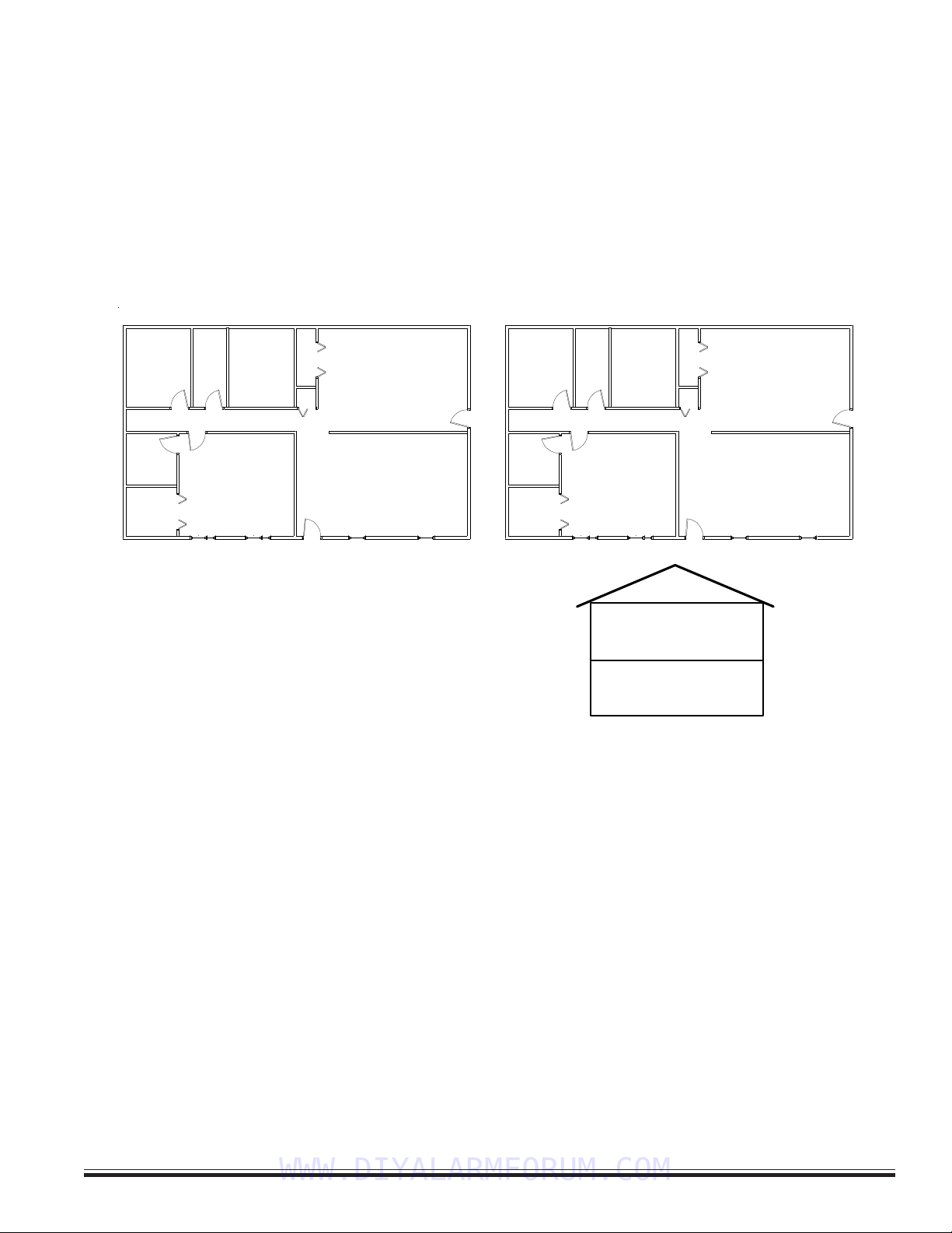
Legend
- Main Control
- Audible Alarm
- Smoke Detector
- Contact
- Keypad
M
A
S
C
K
Bedroom 1Bedroom 2
Bedroom 3 Living Room
Kitchen / Dining
TYPICAL BURGLARY INSTALLATION LAYOUT
M
A
K
Bedroom 1Bedroom 2
Bedroom 3 Living Room
Kitchen / Dining
TYPICAL FIRE INSTALLATION LAYOUT
M
A
K
C
CCCCC
S
SS
S
Basement
First Floor
All perimeter openings below 18" should be provided with protection.
A Smoke Detector shall be located in each sleeping area and between
the sleeping areas and the main living area.
Early warning fire detection is best achieved by the installation of fire
detection equipment in the location shown above.
In homes basements or multiple levels at least one smoke detector
shall be on each level.
WWW.DIYALARMFORUM.COM
M1EZ8 Installation and Programming
Page 8 [Effective w/Firmware 4.3.6]
NOTE: Refer to the section ‘Data Bus E.O.L. Termination’ for information on multiple homerun cables. NEVER SPLICE OR
CONNECT WIRE WITH CONTROL POWER ON. Minimum cabling should be four conductor 22 or 24 gauge. Maximum resistance per wire is
25 Ohms. Device placement beyond 1000' is not recommended.
1.4 Control Wiring
Zone Inputs (1 thru 8 on main board, 17 thru 208 via expanders)
Zones Z1 thru Z8 are on the main board, others are in groups of 16, starting with Z17. Each 2 zones share a common
negative terminal. A zone may be programming for EOL resistor supervision (Default), or normally closed/normally open
without a resistor. In addition, Burglar and Keyswitch zones may be programmed for EOL with Security Alert on Short, or EOL
with Security Alert on Open/Short, also referred to as a Four (4) State Zone (firmware 4.3.5 or later). If EOL resistors are used,
they should be placed at the furthest most remote end of the detection device wiring. EOL zones permit a combination of
N.C. (normally closed) or N.O. (normally open) devices. Using voltage meter probes across the zone and com terminals, a
non-violated EOL zone will measures approx. 7.0 VDC. An open circuit will be approx. 13.8 VDC. A shorted circuit will be
0 VDC. The Keypad also provides the ability “Menu 8 “System Diagnostics” to view zone voltage.
ELK-M1KP
1
See Note about
Data Bus
Termination
6
BLACK
WHITE
GREEN
RED
Keypad
Wiring
Assembly
Data Bus Cable
CAT5 or CAT6 Recommended
Optional programmable Zone Input from Keypad
Hookup Diagram for Keypad
Splice 6 Pin Keypad Wiring Assembly to the Data Bus cable using ELK-900-2 "B" Connectors.
BROWN
Optional programmable Output from Keypad
Keypad 1
The optional Zone Input # or Output # is
determined by the Keypad Address.
Load (50mA max)
I.E. LED, Relay
-
+
To BLACK (Neg) Wire
To BROW N W i r e
N.C. N. O.
2200
Ohm
EOL
To BLACK (Neg) Wire
BLUE
To B LUE W i r e
NOTE: The first batch of M1KP Keypads provided a switched
negative (pull to ground) output. Connect per diagram above.
These units have the letter "E" at the end of the ID number on the
lower back side of the board. EG: PC096EBoards with a letter
"F" or later provide the output as a switched positive.
Load (50mA max)
i.e. Relay, LED
-
+
To Red (Pos) Wire
To Brown Wire
KP Zone Output
Address # #
1 193 193
2 194 194
3 195 195
4 196 196
5 197 197
6 198 198
7 199 199
8 200 200
KP Zone Output
Address # #
9 201 201
10 202 202
11 203 203
12 204 204
13 205 205
14 206 206
15 207 207
16 208 208
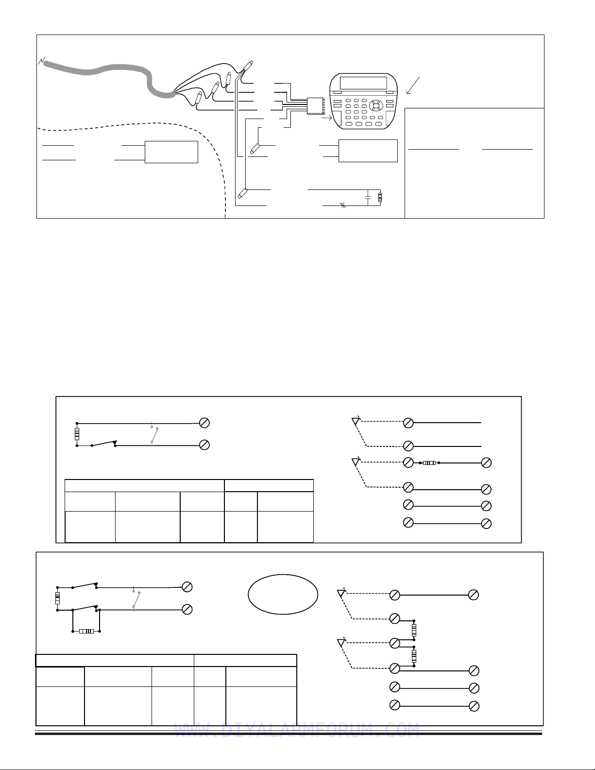
Optional Four (4) State Zone Wiring (2 series resistors w/ N.C. contacts)
Zone
Input
Neg.
N.C. Alarm
Contacts
2200 Ohm
EOL Resistor
2200 Ohm
EOL Resistor
N.C. Tamper
Contacts
Pos.
Neg.
Fig 2: Powered PIR, Glassbreak, etc. with Tamper
N.C. N.O.
Contact
2200
Ohm
EOL
Zone Input
Neg.
Tamper Contact
N.C.
Alarm
Contact
Diagnostic Table
Short ~
2.2k Ohms
4.4k Ohms
Open ~
0 - 3.9 Volts
4.0 - 7.3 Volts
7.4 - 11 Volts
11.1 - 13.8 Volts
Zone
Resistance
Approx. Zone
Voltage Reading
Alarm
-
Alarm
Alarm
Armed
Sec. Alert/Tamper
Ready
Not Ready
Sec. Alert/Tamper
Disarmed
Condition When:
0 - 72
73 - 159
160 - 220
221 - 255
A to D
Value
Fig 1: N.C. Alarm Contact
(Unpowered) with N.C. Tamper
Program Zone for EOL Wiring
Type 4 - Supervisory on Open
This feature
requires Firmware
2.3.5 or later.
2200 Ohm
EOL
Traditional Three (3) State Zone Wiring (1 series resistor)
Wire in Series with zone
input or use another zone.
Neg.
N.C. Alarm
Contacts
2200 Ohm
EOL Resistor
N.C. Tamper
Contacts
Pos.
Neg.
Powered Motion, PIR, Glassbreak, etc.
N.O.
Contact
2200
Ohm
EOL
Zone Input
Neg.
N.C.
Alarm
Contact
Diagostic Table
Short ~
2.2k Ohms
Open ~
0 - 3.9 Volts
4.0 - 8.8 Volts
8.9 - 13.8 Volts
Zone
Resistance
Approx. Range
of Zone Voltage
Alarm
-
Alarm
Armed
Not Ready
Ready
Not Ready
Disarmed
Condition When:
0 - 72
73 - 170
171 - 255
A to D
Value
Zone
Input
Alarm Contact
WWW.DIYALARMFORUM.COM

M1EZ8 Installation and Programming Page 9
[Effective w/Firmware 4.3.6]
Two-Wire Smoke Zones (Zone 8)
To enable the use of two-wire smoke detectors on Zone 8, move Jumper JP1 to the 2 wire smoke position. Go to the installer
programming mode, Menu 05 - Zone Definitions, and program Zone 8 as a Fire zone (Def=10). Program the Wire Type as a 6.
NOTE Use only compatible two-wire detectors as listed on the front label of the control. Do not mix brands. The
maximum number of detectors is also listed on the front label. When jumper JP1 is set for two-wire operation, a 680
Ohm EOL resistor (furnished in the hardware pack) must be used instead of the 2,200 Ohm. Maximum wire resistance
must not exceed 60 Ohms.
Switched Power Connection (+VSMK)
Four-wire smoke detector and other devices that require a temporary power disruption in order to reset or unlatch from the
alarm state (i.e. smoke detectors, etc.) should be connected to the +VSMK 12 Volt DC switched power terminal. When a
smoke reset is performed, the operating voltage to these devices is momentarily interrupted.
Auxiliary Power Connections (+VAUX)
Motion detectors, glass breaks, etc. and other devices requiring unswitched 24-hour power should be connected to one of the
auxiliary terminals, +VAUX. All negative terminals on the terminal strip are at the same reference and may be used whenever
a common (circuit ground) negative is required. Use caution when wiring the control to distribute the load devices among the
supply and the negative terminals evenly. NOTE: Circuit ground refers to any negative terminal connection on this control.
This does not refer to earth ground or to the common terminal of the relay output.. These are not at the same voltage
potential and should not be wired so that they are electrically connected to a negative.
PTC (Positive Temperature Coefficient) Circuit Breakers
The +VAUX Auxiliary power and J16 power output terminals are protected against shorts and overloads by a 1.25A PTC. A PTC
is a solid state, auto-restoring type of circuit breaker. The +VSMK Switched (Smoke) power output is protected by a 1.1A PTC.
The +12VKP Keypad power output is protected by a 1.25A PTC. The alarm output is protected by a 1.25A PTC. NOTE:
Sometimes it may be necessary to remove power (unplug the outputs) for approx. 20 seconds after a short, to allow the
PTC to reset. Even if the short is no longer present, the remaining residual current draw may be so high that the PTC
cannot determine that the short is gone. If the PTC re-trips, check the field wiring and repair.
Transformer Primary Power Input (AC)
The control is powered by a 16.5 VAC, 40 min. VA, UL Listed Class II (power limited) transformer (ELK-TRG1640). The
specified sized and rated transformer must be used to operate this control. The transformer must be connected to a 120 VAC,
24-hour outlet not controlled by a switch other than an approved overcurrent protection device.
Connect the transformer to the AC Terminals using 16 to 18 gauge minimun wire. Do not exceed 50 feet between the
transformer and the control or run the AC power in a multiconductor with other system circuits. Leave the transformer
unplugged as well as the standby battery until all other connections have been made.
Standby Battery Connection
Connect the BLACK wire to the Neg (-) terminal on the battery, the connect the RED wire to the Pos (+) terminal on the battery.
The control is designed to operate with and recharge a 12 volt, sealed lead acid battery from 5Ah up to 18 Ah for backup of the
primary power supply. The control maintains a float charge for the battery of 13.8 VDC at 100 mA. This is in addition to the
continuous output of 1.5 Amps that the power supply maintains (see maximum current drains for UL Listed Systems).
CAUTION: Do not reverse the battery leads! The control has special circuitry which helps protect it from battery reversal
damage for short durations. However, prolonged reversal of the battery leads may cause permanent damage. A reverse
battery warning LED is located to the left of the power On/Off switch. If this light is ON, turn the power off immediately
and correct the battery lead connections.
STATUS
UL Listed Transformer,
Class II, 16.5VAC, 45VA.
i.e ELK-TRG1640
Do not connect to a
switched outlet.
POWER
Sealed Lead Acid Battery
12Volt - 5Ah min. (ELK-1250)
NOTE: See UL requirements for
standby times and battery sizes.
The control is capable of
charging up to an 18Ah battery.
Test battery regularly with
ELK-BLT Battery Life Tester.
Replace every 3-5 years
BATTERY
RED BLK 16V XFMR
AC AC
Status LED:1 blink = Normal Operation.
2 fast blinks = Bootloader mode.
4 fast blinks = Initializing EEPROM memory.
5 fast blinks = Memory/Operation overflow.
Power LED is ON when AC Voltage is present.
12V Battery
WWW.DIYALARMFORUM.COM
M1EZ8 Installation and Programming
Page 10 [Effective w/Firmware 4.3.6]
AC Failure, Low Battery, and Automatic Low Voltage Shutdown
During an AC power failure the battery automatically takes over and AC Fail trouble annunciates at the keypad. The
communicator can be programmed to report AC Fail to the Central Station after a time delay (see Menu 12, System Option 01).
If the battery voltage falls below 11.2 VDC a Low Battery Trouble condition will occur. The communicator can be programmed
to report Low Battery to the Central Station. The battery will continue to run the control until its voltage reaches 10.5 VDC, at
which time the control will disconnect and shut down to prevent a false alarm and damage to the battery. The AC Fail trouble
display will clear if the AC restores. However, the Low Battery Trouble requires a manual or automatic battery load test before
it will clear. An automatic battery load test is performed every 24 hours. See Section 2.2 for powering up the control.
Telephone Line Connection (R1,T1,T,R)
The telephone interface is connected by the use of an approved RJ-31X interconnect jack. This device allows the subscriber
to disconnect the control/communicator from the public switched telephone network in the event of a malfunction. The control
is equipped with line seizure so that the premises telephone service is interrupted during communication to the central
station. Connection to the approved jack is done with a RJSET cord which connects the control terminals to the RJ31X jack.
HELPFUL HINT: The telephone cord can be supervised back to the RJ31X block or Telco demarcation block by installation of
a EOL resistor across the Orange and Blue wires (terminals 2 and 7 on the RJ31X jack). Back inside the control, connect the
Orange and Blue leads from the RJ cord to any 24hr Burglar zone input.
Outputs
There are 12 outputs on the main board. In programming these are numbered Out2, Out3, and Out 7 thru 16. The total
outputs may be expanded utilizing output expander boards connected to the RS-485 4-wire Keypad data bus. The Alarm
Output (Out 2) trips when any alarm is activated. All others must be enabled through the RP Rules Programming and can be
triggered by multiple conditions “events”. Do not exceed the current limits on voltage only outputs.
Output 2 is a traditional Alarm output. It is factory set to produce alarm siren sounds into standard 8 Ohm speakers (never go
below a total connected load of 4 Ohms). It can be alternately programmed to produce voltage only (12VDC) for driving self-
contained sirens or siren driver boards
Output 3 is a Single Pole Double Throw Relay with form “C” contacts (Com, N/O, and N/C).
Outputs 7, 8, 9, 10, 11, 12, 13, 14, 15, and 16 are low current, positive (+) voltage only, for driving LEDs, relays, etc. Outputs 4,
5, and 6 ARE NOT available from the main board. They can only be accessed with a data bus Output expander set to
address 1. This expander will replicate all the main board outputs, including outputs 4, 5, and 6.
Earth Grounding
Tests and studies have determined that the best results against lightning and transients are obtained by isolating the control
from ground. Do NOT connect any of the terminals, especially the Neg. terminals to earth ground. However, ancilliary devices
such as the ELK-950 Surge Protector on the incoming Telephone circuit are still recommended.
Keypad & Expanders on the RS-485 Data Bus (+12VKP, Data A, Data B, Neg)
Keypads and data bus expander devices connect to the four terminals marked +VKP, Data A, Data B, and Neg. The keypad
plug-in wire harness color code is: Red +VKP, Green Data A, White Data B, and Black (-) Neg. The +12VKP power terminal is
protected by an auto reset PTC device. In the event of a short circuit or malfunction, power will be removed from all devices
until the problem is resolved.
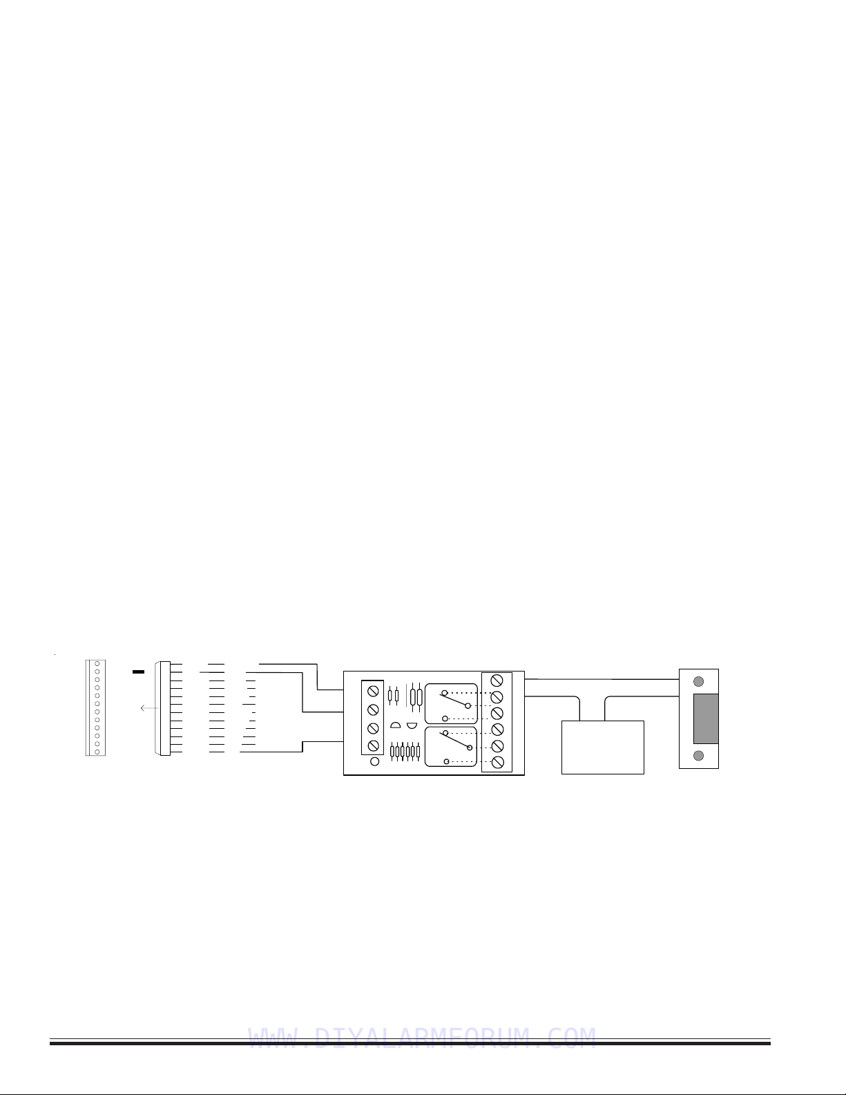
Using Output 7 (low current) with a sensitive relay to switch 24V AC to a Door Strike
24V AC
Transformer
+-
Door
Strike
ELK-924
POS
NEG
-T+T
N/OCOMN/C
D3
24V OPEN
N/OCOMN/C
+12V
NEG
16
15
14
13
12
11
10
9
8
7
J16
OUTPUTS
Programmable Outputs (J16) OUT 7 - 16 are +12V switched
positive general purpose outputs rated at 50mA.
+12V Red
Black
White
Green
Brown
Blue
Yellow
Violet
Pink
Tan
Orange
Grey
+VAUX
NEG
OUT 16
OUT 15
OUT 14
OUT 13
OUT 12
OUT 11
OUT 10
OUT 9
OUT 8
OUT 7
WWW.DIYALARMFORUM.COM

M1EZ8 Installation and Programming Page 11
[Effective w/Firmware 4.3.6]
Data Bus E.O.L. Termination - VERY IMPORTANT!
The control features a true RS-485 “differential” data bus operating at 38,400 bits per second. This is relatively high speed by
industry standards and ensures fast, accurate communications. With this speed, EOL data bus terminating resistors are
required to eliminate the possibility of reflection errors caused by varying cable lengths. Every data bus device; keypad, zone
expander, etc. and the control board has a built-in bus terminating resistor (120 Ohm) which is installed (activated) via a 2 pin
header/jumper (2 Gold Pins). The hardware pack includes two black shorting caps. When one of the shorting caps is placed
on the two gold pins, it installs (activates) the 120 Ohm terminating resistor across Data Lines A & B. Terminating resistors
are marked JP2 on the keypads and JP1 on the expanders. From the factory, no terminating resistors are installed (activated).
WARNING! The RS-485 Data Bus must NEVER have more than 2 terminating resistors header/jumpers installed.
Ideally, there should be no more than 2 home run cables (4 wire) with daisy chained devices along each. The last device on each cable
MUST have a terminating resistor installed (activated) via the gold 2 pin header/jumpers marked JP2 on keypads, JP1 on expanders. Place a
black shorting cap (see hardware pack) onto the 2 gold pins to install a 120 Ohm resistor across data lines A & B. If there is only 1 data bus
cable place a shorting cap on JP3 of Main Board. See alternate hookups below.
For those that prefer to home run wires, use 6 or 8 conductor (CAT5 is ideal) cable. At each device, make a three way splice of the data A, the
device A wire (terminal), and a return data A1 wire (using one of the extra wires). At the control, make a two way splice of the data A1 return
wire (series connection) to the outgoing data A wire of the next cable. Repeat for the data B wire. Remember to install a terminating jumper on
the last wired device and the control JP3 ONLY! Electrically the data wires are now in series. Connect the POS (+) and Neg (-) power wires of
each device directly to the M1’s +VKP and Neg terminals. DO NOT SERIES THE POWER WIRES as this will cause unnecessary voltage loss.
The ELK-M1DBH † Data Bus Hub accepts CAT5 or CAT6 cable with RJ45 plugs on the ends and does all the work of series connecting the
DATA lines A & B. Terminate at the hub using the included RJ45 Terminating Plug in the first unused jack.
+VKP
DATA B
DATA A
NEG
EGND
ELK-M1KP
BLACK
WHITE
GREEN
RS-485 Data Bus (Max. length is 4000 ft.
Max. bus devices vary by control.)
RS-485 DATA BUS
RED
ELK-M1XIN
ELK-M1XOV
Jumper
Terminate
these two
devices.
DO NOT Jumper
Terminate these devices.
Keypad 1
ELK-M1KP
Keypad 2
ELK-M1KP
Keypad 3
Daisy Chain Connection of Data Bus Devices Using Two (2) Home Run Cables
Install Teminating Jumper
Cap on this last device
AND on the control JP3.
6conductorcables
+VKP
DATA A
DATA B
NEG
DATA
A1 A
B1 B
DATA
A1 A
B1 B
WHITE
GREEN
BLACK
RED
A
-
+
B
SPARE
PAIR
See Keypad Diagram for connection
of Optional Output and Zone Input
WHITE
GREEN
BLACK (-)
RED +12
BLUE
BROWN
6
Conductor
Cable
Keypad
DATA
A1
B1
For future
devices
A1
B1
Connect each device to the 6
conductor cable as shown.
Diagram for Daisy Chain Connection of Data Bus Devices Using 3 or More Home Run Cables.
NOTE: The power wires are parallel
connected to the +VKP & Neg terminals.
RS-485 DATA BUS
Keypad
Keypad
Keypad
ELK-M1DBH Data Bus Hub †
Mount M1DBH inside control. Connect it to the M1
Data Bus terminals using a 4 conductor cable.
J2 J4 J6 J8
J1 J3 J5 J7 J9
RJ45 Terminating Plug Insert in first unused jack and terminate the
control at JP3. DO NOT TERMINATE AT ANY OF THE DEVICES!
CAT5 Cables
Daisy Chain Connection using the ELK-M1DBH and CAT5 Cables.
RS-485 DATA BUS
8 - Brn/Wht
7 - Wht/Brn
6 - Org/Wht
5 - Wht/Blue
4 - Blue/Wht
3 - Wht/Org
2 - Grn/Wht
1 - Wht/Grn
RED +12V
BLACK (-)
GREEN (A)
WHITE (B)
BROWN
Pin1
RJ45 Plug
A1Grn/Wht
AOrg/Wht
-Wht/Brn
+Brn/Wht
BWht/Org
B1Wht/Grn
Spare
Spare
COLOR CODE for CAT5 or CAT6 Data Bus Cable
to RJ45 Plugs for ELK-M1DBH Data Bus Hub.
Pin1
Front
view
Optional programmable Zone Input from Keypad
Optional programmable Output from Keypad
Load (50mA max)
I.E. LED, Relay
-
+
To BLACK (Neg) Wire
To BROWN Wire
N.C
.
N.O
.
2200
Ohm
EOL
To BLACK (Neg) Wire
To BLUE Wire
BLUE
Keypad
Keypad
CAT5
or
CAT6
Cable
† Not evaluated by UL †† Not for use in UL Listed Installations
WWW.DIYALARMFORUM.COM
M1EZ8 Installation and Programming
Page 12 [Effective w/Firmware 4.3.6]
Setting the Data Bus Address and Enrolling Device(s) into the System
Keypads and expander devices communicate over the RS-485 4-wire data bus. Each device must have a unique address
setting (from 1 to 16) within it's device type. Keypads are TYPE 1, input (zone) expanders TYPE 2, output expanders TYPE 3, etc.
The purpose of device types is so that the address numbers can be re-used in each different device type. It’s OK to have a
Keypad, Zone Expander, and Output Expander all set to address 2 and on the same data bus since each device is a different
device type. It is NOT OK to have duplications of addresses within the same device type. I.E. Multiple keypads on the same
control cannot be set to 'like' addresses.
ADDRESS: From the factory all keypads are set to address 1. Valid addresses are 1 to 16. The first keypad on the system
(Keypad 1) is automatically enrolled upon power up. Each additional keypad must be assigned a unique address and then
manually enrolled from “Menu 1 - Bus Module Enrollment”. (See Menu 01, for complete instructions on Bus Module Enrollment)
1. Press and hold the " * " key, followed by the F5 key . HOLD BOTH keys pressed for 5-10 seconds or until the LCD displays:
Exit when done. F1 Set Addr. (This is Keypad setup mode)
NOTE: An alternate method is to remove power from the keypad and then power up while holding any key pressed.
2. Press the F1 key to display the current address setting.
3. Set the desired address (from 1 to 16) by using the Up or Down arrow keys.
4. Press the Exit key twice when done.
12345678901234567890123456
1
234567890123456789012345
6
1
234567890123456789012345
6
1
234567890123456789012345
6
1
234567890123456789012345
6
1
234567890123456789012345
6
1
234567890123456789012345
6
1
234567890123456789012345
6
1
234567890123456789012345
6
12345678901234567890123456
Auth. Required
Enter Valid Pin
12345678901234567890123456
1
234567890123456789012345
6
1
234567890123456789012345
6
1
234567890123456789012345
6
1
234567890123456789012345
6
1
234567890123456789012345
6
1
234567890123456789012345
6
1
234567890123456789012345
6
12345678901234567890123456
01-Bus Module
Enrollment
ENROLLING:
1. Press the ELK key, then 9 (or scroll up) to display 9 - Installation Programming. Press the RIGHT
arrow key to select this menu. The Installer Program Code must be entered to access this menu.
2. Enter the Installer Program Code. (The default code is 172839)
3. The first Installer Programming menu displayed will be "Bus Module Enrollment"
4. Press the RIGHT arrow key to select this menu. "Enrolling Bus Modules" will display
5. After a few seconds the display will show the total Bus Modules that are enrolled. To view the
enrolled devices and/or remove a device press the RIGHT arrow key next to the word Edit.
6. Press the * or Exit keys to exit Installer Programming.
12345678901234567890123456
1
234567890123456789012345
6
1
234567890123456789012345
6
1
234567890123456789012345
6
1
234567890123456789012345
6
1
234567890123456789012345
6
1
234567890123456789012345
6
1
234567890123456789012345
6
1
234567890123456789012345
6
12345678901234567890123456
XX Bus Modules
Enrolled, Edit rr
rr
r
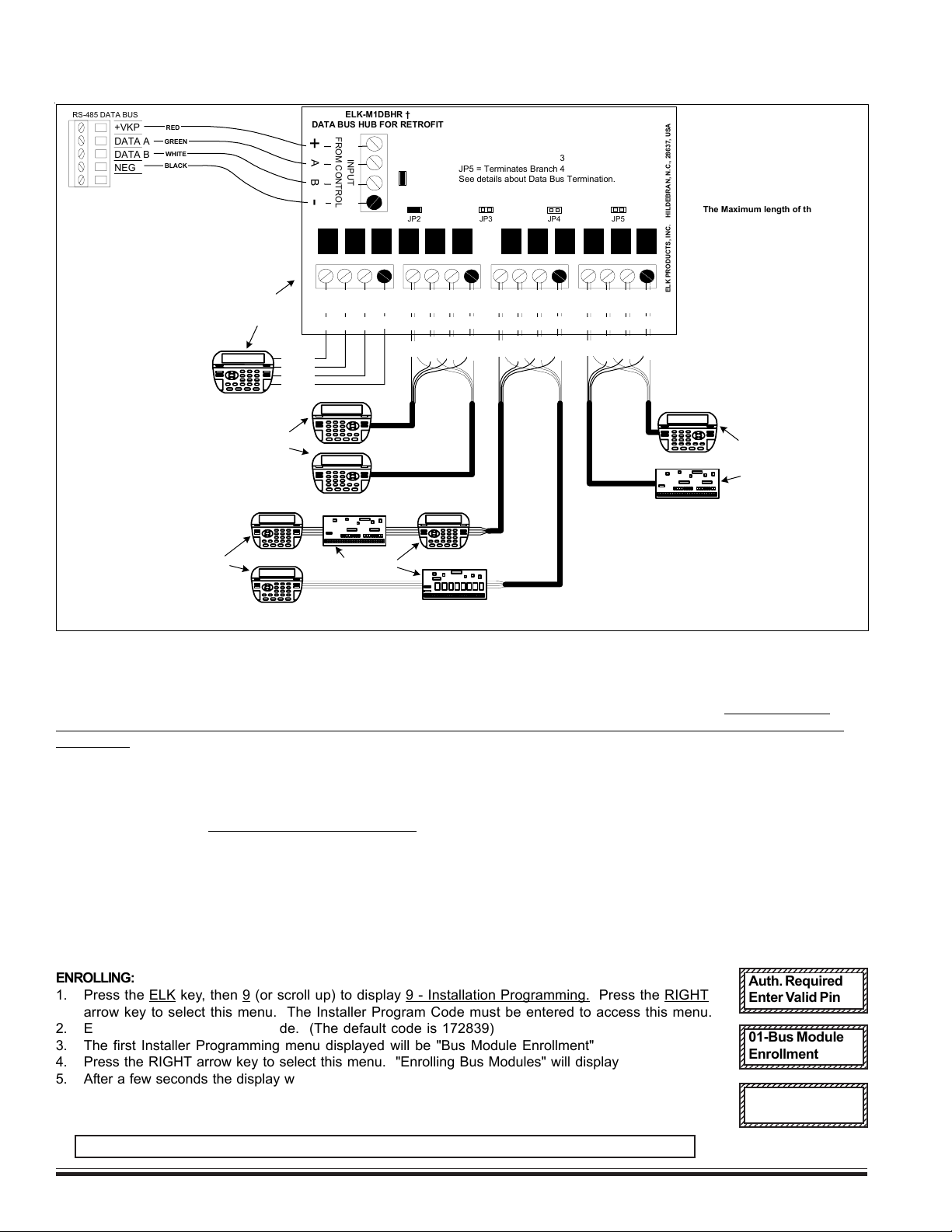
The ELK-M1DBHR † "Active" Data Bus Hub Retrofit splits the Controls' main RS-485 Data Bus into 4 managed RS-485 branches. Each branch
can have 2 parallel home run cables for a total of 8 home runs. The last (end of line) device on each home run should be jumper terminated to
insure proper operation and supervision.
JP1
Terminating Jumpers (JP1 - JP5)
JP1 = Terminates Input from Control
JP2 = Terminates Branch 1
JP3 = Terminates Branch 2
JP4 = Terminates Branch 3
JP5 = Terminates Branch 4
See details about Data Bus Termination.
ELK-M1DBHR †
DATA BUS HUB FOR RETROFIT
ELK PRODUCTS, INC. HILDEBRAN, N.C., 28637, USA
JP2 JP3 JP4 JP5
+VKP
DATA B
DATA A
NEG
RS-485 DATA BUS
BLACK
RED
GREEN
WHITE
AB-
+
INPUT
FROM CONTROL
The Maximum length of the
RS-485 Data Bus or any single
Branch is 4000 ft.
Max. devices varies by product.
+VKP protected with 1.25A PTC
Mount M1DBHR inside control.
Connect it to the Data Bus terminals
using a 4 conductor cable.
RED
GREEN
WHITE
BLACK
A
+B-
DATA BUS
BRANCH 1
RED
GREEN
WHITE
BLACK
Keypad
A
+B-
DATA BUS
BRANCH 2
Keypad
RED
GREEN
WHITE
BLACK
Keypad
Single Keypad /Bus Device:
If only one (1) Keypad or Bus Device
is connected to a branch (# 1 in this
example), place terminating jumper
on the Keypad/Bus Device AND on
JP2 of the M1DBHR.
Two Keypad /Bus Devices:
If two (2) Keypad/Bus Devices are connected to
a branch (#2 in this example), place terminating
jumper on both Keypads/Device and REMOVE
jumper JP3 on the M1DBHR.
Multiple Keypads/Bus Devices
(Series Connected):
If more than two (2) Keypad/Bus
Devices are connected to a
branch (#3 in this example), they
MUST be series connected on no
more than 2 homerun wires.
Place terminating jumpers on
LAST device connected to each
homerun. REMOVE jumper JP4
on the M1DBHR.
ELK-M1XIN
ELK-M1XOV
Jumper
Terminate
these two
devices.
DO NOT Jumper Terminate
these devices.
ELK-M1KP
Keypad
KeypadKeypad
RED
GREEN
WHITE
BLACK
A
+B-
DATA BUS
BRANCH 3
A
+B-
DATA BUS
BRANCH 4
ELK-M1XIN
Jumper
Terminate
these two
devices.
One Keypad and one
Zone Expander:
When two (2) Bus
Devices are connected
to a branch (#4 in this
example), place
terminating jumper on
both Bus Devices and
REMOVE jumper JP3
on the M1DBHR.
Jumper
Terminate
these two
devices.
Keypad
JumperTerminate
this device AND JP2
on the M1DBHR.
DO NOT Jumper JP3. DO NOT
Jumper JP5
DO NOT Jumper JP4.
This diagram illustrates the M1DBHR Hub as a single
branch on a Control. Terminate JP3 on Control and JP1
on the M1DBHR. If a second hub is wired to the Control
terminate JP1 on the hubs but DO NOT terminate JP3 on
Control. NEVER place more than two (2) terminating
jumpers on any branch of the RS-485 Data Bus!
Diagram for Home run wiring using M1DBHR Active Data Bus Hub
† Not evaluated by UL †† Not for use in UL Listed Installations
WWW.DIYALARMFORUM.COM

M1EZ8 Installation and Programming Page 13
[Effective w/Firmware 4.3.6]
2.1 Introduction
For best operation during bench testing, all zones should be terminated with end of line resistors and the correct transformer
and battery should be connected to the unit. The control comes with factory default programming, allowing it to be bench
tested prior to installation. The factory default code for user 1 is 3456. This code is authorized to operate all user related
features of the system. The control is designed to accommodate the grouping of specific zones into partitions called areas
and by default, all zones are assigned to area #1. This is the most common mode in which the system operates. This section
of the manual gives an overview of powering up and basic keypad functioning.
2.2 Powering Up (One Keypad)
After all other connections have been made and checked thoroughly, the controls AC transformer and battery may be
connected. Upon power up the control will perform self-diagnostics and auto-enroll the first keypad (Keypad Address #1). Any
additional keypads or expanders must be manually enrolled using Installer Level Programming. See “Menu 01 - Bus Module
Enrollment”.
NOTE: It is very important to make certain that every keypad, input expander, output expander, or any other data bus
device be assigned a unique data bus address within its type. See “MENU 01 - Bus Module Enrollment” for instructions
on setting keypad and expander addresses.
2.3 User Codes and Authorities
The control has 99 user passcodes plus one installer passcode. Each user code may be assigned specific authorities as to
what it is allowed to do. The authorities are assigned from the Installer level programming, however the code numbers and
user name is assigned from the keypad user menu 6 - Change User Codes. Only a Master authority level code or the
Installer code is allowed to access keypad user menu 6. The User’s Guide contains a description of panel
operations accessible to the user codes. Control operations accessed by the installer passcode are slightly different.
The Factory Default Code for User Code 1 is: 3 4 5 6 (Master Code)
(If the six digit code option is enabled, User Code 1 default will then be: 1 2 3 4 5 6)
The user code may be used for functions in a specific area or system-wide. Some options may be performed at any time,
even while the control is fully or partially armed. The menu system is designed to be next-step-oriented. After a brief
explanation of the options, the user should be able to begin operating the system immediately. For purposes of discussion,
the installer and the end consumer are both considered users, but have different capabilities.
2.4 Installer Program Code and Authorities
The installer code can access all the keypad user menus, including of course menu 9 - Installation Programming. The
Installer code also has limited arm/disarm privileges. It may be used to arm any area and may be used to disarm any area,
so long as that area was armed specifically by the installer code. The Installer code cannot disarm if an area was armed by
any user code. The Installer code may be used to silence 24hr alarms or a Burglary alarm in an area that was armed by the
installer or in an area that is not armed. The installer code may also be used to silence a trouble condition in a disarmed
area. See User’s Guide for a full description of arming and disarming procedures.
The Factory Default Installer Program Code is: 1 7 2 8 3 9
Section 2 - Operating the System
WWW.DIYALARMFORUM.COM

M1EZ8 Installation and Programming
Page 14 [Effective w/Firmware 4.3.6]
Ready Light - This light is ON when all burglar zones are secure and the system is OK for arming. If this light is OFF, one or more zones are
violated (not secure). For maximum security, all zones should be secured before the system is armed.
If FLASHING, one or more force-armable zones are violated. Force arming temporarily excludes violated zone(s) from the system. However, if
a force armed zone becomes secure while the system is armed, it will automatically restore to service. This is handy for a garage door. The
system may be armed with the door up, but once the car is backed out and the door is closed, it will become secured.
Armed Light- This light will be ON when the system is armed. The mode of arm will be indicated by the LCD display and the Exit or Stay
lighted pushbuttons. This light will be OFF when the system is disarmed.
Exit Key - This lighted key may be programmed for single or double press arming to the AWAY (not occupied) mode. If the Exit light is ON the
system is armed and all perimeter sensors and interior motions are active. The Away key may be pressed during the exit delay time t to
convert from Away mode to Away Vacation mode. The Away Vacation mode is primarily for use with the Whenever/And/Then Rules program-
ming of Elk-RP to invoke long term energy savings.
Stay Key - This lighted key may be programmed for single or double press arming to the STAY (occupied) mode. If the Stay light is ON the
system is armed and all interior zones are excluded (bypassed). Only perimeter doors and windows are active in the Stay mode. This key
may also be programmed to change to other Stay modes such as: Stay Instant, Stay Night, and Stay Night Instant. Since interior zones are
automatically excluded once the Stay mode is activated, the M1 allows this key to Stay arm even while one or more interior zones are
violated, provided they are programmed for “force arming”. The Stay Night mode re-activates any interior night zones. To prevent a false
alarm the control will not allow change to the Stay Night mode when a interior night zone is violated unless it is programmed for “Force arm”.
Chime Key - Chime produces an audible tone alert whenever certain doors, windows, or other selected zones are violated. There are two
selections: Tone only and Off. Whenever Chime in On the Chime key will be illuminated. In the programming mode the Chime key also
functions as an insert character key for text programming.
Bypass Key - Pressing this key followed by a zone number and the bypass key again will exclude or bypass the selected zone. This
key may also be used to delete a character during text programming. When the Bypass key is lit, one or more zones are bypassed.
* Key - This key serves as a clear or reset key. If an error is made while entering digits, pressing this key clears the error. Three presses is
a master clear.
# Key - This key is currently a duplicate of the Bypass key.
Numerical Keys - These keys are used for entry of passcodes, programming, etc. Keys 2 - 9 also have an assigned alpha character
which are used for entering text.
Arrow Keys - The ELK and arrow keys have powerful functionality used for both normal operation and programming. Pressing the ELK
key displays relative information according to each application. The arrow keys allow scrolling through all available options. The user can
activate or select the displayed option by pressing the right arrow key. Once an option has been selected, the user may be prompted for
a passcode. Additional sub-menu options may appear to assist. The user may return to the status screen by pressing the * key.
2.5 Keypad Overview
WWW.DIYALARMFORUM.COM
M1EZ8 Installation and Programming Page 15
[Effective w/Firmware 4.3.6]
Access to menus 1 to 5 can be restricted via programming to only Users that have “User Code Option 8” set. Menus 6, 7, and
8 required a Master or Installer Code. Menu 9 requires the Installer Code. Press ELK to begin, then press the UP or DOWN
arrow key to select a menu. Enter a code if prompted. To select a menu press the RIGHT arrow key.
Keypad Menus
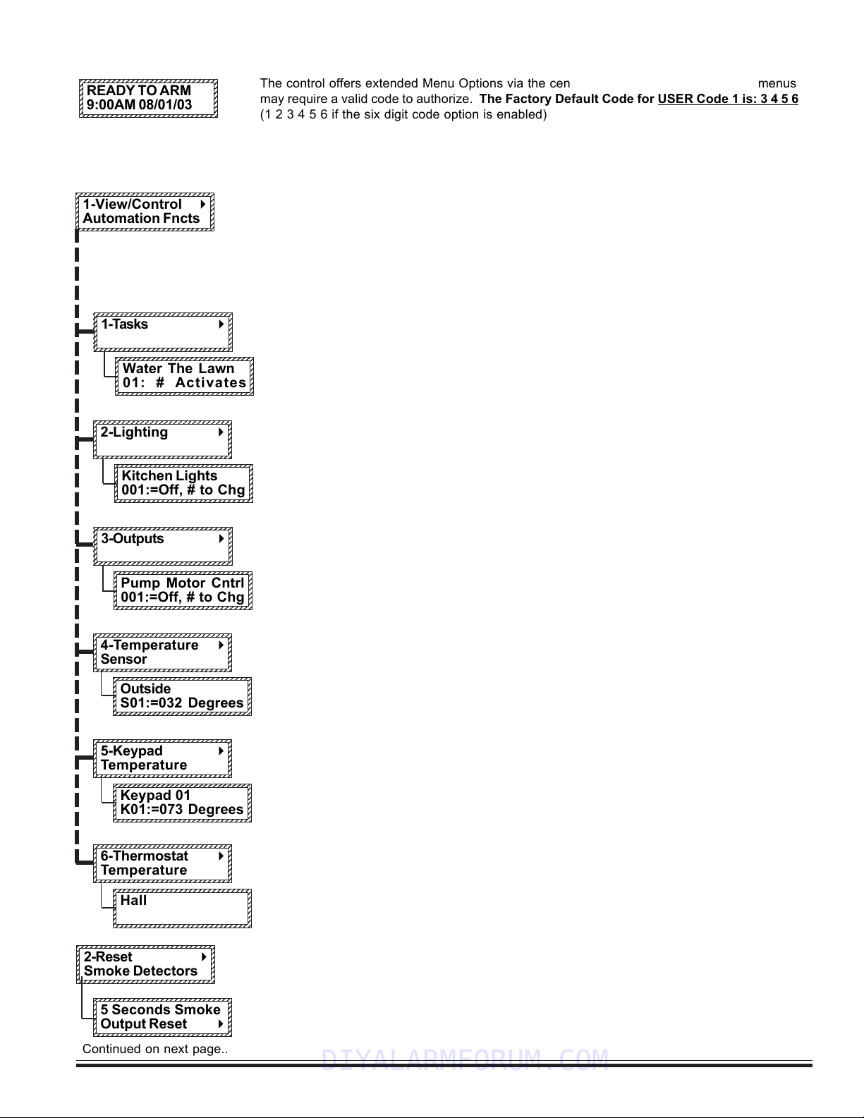
Allows viewing or controlling of the automation functions such as Tasks, Lighting, Outputs,
Temperature Sensor, Keypad Temperature, and Thermostats. Press the RIGHT arrow key to
select, then choose the desired function using the UP or DOWN arrow keys.
NOTE: The automation functions must be assigned and named using the ELK-RP software.
In most cases they cannot do anything unless they have been written into one of the
“Whenever/And/Then” automation rules.
Tasks are like 1 button macros, performing multiple jobs with one push. To activate a task
press the RIGHT arrow key and press UP or DOWN to scroll through the list of available tasks.
To jump directly to a particular task, enter it’s two digit number. Once the task is displayed, all
it takes to activate it is to press the # key. A rule to use the “Water the Lawn” task might be:
WHENEVER “Water the Lawn” IS ACTIVATED THEN TURN ON Valve 19 FOR 5 MINUTES, etc.
Lighting allows the individual control of lights and/or appliances which have been assigned
through the ELK-RP software. Press the RIGHT arrow key to select Lighting, then press the
UP or DOWN arrow keys to scroll through the list. If you know the three digit number, you may
enter it to jump directly to that Lighting/Appliance. The current state of the unit will be
displayed. Press the # key to toggle (change) the unit from on > off or from off > on.
Outputs might be relays or voltages used to actuate something like a motor, fan, pump, etc.
Outputs can be turned on or turned off from this menu. Press the RIGHT arrow key to select
Outputs, then press the UP or DOWN arrow keys to scroll through the list. If you know the
three digit number, you may enter it to jump directly to that Output. The current state of the
output will display. Press the # key to toggle (change) the output from on > off or from off > on.
Remote “Zone” Temperature Sensors can be read from this menu. Press the RIGHT arrow
key to select this menu, then press the UP or DOWN arrow keys to scroll through the list of
available sensors. To jump directly to a particular sensor enter it’s two digit number. The
current temperature will be displayed. Press the * key to exit.
Keypad Temperature Sensors can be read from this menu. Press the RIGHT arrow key to
select this menu, then press the UP or DOWN arrow keys to scroll through the list of available
keypads. To jump directly to a particular keypad enter it’s two digit number. The current
temperature at the keypad will be displayed. Press the * key to exit.
Thermostats can be read from this menu. Press the RIGHT arrow key to select this menu,
then press the UP or DOWN arrow keys to scroll through the list of available thermostats. To
jump directly to a particular thermostat enter it’s two digit number. The current temperature at
the thermostat will be displayed. Press the * key to exit.
Used for resetting latched smoke detectors after a fire alarm activation..
Press the RIGHT arrow key to actuate the Reset Smoke Detector feature. This causes the
power to smoke detectors to be removed for 5 seconds. During this time all fire zones will be
ignored to keep an accidental alarm from occurring.
1234567890123456789012345678901
1
23456789012345678901234567890
1
1
23456789012345678901234567890
1
1
23456789012345678901234567890
1
1
23456789012345678901234567890
1
1
23456789012345678901234567890
1
1
23456789012345678901234567890
1
1
23456789012345678901234567890
1
1
23456789012345678901234567890
1
1234567890123456789012345678901
1-View/Control r
Automation Fncts
123456789012345678901234567890
1
2345678901234567890123456789
0
1
2345678901234567890123456789
0
1
2345678901234567890123456789
0
1
2345678901234567890123456789
0
1
2345678901234567890123456789
0
1
2345678901234567890123456789
0
1
2345678901234567890123456789
0
123456789012345678901234567890
2-Reset r
Smoke Detectors
123456789012345678901234567890
1
2345678901234567890123456789
0
1
2345678901234567890123456789
0
1
2345678901234567890123456789
0
1
2345678901234567890123456789
0
1
2345678901234567890123456789
0
1
2345678901234567890123456789
0
1
2345678901234567890123456789
0
123456789012345678901234567890
READY TO ARM
9:00AM 08/01/03
Continued on next page..
123456789012345678901234567890
1
2345678901234567890123456789
0
1
2345678901234567890123456789
0
1
2345678901234567890123456789
0
1
2345678901234567890123456789
0
1
2345678901234567890123456789
0
1
2345678901234567890123456789
0
1
2345678901234567890123456789
0
123456789012345678901234567890
3-Outputs r
1234567890123456789012345678901
1
23456789012345678901234567890
1
1
23456789012345678901234567890
1
1
23456789012345678901234567890
1
1
23456789012345678901234567890
1
1
23456789012345678901234567890
1
1
23456789012345678901234567890
1
1
23456789012345678901234567890
1
1234567890123456789012345678901
Pump Motor Cntrl
001:=Off, # to Chg
123456789012345678901234567890
1
2345678901234567890123456789
0
1
2345678901234567890123456789
0
1
2345678901234567890123456789
0
1
2345678901234567890123456789
0
1
2345678901234567890123456789
0
1
2345678901234567890123456789
0
1
2345678901234567890123456789
0
123456789012345678901234567890
2-Lighting r
123456789012345678901234567890
1
2345678901234567890123456789
0
1
2345678901234567890123456789
0
1
2345678901234567890123456789
0
1
2345678901234567890123456789
0
1
2345678901234567890123456789
0
1
2345678901234567890123456789
0
1
2345678901234567890123456789
0
123456789012345678901234567890
1-Tasks r
123456789012345678901234567890
1
2345678901234567890123456789
0
1
2345678901234567890123456789
0
1
2345678901234567890123456789
0
1
2345678901234567890123456789
0
1
2345678901234567890123456789
0
1
2345678901234567890123456789
0
1
2345678901234567890123456789
0
123456789012345678901234567890
Water The Lawn
01: # Activates
123456789012345678901234567890
1
2345678901234567890123456789
0
1
2345678901234567890123456789
0
1
2345678901234567890123456789
0
1
2345678901234567890123456789
0
1
2345678901234567890123456789
0
1
2345678901234567890123456789
0
1
2345678901234567890123456789
0
123456789012345678901234567890
Kitchen Lights
001:=Off, # to Chg
123456789012345678901234567890
1
2345678901234567890123456789
0
1
2345678901234567890123456789
0
1
2345678901234567890123456789
0
1
2345678901234567890123456789
0
1
2345678901234567890123456789
0
1
2345678901234567890123456789
0
1
2345678901234567890123456789
0
123456789012345678901234567890
5 Seconds Smoke
Output Reset r
The control offers extended Menu Options via the center navigation “ELK” key. Some menus
may require a valid code to authorize. The Factory Default Code for USER Code 1 is: 3 4 5 6
(1 2 3 4 5 6 if the six digit code option is enabled)
123456789012345678901234567890
1
2345678901234567890123456789
0
1
2345678901234567890123456789
0
1
2345678901234567890123456789
0
1
2345678901234567890123456789
0
1
2345678901234567890123456789
0
1
2345678901234567890123456789
0
1
2345678901234567890123456789
0
1
2345678901234567890123456789
0
123456789012345678901234567890
4-Temperature r
Sensor
1234567890123456789012345678901
1
23456789012345678901234567890
1
1
23456789012345678901234567890
1
1
23456789012345678901234567890
1
1
23456789012345678901234567890
1
1
23456789012345678901234567890
1
1
23456789012345678901234567890
1
1
23456789012345678901234567890
1
1234567890123456789012345678901
Outside
S01:=032 Degrees
123456789012345678901234567890
1
2345678901234567890123456789
0
1
2345678901234567890123456789
0
1
2345678901234567890123456789
0
1
2345678901234567890123456789
0
1
2345678901234567890123456789
0
1
2345678901234567890123456789
0
1
2345678901234567890123456789
0
123456789012345678901234567890
5-Keypad r
Temperature
1234567890123456789012345678901
1
23456789012345678901234567890
1
1
23456789012345678901234567890
1
1
23456789012345678901234567890
1
1
23456789012345678901234567890
1
1
23456789012345678901234567890
1
1
23456789012345678901234567890
1
1
23456789012345678901234567890
1
1234567890123456789012345678901
Keypad 01
K01:=073 Degrees
123456789012345678901234567890
1
2345678901234567890123456789
0
1
2345678901234567890123456789
0
1
2345678901234567890123456789
0
1
2345678901234567890123456789
0
1
2345678901234567890123456789
0
1
2345678901234567890123456789
0
1
2345678901234567890123456789
0
123456789012345678901234567890
6-Thermostat r
Temperature
1234567890123456789012345678901
1
23456789012345678901234567890
1
1
23456789012345678901234567890
1
1
23456789012345678901234567890
1
1
23456789012345678901234567890
1
1
23456789012345678901234567890
1
1
23456789012345678901234567890
1
1
23456789012345678901234567890
1
1234567890123456789012345678901
Hallway
T01:=072 Degrees
WWW.DIYALARMFORUM.COM
M1EZ8 Installation and Programming
Page 16 [Effective w/Firmware 4.3.6]
123456789012345678901234567890
1
2345678901234567890123456789
0
1
2345678901234567890123456789
0
1
2345678901234567890123456789
0
1
2345678901234567890123456789
0
1
2345678901234567890123456789
0
1
2345678901234567890123456789
0
1
2345678901234567890123456789
0
123456789012345678901234567890
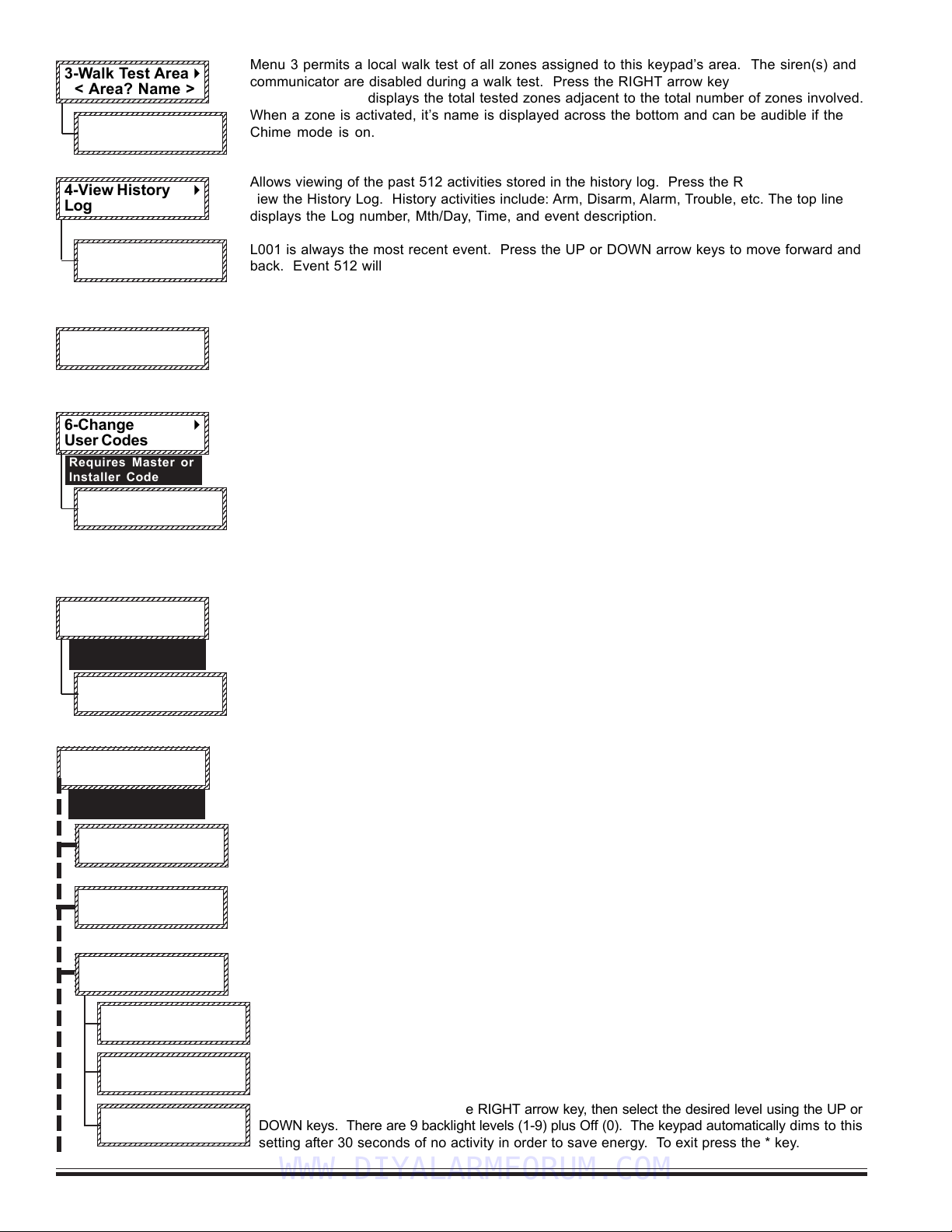
3-Walk Test Area r
< Area? Name >
123456789012345678901234567890
1
2345678901234567890123456789
0
1
2345678901234567890123456789
0
1
2345678901234567890123456789
0
1
2345678901234567890123456789
0
1
2345678901234567890123456789
0
1
2345678901234567890123456789
0
1
2345678901234567890123456789
0
123456789012345678901234567890
4-View History r
Log
123456789012345678901234567890
1
2345678901234567890123456789
0
1
2345678901234567890123456789
0
1
2345678901234567890123456789
0
1
2345678901234567890123456789
0
1
2345678901234567890123456789
0
1
2345678901234567890123456789
0
1
2345678901234567890123456789
0
123456789012345678901234567890
6-Change r
User Codes
Requires Master or
Installer Code
Menu 3 permits a local walk test of all zones assigned to this keypad’s area. The siren(s) and
communicator are disabled during a walk test. Press the RIGHT arrow key to begin a Walk
Test. The keypad displays the total tested zones adjacent to the total number of zones involved.
When a zone is activated, it’s name is displayed across the bottom and can be audible if the
Chime mode is on.
Allows viewing of the past 512 activities stored in the history log. Press the RIGHT arrow key to
view the History Log. History activities include: Arm, Disarm, Alarm, Trouble, etc. The top line
displays the Log number, Mth/Day, Time, and event description.
L001 is always the most recent event. Press the UP or DOWN arrow keys to move forward and
back. Event 512 will be the oldest event. The bottom line displays the event description, the
extended data (zone, user, etc.) and the area number (A1-A8).
Allows viewing of the current status of all zones. Press the RIGHT arrow key to select. Press
UP or DOWN to scroll through the zones or enter a three digit number to jump directly to a
particular zone. I.E. for zone 8 enter 008. Press the * key to exit.
For changing a user code and/or name for codes which have been previously enabled by the
Installer. Only a Master code OR the installer code can access this menu. Press the RIGHT
arrow key to begin. Press UP or DOWN keys to locate a user, or enter 3 digits to jump. Press
RIGHT arrow key to view the existing code. To change, enter the new code digits and listen for 3
beeps to confirm. To edit the name, press the RIGHT arrow key once, then press the DOWN
arrow key. Enter the text using the letters on the keys. I.E. For “K” press the 5 key twice. Move
RIGHT or LEFT with the arrow keys. Press Chime to insert a space. Press Bypass to erases a
letter. The UP and DOWN arrow keys shift from upper to lower case letters. Press the ELK key
to save and exit.
.
Allows an end user to change up to 20 settings incorporated into an automation rule. These
settings can be: time of day, time duration (seconds), or a numeric value. Each custom setting
has a reference number (CS) and a text description: I.E. CS01: Sprkl On 00:00 [Time] implying
a time of day setting. Press the RIGHT arrow key to begin.
Press the UP or DOWN arrow keys to locate a setting, then press the RIGHT arrow key to
select. Enter the new value and press the ELK key to save and exit.
Menu 8 consists of 8 sub-menus used for advanced system settings. Press the right arrow key
and enter a valid user code. Press the UP or DOWN arrow keys to select a sub-menu or enter
the one digit number to jump directly to any sub-menu. I.E. enter 6 to jump to 86.
To set the system clock press the RIGHT arrow key, then press the UP or DOWN arrow key to
select the day. Next, press the RIGHT arrow key to move to Date/Time setting. Enter two digits
for month, date, year, hour, and min. To exit press the * key.
To set keypad adjustments press the RIGHT arrow key. Then press the UP or DOWN keys to select
one of the three options.
1234567890123456789012345678901
1
23456789012345678901234567890
1
1
23456789012345678901234567890
1
1
23456789012345678901234567890
1
1
23456789012345678901234567890
1
1
23456789012345678901234567890
1
1
23456789012345678901234567890
1
1
23456789012345678901234567890
1
1234567890123456789012345678901
8-System r
Settings
123456789012345678901234567890
1
2345678901234567890123456789
0
1
2345678901234567890123456789
0
1
2345678901234567890123456789
0
1
2345678901234567890123456789
0
1
2345678901234567890123456789
0
1
2345678901234567890123456789
0
1
2345678901234567890123456789
0
123456789012345678901234567890
83-Keypad r
Adjustments
123456789012345678901234567890
1
2345678901234567890123456789
0
1
2345678901234567890123456789
0
1
2345678901234567890123456789
0
1
2345678901234567890123456789
0
1
2345678901234567890123456789
0
1
2345678901234567890123456789
0
1
2345678901234567890123456789
0
123456789012345678901234567890
1:Set Keypad r
Beep Tone
123456789012345678901234567890
1
2345678901234567890123456789
0
1
2345678901234567890123456789
0
1
2345678901234567890123456789
0
1
2345678901234567890123456789
0
1
2345678901234567890123456789
0
1
2345678901234567890123456789
0
1
2345678901234567890123456789
0
123456789012345678901234567890
2:Set Keypress r
Beep Volume
123456789012345678901234567890
1
2345678901234567890123456789
0
1
2345678901234567890123456789
0
1
2345678901234567890123456789
0
1
2345678901234567890123456789
0
1
2345678901234567890123456789
0
1
2345678901234567890123456789
0
1
2345678901234567890123456789
0
123456789012345678901234567890
3:Set Backlight r
Dim Level
123456789012345678901234567890
1
2345678901234567890123456789
0
1
2345678901234567890123456789
0
1
2345678901234567890123456789
0
1
2345678901234567890123456789
0
1
2345678901234567890123456789
0
1
2345678901234567890123456789
0
1
2345678901234567890123456789
0
123456789012345678901234567890
82-Not Used
123456789012345678901234567890
1
2345678901234567890123456789
0
1
2345678901234567890123456789
0
1
2345678901234567890123456789
0
1
2345678901234567890123456789
0
1
2345678901234567890123456789
0
1
2345678901234567890123456789
0
1
2345678901234567890123456789
0
123456789012345678901234567890
81-Set Sys Clock r
24hr format
123456789012345678901234567890
1
2345678901234567890123456789
0
1
2345678901234567890123456789
0
1
2345678901234567890123456789
0
1
2345678901234567890123456789
0
1
2345678901234567890123456789
0
1
2345678901234567890123456789
0
1
2345678901234567890123456789
0
123456789012345678901234567890
000of016 Tested r
A?-Violate Zones
123456789012345678901234567890
1
2345678901234567890123456789
0
1
2345678901234567890123456789
0
1
2345678901234567890123456789
0
1
2345678901234567890123456789
0
1
2345678901234567890123456789
0
1
2345678901234567890123456789
0
1
2345678901234567890123456789
0
123456789012345678901234567890
L001:01/01bb
bb
b08:00
AreaArmed 103A1
123456789012345678901234567890
1
2345678901234567890123456789
0
1
2345678901234567890123456789
0
1
2345678901234567890123456789
0
1
2345678901234567890123456789
0
1
2345678901234567890123456789
0
1
2345678901234567890123456789
0
1
2345678901234567890123456789
0
123456789012345678901234567890
001:Selbb
bb
b Prgr
< User Name >
123456789012345678901234567890
1
2345678901234567890123456789
0
1
2345678901234567890123456789
0
1
2345678901234567890123456789
0
1
2345678901234567890123456789
0
1
2345678901234567890123456789
0
1
2345678901234567890123456789
0
1
2345678901234567890123456789
0
123456789012345678901234567890
7--Automation r
Custom Settings
123456789012345678901234567890
1
2345678901234567890123456789
0
1
2345678901234567890123456789
0
1
2345678901234567890123456789
0
1
2345678901234567890123456789
0
1
2345678901234567890123456789
0
1
2345678901234567890123456789
0
1
2345678901234567890123456789
0
123456789012345678901234567890
CS01:bb
bb
b00:00Timer
Sprklr On
Requires Master or
Installer Code
Requires Master or
Installer Code
123456789012345678901234567890
1
2345678901234567890123456789
0
1
2345678901234567890123456789
0
1
2345678901234567890123456789
0
1
2345678901234567890123456789
0
1
2345678901234567890123456789
0
1
2345678901234567890123456789
0
1
2345678901234567890123456789
0
1
2345678901234567890123456789
0
123456789012345678901234567890
5-View Status r
of all zones
To set keypad beep tones press the RIGHT arrow key, then select the desired tone using the UP or
DOWN keys. There are 9 settings (0-8). When done, exit by pressing the * key.
To set key-press beep volume press the RIGHT arrow key, then select the desired volume using
the UP or DOWN keys. There are 7 volume levels (1-7) plus Off (0). To exit press the * key.
To set backlight dim level press the RIGHT arrow key, then select the desired level using the UP or
DOWN keys. There are 9 backlight levels (1-9) plus Off (0). The keypad automatically dims to this
setting after 30 seconds of no activity in order to save energy. To exit press the * key.
WWW.DIYALARMFORUM.COM
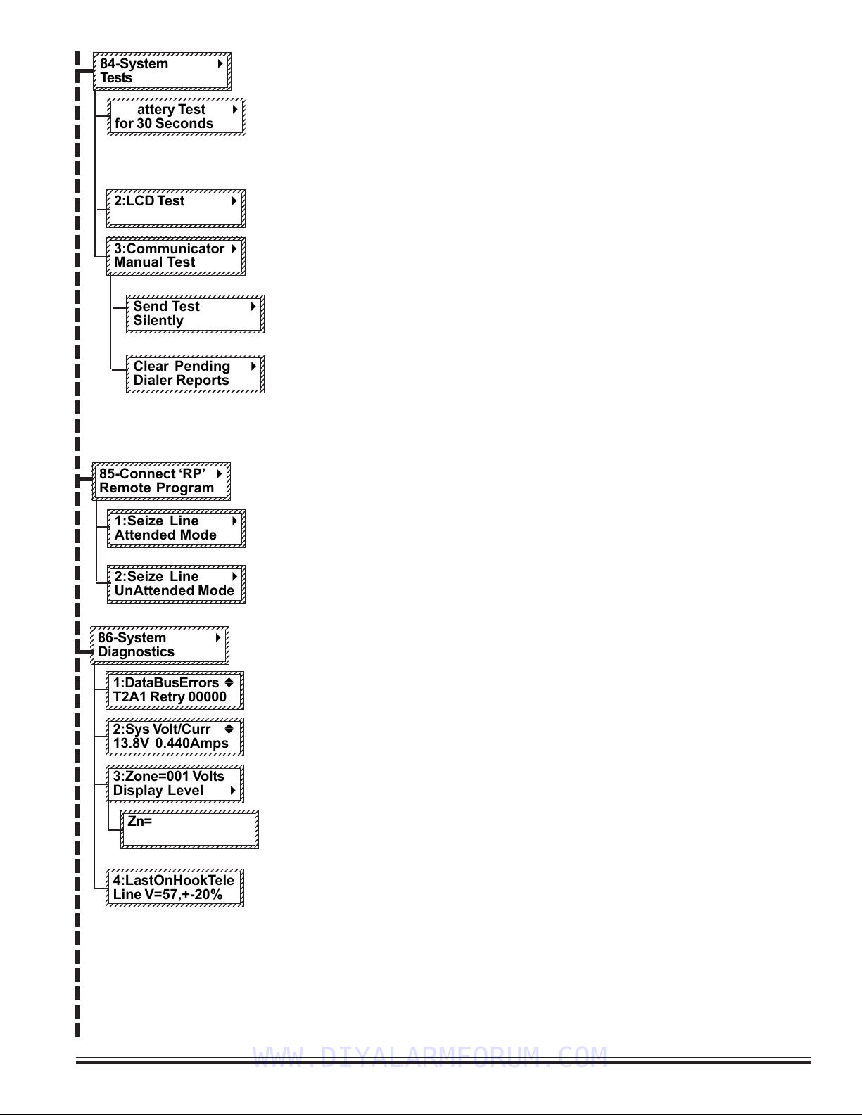
M1EZ8 Installation and Programming Page 17
[Effective w/Firmware 4.3.6]
To perform system tests press the right arrow key. Then press the up or down arrow keys to
select one of the three tests.
The control’s standby battery is load tested automatically every 24hrs. However, it can also be
manually load tested anytime using this option. Press the right arrow key to start the test. The
battery is placed under load for 30 seconds and the battery voltage and system current is
displayed. If the battery falls below a set level, a Low Battery trouble will occur. If it’s necessary
to replace the battery, this test should be used to test and clear a Low Battery Trouble condition.
To test the keypad’s LCD screen press the RIGHT arrow key. The entire screen should appear
black indicating all pixels are working. To exit press the * key.
To manually test the communicator (dialer) press the RIGHT arrow key. Testing is done using
the first phone number that is programmed to send a test code. If there is no phone number
programmed to send a test code, the test will end. To exit this menu press the * key.
There are two types of test, silent and monitored. To silently send a test press the right
arrow key from this display. To hear the test using the inside speakers (OUT1) press the up
or down arrow key to bring up the following display.
This special option allows any pending (not reported) dialer communications to be cleared
or cancelled. Typically this will be used only for initial installation and testing.
NOTE: ALWAYS NOTIFY THE MONITORING STATION BEFORE TESTING THE DIALER! If the test
should fail, a Comm Fail trouble will occur. To clear a Comm Fail the dialer must be able to
complete a good communication.
To connect ELK’s Remote Program PC software (RP) via the user assisted method, press the
RIGHT arrow key and then select the connection mode with the UP or DOWN arrow keys.
1:Seize Line Attended Mode - 1) Allows RP connection to begin on an already established voice
connection between the control phone line and the RP Computer. 2) Also useful for manually
answering an incoming call from the RP Computer with programming Rings to Auto Answer.
2:Seize Line Unattended Mode - Pressing the RIGHT arrow key causes the control to dial the
programmed RP telephone number. The RP Computer must be in the “wait for call” mode.
This is a collection of tools for diagnosing system problems. Press the RIGHT arrow key and
enter a valid user code to begin. Press the UP or DOWN keys to select one of the four tools:
This tool is useful for determining if data bus errors are accumulating. It displays the device
type and number of retries accumulated since the last power-up.
This tool displays the control’s voltage and the average current being drawn from the power
supply.
This tool allows the voltage on each zone to be displayed in real time. It changes as contacts
or devices are violated. Press the RIGHT arrow key to begin.
Use the UP or DOWN keys to scroll through each zone. The displayed information consists of:
the present zone voltage, the L low and H high alarm thresholds, and the analog (A to D)
equivalent of the zone voltage..
This is a read only screen displaying the telephone line voltage during the last on-hook
condition. It is an approximate measurement accurate to only +-20%.
123456789012345678901234567890
1
2345678901234567890123456789
0
1
2345678901234567890123456789
0
1
2345678901234567890123456789
0
1
2345678901234567890123456789
0
1
2345678901234567890123456789
0
1
2345678901234567890123456789
0
1
2345678901234567890123456789
0
123456789012345678901234567890
85-Connect ‘RP’ r
Remote Program
123456789012345678901234567890
1
2345678901234567890123456789
0
1
2345678901234567890123456789
0
1
2345678901234567890123456789
0
1
2345678901234567890123456789
0
1
2345678901234567890123456789
0
1
2345678901234567890123456789
0
1
2345678901234567890123456789
0
123456789012345678901234567890
2:LCD Test r
123456789012345678901234567890
1
2345678901234567890123456789
0
1
2345678901234567890123456789
0
1
2345678901234567890123456789
0
1
2345678901234567890123456789
0
1
2345678901234567890123456789
0
1
2345678901234567890123456789
0
1
2345678901234567890123456789
0
123456789012345678901234567890
3:Communicator r
Manual Test
123456789012345678901234567890
1
2345678901234567890123456789
0
1
2345678901234567890123456789
0
1
2345678901234567890123456789
0
1
2345678901234567890123456789
0
1
2345678901234567890123456789
0
1
2345678901234567890123456789
0
1
2345678901234567890123456789
0
123456789012345678901234567890
1:Seize Line r
Attended Mode
123456789012345678901234567890
1
2345678901234567890123456789
0
1
2345678901234567890123456789
0
1
2345678901234567890123456789
0
1
2345678901234567890123456789
0
1
2345678901234567890123456789
0
1
2345678901234567890123456789
0
1
2345678901234567890123456789
0
123456789012345678901234567890
2:Seize Line r
UnAttended Mode
123456789012345678901234567890
1
2345678901234567890123456789
0
1
2345678901234567890123456789
0
1
2345678901234567890123456789
0
1
2345678901234567890123456789
0
1
2345678901234567890123456789
0
1
2345678901234567890123456789
0
1
2345678901234567890123456789
0
123456789012345678901234567890
86-System r
Diagnostics
123456789012345678901234567890
1
2345678901234567890123456789
0
1
2345678901234567890123456789
0
1
2345678901234567890123456789
0
1
2345678901234567890123456789
0
1
2345678901234567890123456789
0
1
2345678901234567890123456789
0
1
2345678901234567890123456789
0
123456789012345678901234567890
1:DataBusErrors b
T2A1 Retry 00000
123456789012345678901234567890
1
2345678901234567890123456789
0
1
2345678901234567890123456789
0
1
2345678901234567890123456789
0
1
2345678901234567890123456789
0
1
2345678901234567890123456789
0
1
2345678901234567890123456789
0
1
2345678901234567890123456789
0
123456789012345678901234567890
2:Sys Volt/Curr b
13.8V 0.440Amps
123456789012345678901234567890
1
2345678901234567890123456789
0
1
2345678901234567890123456789
0
1
2345678901234567890123456789
0
1
2345678901234567890123456789
0
1
2345678901234567890123456789
0
1
2345678901234567890123456789
0
1
2345678901234567890123456789
0
123456789012345678901234567890
3:Zone=001 Volts
Display Level r
123456789012345678901234567890
1
2345678901234567890123456789
0
1
2345678901234567890123456789
0
1
2345678901234567890123456789
0
1
2345678901234567890123456789
0
1
2345678901234567890123456789
0
1
2345678901234567890123456789
0
1
2345678901234567890123456789
0
123456789012345678901234567890
4:LastOnHookTele
Line V=57,+-20%
123456789012345678901234567890
1
2345678901234567890123456789
0
1
2345678901234567890123456789
0
1
2345678901234567890123456789
0
1
2345678901234567890123456789
0
1
2345678901234567890123456789
0
1
2345678901234567890123456789
0
1
2345678901234567890123456789
0
123456789012345678901234567890
Zn=001 Volt=07.2
L04.6 H09.0 A132
123456789012345678901234567890
1
2345678901234567890123456789
0
1
2345678901234567890123456789
0
1
2345678901234567890123456789
0
1
2345678901234567890123456789
0
1
2345678901234567890123456789
0
1
2345678901234567890123456789
0
1
2345678901234567890123456789
0
1
2345678901234567890123456789
0
123456789012345678901234567890
1:Battery Test r
for 30 Seconds
123456789012345678901234567890
1
2345678901234567890123456789
0
1
2345678901234567890123456789
0
1
2345678901234567890123456789
0
1
2345678901234567890123456789
0
1
2345678901234567890123456789
0
1
2345678901234567890123456789
0
1
2345678901234567890123456789
0
123456789012345678901234567890
84-System r
Tests
123456789012345678901234567890
1
2345678901234567890123456789
0
1
2345678901234567890123456789
0
1
2345678901234567890123456789
0
1
2345678901234567890123456789
0
1
2345678901234567890123456789
0
1
2345678901234567890123456789
0
1
2345678901234567890123456789
0
123456789012345678901234567890
Send Test r
Silently
123456789012345678901234567890
1
2345678901234567890123456789
0
1
2345678901234567890123456789
0
1
2345678901234567890123456789
0
1
2345678901234567890123456789
0
1
2345678901234567890123456789
0
1
2345678901234567890123456789
0
1
2345678901234567890123456789
0
123456789012345678901234567890
Clear Pending r
Dialer Reports
WWW.DIYALARMFORUM.COM

M1EZ8 Installation and Programming
Page 18 [Effective w/Firmware 4.3.6]
123456789012345678901234567890
1
2345678901234567890123456789
0
1
2345678901234567890123456789
0
1
2345678901234567890123456789
0
1
2345678901234567890123456789
0
1
2345678901234567890123456789
0
1
2345678901234567890123456789
0
1
2345678901234567890123456789
0
123456789012345678901234567890
9-Installation r
Programming (0)
Requires
Installer
Code
From this menu you may press the RIGHT arrow to enter Installation Level Programming. If
the Installer Programming Code has not already been entered it will be required at this
time. REFER TO PAGE 20 FOR PROGRAMMING INSTRUCTIONS
Menu 0 - Select Keypad Alternate Area - Multi-area (Partition) Operation
Press the RIGHT arrow key to select this menu and display the following:
Enter a valid user code. The control does not allow (restricts) mapping or viewing of
areas that are not authorized for the user code.
MAPPING TO AN INDIVIDUAL AREA
Enter an area number from 1 to 8 OR scroll UP and DOWN with the arrow keys.
Press the Right Arrow key to map the Keypad to the area shown. The LCD display and
the Ready / Armed LEDs will show the status for the mapped area for 1 minute. During
this minute, it is possible to arm, disarm, bypass, etc. the mapped area from this
keypad. Each time a key is pressed the 1 minute is restarted. However, after 1 minute
of no keypress activity, the keypad will return to its original primary assigned area.
ACCESSING ACONSOLIDATED DISPLAYOF ALL VALID AREAS
Entering “0” for the area number immediately maps the Keypad to a consolidated
‘snapshot’ of all authorized areas. This permits quick arming and disarming only. If an
area is not ready to arm it will be necessary to map individually to that area to view the
violated zone(s) and either secure or bypass them prior to arming.
This example shows all 8 areas, meaning that the User Code was valid for all 8.
The display only shows the areas for which the user code is authorized.
Note the letter beneath each area number.
This menu allows the keypad to be mapped temporarily to any other area, allowing multi-area (partitioned) opera-
tion. An individually mapped area can be armed, disarmed, and controlled just as if the keypad were permanently
assigned to that area. It may also be used to access a consolidated display of all areas at once, showing the
status of each area.
To reach the keypad menus press the center navigation key labeled “ELK”. A user code may be required depend-
ing on how the control is programmed. The four arrow keys around the Elk key are used to scroll, backup, etc.
Pressing the RIGHT arrow key will select the displayed menu.
1. Press the ELK key. Enter a user code if prompted.
2. Use the UP or DOWN arrow keys to find menu “0-Select Keypad Alternate Area”.
1234567890123456789012345678
1
23456789012345678901234567
8
1
23456789012345678901234567
8
1
23456789012345678901234567
8
1
23456789012345678901234567
8
1
23456789012345678901234567
8
1
23456789012345678901234567
8
1
23456789012345678901234567
8
1
23456789012345678901234567
8
1234567890123456789012345678
0-Select Keypad
Alternate Area r
1234567890123456789012345678
1
23456789012345678901234567
8
1
23456789012345678901234567
8
1
23456789012345678901234567
8
1
23456789012345678901234567
8
1
23456789012345678901234567
8
1
23456789012345678901234567
8
1
23456789012345678901234567
8
1
23456789012345678901234567
8
1234567890123456789012345678
Auth. Required
Enter Valid PIN
123456789012345678901234567890
1
2345678901234567890123456789
0
1
2345678901234567890123456789
0
1
2345678901234567890123456789
0
1
2345678901234567890123456789
0
1
2345678901234567890123456789
0
1
2345678901234567890123456789
0
1
2345678901234567890123456789
0
1
2345678901234567890123456789
0
123456789012345678901234567890
ChangeKPArea-1
r
[Area Name] A1
The single upper case “X” indicates the primary area. This area is controlled exclusively from
the regular operation screens.
A lower case “r” below an area indicates the area is Ready to Arm.
A lower case “n” below an area indicates the area is Not Ready.
A upper case “A” below an area indicates the area is Armed.
This example shows the user code was only authorized for areas 1, 2, and 3. The
unauthorized area(s) have a “-” below them.
To change or ‘toggle’ the arm status of an area, press the number key representing
the area number. IMPORTANT: The area status is not “real time”. It is a snapshot
taken when the RIGHT arrow key was pressed. If a zone has since become violated
the area will still be displaying “r”, however the letter will immediately change to “n”
and the keypad will emit an error tone when an attempt is made to arm by pressing
the area number.
When finished, press the “*” key to exit.
123456789012345678901234567890
1
2345678901234567890123456789
0
1
2345678901234567890123456789
0
1
2345678901234567890123456789
0
1
2345678901234567890123456789
0
1
2345678901234567890123456789
0
1
2345678901234567890123456789
0
1
2345678901234567890123456789
0
1
2345678901234567890123456789
0
123456789012345678901234567890
ChangeKPArea-0 r
0=All Areas
12345678901234567890123456789
1
234567890123456789012345678
9
1
234567890123456789012345678
9
1
234567890123456789012345678
9
1
234567890123456789012345678
9
1
234567890123456789012345678
9
1
234567890123456789012345678
9
1
234567890123456789012345678
9
1
234567890123456789012345678
9
12345678901234567890123456789
Area# 12345678
Status X r r r r r r r
12345678901234567890123456789012
1
234567890123456789012345678901
2
1
234567890123456789012345678901
2
1
234567890123456789012345678901
2
1
234567890123456789012345678901
2
1
234567890123456789012345678901
2
1
234567890123456789012345678901
2
1
234567890123456789012345678901
2
1
234567890123456789012345678901
2
12345678901234567890123456789012
Area# 12345678
Status X r r - - - - - r
NOTE: The ElkRP software can be used to lockout certain local program capabilities for “anti-takeover” purposes. The
number in the lower right corner of this menu will indicate the level of lockout as follows: (0) = No lockout, (1)=Lockout
Telephone number programming - view everything, (2)=Lockout ALL programming - view everything, (3)=Lockout ALL
Programming and Viewing. This can only be set or removed from the ELK-RP Remote Programming Software.
WWW.DIYALARMFORUM.COM

M1EZ8 Installation and Programming Page 19
[Effective w/Firmware 4.3.6]
3.1 Introduction
The Security functionality of the Control can be programmed either from an ELK-M1KP LCD Keypad OR from the ELK-RP PC
Software. The keypad features a menu-driven “Text” based interface with simple Yes/No answers for most options. After just
a short amount of experience the average installer will not even require an instruction manual to keypad program the control.
For the Automation functionality the ELK-RP PC Software is a requirement. The options and capabilities available for
automation are so unique and powerful that it takes a PC to make use of all the benefits. The control features a powerful
“Whenever/And/Then” RULES based programming that allows almost any imaginable operation.
3.2 Local Keypad Programming
There are two levels of operation for programming the control locally, user level and installer level.
- User level programming provides the ability to add, change, or delete user passcodes and names. It also allows custom
automation settings to be viewed and changed. A master user code is required to access the user code and custom settings
screens. User programming is explained in the User’s Guide.
- Installer level programming allows total customizing of the Security operating features. Only the installer code may access
this level. If the installer code is lost or forgotten, it is impossible to program the control locally. Anyone attempting installer
level programming should be familiar with the contents of this publication prior to programming the control panel. If remote
programming is used, it is possible to “lock out” or prevent takeover of a control by another installation company by selecting
“Lockout Local Prog.” This prevents the installer passcode from gaining access to programming via an LCD keypad. The
installer passcode may still be used for the non-programming functions described in Chapter 2. Lockout Local Prog does not
affect remote programming.
3.3 Local or Remote Computer Programming (ELK-RP) and Anti-Takeover
ELK-RP programming utilizes extensive error checking and security safeguards, including data encryption, password log-on,
serial number, and dealer assigned RP access code. The serial # identifies the control to RP while the RP access code
identifies the computer to the control prior to a programming session. RP loads the access code during the first connection. It
cannot be viewed or changed from local keypad programming. In addition to these safeguards, you can set an anti-takeover
option from RP which prevents certain keypad programming. Even a total default of the panel programming cannot reset the
anti-takeover option once it is set..
The Factory Default Elk-RP Access Code is: 2 4 6 8 0 1
3.4 Area Partitioning
The control may be divided into 1 to 8 independent areas (partitions). Each area appears as a full-featured system, allowing
one control to be shared by multiple, independent departments within a common structure. Zones, User Codes, and
Keypads may be assigned to any 1 area up to the maximum number available. An example is a single business divided into
separate departments, each department occupied by different employees. Mount the control in a secure area (common utility
closet) with dedicated and uninterrupted AC power and telephone service. Then assign zones, codes, and keypads to each
department.
The Alarm Output (Output 2) activates on all alarms, regardless of the area. The RP Software Rules can be used create
additional (separate) outputs. When reporting to the central station events like AC Power Failure, Automatic tests, Low Battery,
etc., are considered system reports and are transmitted using the Area 1 account number. If area partitioning is not desired,
simply designate all zones to a single area (Area 1) which is the factory default setting for zones 1-8.
COMMON AREA - Another popular feature is the ability to have one or more areas made “common” to Area 1. This is often
referred to as a “Vestibule Feature”. Any of the Areas 2 thru 8 may be made common to Area 1. The result is: Area 1 cannot be
armed until all its common areas are armed. Once armed, Area 1 will disarm if any common area becomes disarmed. This
is good for lobbies or vestibules shared by two or more businesses. Each business must have their own area keypad.
NOTE: If you want Area 1 to automatically arm when all its common areas become armed, use a Whenever/And/Then rule
from the RP software to do this.
Section 3 - Programming The Control
WWW.DIYALARMFORUM.COM

M1EZ8 Installation and Programming
Page 20 [Effective w/Firmware 4.3.6]
3.5 Communicator Setup Checklist
The Communicator (Dialer) can dial up to 8 telephone numbers in addition to the RP computer. Digital reporting formats
include: Pulse 4+2, SIA, Contact ID, and Pager. Use the following checklist for each required telephone number.
1. Under Menu 08 - Telephone Account Setup, select one of the telephone numbers and program the following:
Option 01: Select the desired reporting format - 0=Disable, 1=Contact ID, 2=SIA, 3=Pulse 4+2, 4=Pager.
Option 02: Set the priority for the first (primary number) to 0 = Always Report.
Option 03: Program the telephone number digits to be dialed. No special start or ending characters are required.
Option 04: Set the dial attempts to greater than 0. For Digital reports 8 is suggested.
Option 05 Program the digits for the account number to report. Each area (partition) has its own Acct. Number.
Option 13: Select Yes to have Area info, Zone Alarms, Zone Restores, and Zone Unbypasses reported to this Tel #.
Option 14: Select Yes if you wish to have Zone Bypasses reported to this Tel #.
Option 15: Select Yes if you wish to have Zone Troubles reported to this Tel #.
Option 16: Select Yes if you wish to have User (Open/Close) Reports reported to this Tel #.
Option 17: Select Yes if you wish to have Global System Events (AC Fail, Low Battery, etc.) reported to this Tel #.
Option 18: Although not required, you may program a text name for each telephone number.
2. Under Menu 09 - Area Reporting Codes, select the area (partition) and program the desired options such as: Dialer
Delay, Alarm Abort, Auto Open/Closings, etc. then .
3. Under Menu 10 - Zone Reporting Codes, select the zone number and program the desired options such as: Zone Alarms,
Restores, Bypasses, or Trouble.
Option A: For Zone Alarm program a two digit code. To have the automatic SIA or Contact ID report codes transmitted
simply program a nonzero value. I.E. Program a 1 (01).
Option R: For Zone Restore program a two digit code. For automatic SIA or Contact ID codes program a 1 (01).
Option B: For Zone Bypass program a two digit code. For automatic SIA or Contact ID codes program a 1 (01).
Option T: For Zone Trouble program a two digit code. For automatic SIA or Contact ID codes program a 1 (01).
4. Under Menu 11 - F Key Reporting Codes, select and program the alarm code for each desired Keypad Panic Key. NOTE:
Keypad Panics only have Alarm report codes, they do not have restore codes. For automatic SIA or Contact ID codes
program a 1 (01).
5. Under Menu 12 - Sys Report Code Options & Codes, select and program each desired option such as: AC Fail, Low
Battery, Automatic Test, and other system wide options, including the time values for certain options. For automatic SIA or
Contact ID report codes program a 1 (01).
6. Under Menu 13 - User Report Codes, select and and program an Open or Close report code for any User(s) that you
wish to track arm/disarm events, including arm/disarm by the Installer Code or Elk-RP computer.
3.6 Entering Installer Level Programming
1. Press the center ‘ELK’ key once followed by the DOWN arrow key until display reads “9-Installation Programming”. NOTE:
The keypad may beep and display the following:
2. Enter the Installer Program Code when required.
Press the right arrow key to select the “Installation Programming” option.
The Factory Default Installer Program Code is: 1 7 2 8 3 9
For security against unauthorized programming changes, the installer code should be changed from its factory default setting.
This can be done from Menu 07 - Globals System Definitions, Option 42.
Once the Installer Code has been entered, the first programming menu will display and a 4 minute timer will be started.
If there is no key-press activity during this time period the control will automatically exit from the programming mode. It
is easy to navigate around and between the programming menus and options using the up and down arrow keys. When
the correct menu or option is located, press the right arrow key to proceed into that menu.
Refer to the Quick Reference Guide on the following page to locate a particular menu or to see what options
appear under each menu. Refer to the individual menus and their option descriptions for details about each of the
programmable items.
123456789012345678901234567890121234
1
2345678901234567890123456789012123
4
1
2345678901234567890123456789012123
4
1
2345678901234567890123456789012123
4
1
2345678901234567890123456789012123
4
1
2345678901234567890123456789012123
4
1
2345678901234567890123456789012123
4
1
2345678901234567890123456789012123
4
1
2345678901234567890123456789012123
4
1
2345678901234567890123456789012123
4
123456789012345678901234567890121234
Auth. Required
Enter Valid Pin
WWW.DIYALARMFORUM.COM
This manual suits for next models
3
Table of contents
Popular Control System manuals by other brands

Siemens
Siemens SINUMERIK 828D Turning Connection instructions

Redarc
Redarc MANAGER 30 user guide

Triangle MicroSystems
Triangle MicroSystems PETROSMART EZ installation instructions

Controls
Controls KS-105 product manual

Rise
Rise RANGER 500/I installation manual

NEC
NEC ElectraElite 48 System hardware manual


Rockwell Automation
Rockwell Automation Allen-Bradley ControlLogix SIL 2 Reference manual

Pilz
Pilz PMCprimo MC operating manual

Norac
Norac UC7 installation manual

Homa
Homa PCM Series Original instruction manual

FCS
FCS Sentinel 2 user guide

Rockwell Automation
Rockwell Automation CENTERLINE 2100 instruction manual