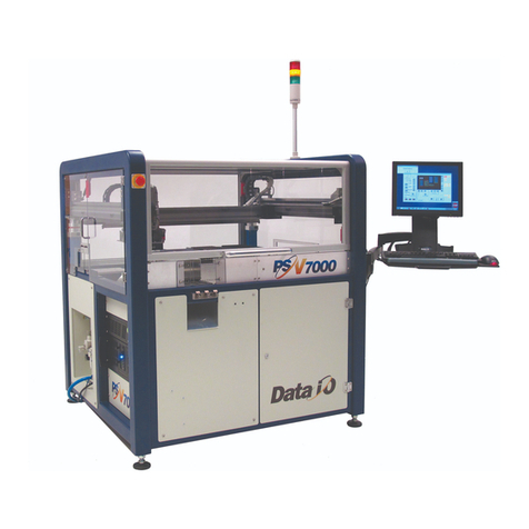
Data I/O PSV5000 User manual

Operator’s Manual
Automated Programming and Handling
096-0466-001E
Now available
with
LumenX Programmers

ii Data I/O • 096-0466-001E
096-0466-001 January 2019
Data I/O has endeavored to ensure that the information in this document is accurate and complete. Data I/O assumes no
liability for errors, or for any incidental, consequential, indirect, or special damages, including, without limitation, loss of
use, loss or alteration of data, delays, or lost profits or savings, arising from the use of this document or the applicable Data
I/O product.
Any algorithms, adapters or other Data I/O products provided or sold by Data I/O to you must first be tested and verified
by you for use in your application prior to use in a production environment. Data I/O does not warrant that the Data I/O
products will meet your requirements or that operation of the Data I/O products will be uninterrupted or error-free.
No part of this document may be reproduced or transmitted in any form or by any means, electronic or mechanical, for any
purpose, without written permission from Data I/O Corporation.
Data I/O, TaskLink, PSV5000, and Lumen[X] are trademarks of Data I/O Corporation.
Data I/O Corporation acknowledges the trademarks of other organizations for their respective products or services men-
tioned in this document.
© 2014–2019 Data I/O Corporation
All rights reserved

page i
Contents —Operator’s Manual
PSV5000 Machine Components 1
Work Surface Components 2
Power Panel Components 3
Programmer Overview 3
SAFETY MESSAGES AND PRECAUTIONS 7
Warnings and Cautions 7
Safety Systems 9
Emergency Stop (E-Stop) Buttons 9
Safety Doors and Interlocks 10
Electrostatic Discharge 10
RUNNING A JOB ON PSV5000 13
Requirements 13
List of Steps to Start a Job 13
1>> Checking the System 14
2>> Installing Input/Output Media 14
Setting Up Device Trays and Reject Bin 15
Installing the Tape-In Module Option 18
Installing the Tape Rewind Module 21
Checking the Tape Output Option 23
3>> Socket Adapters and Actuator Plates 31
Finding Socket Adapter Part Numbers 31
Installing Adapters and Actuators on FlashCORE 32
Adjusting the Actuator Plates 35
Installing Adapters and Actuators on LumenX 35
4>> Identifying the Correct Probes 38
Removing and Installing the Probe 40
Removing the Probe Holder 42
How to Teach a new TOOL Position 43
5>> Installing the Correct Laser Shuttle Tips 44

ii Data I/O • 096-0466-001E
6>> Running the Automatic Tray Feeder 45
Power Up the Tray Feeder 46
Verify Tray Feeder Initialization 46
Teaching the Tray 1 Location 48
7>> Turning PSV5000 System Power ON 51
8>> Selecting a Job—Starting CH700 51
To select and start a job for FlashCORE Programmers 52
To select and start a job for LumenX Programmers 54
9>> (Optional) Preselecting Programmers 56
10>> Setting Media and Options—the Setup Window 57
Verifying Media Setup 59
11>> Starting Programming 61
Laser Marking 61
Removing Devices 64
Stopping the System 64
Emergency Stop 65
Pausing a Job 66
Ending a Job 67
LIGHT TOWER INTERPRETATION 68
CHANGING PROGRAMMER STATUS 70
Disabling Programmers 70
MY JOBS THAT USE THE SAME SETUP 72
FINISHING A JOB 74
Turning PSV5000 System Power OFF 74
BASIC TRAY FEEDER OPERATION 76
IF YOU HAVE TROUBLE 77
INDEX 79
TECHNICAL SUPPORT
83

■ Work Surface Components ≡ Programmer Overview
PSV5000 Operator’s Manual - 1 -
PSV5000 Machine Components
This Visual Index of PSV5000 locates features and subassemblies on the machine.
Figure 1: Features of PSV5000; front (top) and back (bottom)
Gantry
Work surface
Optional:
Tape Output
Monitor and
Keyboard
Support for
Tape Feeder
Support for Option-
al Tray Feeder.
Light Tower
Interlocked
Safety Doors
Accessory
Drawer
Power Panel
E-Stop
Optional:
Laser Control
E-Stop
ESD ground
connection

PSV5000 Machine Components ■Work Surface Components
- 2 - Data I/O ■096-0466-001E
Work Surface Components
Figure 2: Some features on the PSV5000 work surface. The system can be
configured with a reject tray or a reject bin. Note that the static trays and
Tray Feeder would not both be used at the same time. (Refer to Owner’s
Manual or on-screen Help).
Tray alignment pins (3)
Tray Feeder
(optional)
Tape-In Module
[Tape Feeder] (optional)
Programmers
(only FC shown here)
Tray-capture
Magnet
Static Tray
Reject Bin
Tape-Out Module
(optional)
Vision

■ Power Panel Components ≡ Programmer Overview
PSV5000 Operator’s Manual - 3 -
Power Panel Components
Figure 3: Rear View of PSV5000. For information on connecting the facili-
ties, see the Owner’s Manual.
Programmer Overview
Two programmer models are available for the PSV5000: both models can be in-
stalled next to each other, but programming jobs can only be set to use one model.
Main Pressure Regulator
AC power connection
Main Power Switch;
Shown here in OFF position
(with lockout)
Air inlet valve
(with lockout
Internet connection
Programmer Power only
Socket Opener Pressure
Regulator
Main air inlet
Air Filter

PSV5000 Machine Components ■Power Panel Components
- 4 - Data I/O ■096-0466-001E
LumenX
Lumen™X is Data I/O’s latest programmer at the time of this document.
Each LumenX programmer requires one to two Actuator Plates and one to
eight Socket Adapters for the specific device package being programmed.
Each Socket Adapter has one socket.
Figure 4: One LumenX programmer with eight Sockets held down by four
clamps actuated by two adjustable Actuator Plates. Orange arrows indicate
Socket Adapters for the front half of the programmer.
LED Interpretation on LumenX Programmers
Figure 5: Each LumenX Socket Adapter has four LEDs and indicates
PIN 1 as shown. All four LEDs light at once only during startup and go off
when the startup procedure is complete.The Actuator Plate is not shown
here for clarity.
Green = PASS PROGRAMMING
Yellow = BUSY
Red = FAILED PROGRAMMING
White = CONTINUITY ERROR
Actuator Plate (2)
Clamp (4)
Spring Clip
(1 per clamp)

■ Power Panel Components ≡ Programmer Overview
PSV5000 Operator’s Manual - 5 -
FlashCORE III
Each FlashCORE III programmer requires an Actuator Plate and a Socket
Adapter for the specific device package being programmed. Each Socket
Adapter typically has four sockets.
Figure 6: FlashCORE III programmers on PSV5000.
LED Interpretation on FlashCORE Programmers
Figure 7: Each FlashCORE Socket Adapter has one red LED per socket. A)
Standard Adapter; socket 2 has failed. B) HIC Adapter. Socket 3 has failed.
The Actuator Plate is not shown on the HIC Adapter for clarity.
Supported Integrated Circuits (Devices)
• Flash Memory:
NOR, NAND, MCP, MMC, e.MMC, SD, MoviNAND, OneNAND, iNAND,
Serial Flash, EEPROM, EPROM
• Microcontrollers
• Logic devices:
CPLDs, FPGAs, PLDs
Actuator Plate
Socket Adapter
Programmer

PSV5000 Machine Components ■Power Panel Components
- 6 - Data I/O ■096-0466-001E
For administrative
functions and more, see
the PSV5000 Owner’s
Manual is in the
C:\CH700 directory on
the Handler computer
and also available on
our Technical Library on
our website).
Operator’s Manual
Operation
This manual includes basic operation of the PSV5000 System,
but not functions deemed Administrator functions such as
creating a job, teaching Package Files, or creating a data file
from a master device.
PSV5000 is a programming and handling system for traditional and fine-pitched
integrated circuits (devices). It accepts most package types. The on-screen applica-
tion that runs PSV5000 is CH700.
Operator functions include installing some hardware, checking hardware setup,
turning on power, starting TaskLink, loading a job, and running a job. Operators
generally follow this sequence to process devices:
Figure 1: Operator Functions. For a list of these steps, see page 13.
Safety
Precautions
page 7
Install media,
check options
page 14
Install Socket
Adapters,
page 32
Check probe
tips / shuttle
tips,
page 38
PSV5000
power up,
page 51
Start Task-
Link/LumenX,
load job,
page 52
Set UI media
and options,
page 57
Ensure
Package File
was taught
Start Pro-
gramming,
page 61
Finishing...
Finish or stop
a Job,
page 64 and
74
Resolving
Basic Errors,
page 68

■ Warnings and Cautions ≡ Programmer Overview
PSV5000 Operator’s Manual - 7 -
Definition of a
Warning->
Definition of a
Caution–>
Safety Messages and Precautions
For your safety and preventing lost time and damage to equipment, this
manual uses special symbols, paragraphs, and color to call your attention to
hazardous situations and recommends safe practices to help avoid them.
Please read and heed the warning messages. They look like the ones below.
Warnings and Cautions
Special paragraphs with red lines are safety warnings as follows:
WARNING: This is a warning message!
It has red text and calls your attention to potentially hazardous
situations and practices that might injure people or cause serious
monetary loss.
CAUTION:
This is a caution message!
It calls your attention to potentially hazardous situations and practices
that might damage equipment.
(The potential loss is not as serious as a warning.)

Safety Messages and Precautions ■Safety Symbols
- 8 - Data I/O ■096-0466-001E
Safety Symbols
This manual uses the following Safety symbols:
—Crush Point (Pinch Point) Warning
—Crush (punto de pellizco) ADVERTENCIA
—Crush (Prise Punkt) Warnung
—Electric Shock Warning
—ADVERTENCIA de descarga eléctrica
—Elektroschock Warnung
—General Hazard Warning
—ADVERTENCIA de peligro general
—General Hazard Warning
—Noise Warning; may be over 80 db
—ADVERTENCIA de ruido; puede ser más de 80 decibeles
—Lärm-Warnung; möglicherweise mehr als 80 Dezibel
—Eye Hazard Warning
—ADVERTENCIA de peligro del ojo
—Auge Hazard Warning
—Collision Warning
—ADVERTENCIA de colisión
—Collision Warning
—Laser Hazard Warning
—ADVERTENCIA de peligro del laser
—Laser-Hazard Warning
—Compressed Air Warning
—ADVERTENCIA de aire comprimido
—Druckluft-Warnung
—Electrostatic Discharge Warning (ESD)
—ADVERTENCIA de descarga electrostática
—Elektrostatische Entladung Warnung

■ Safety Systems ≡ Emergency Stop (E-Stop) Buttons
PSV5000 Operator’s Manual - 9 -
If you have a Laser
marker, the E-Stop on
the front control panel
only stops the laser.
Safety Systems
The PSV5000 System has several safety systems to prevent personal injury
and system damage. These systems include E-Stops and safety doors. If your
system has a Laser Module, it comes with a fume extractor.
Emergency Stop (E-Stop) Buttons
Two large, red Emergency Stop buttons are located near the top of the
PSV5000 System—one on the left side near the front and one on the right
side near back of the machine. When an E-Stop button is pressed, the gantry
stops moving immediately. See the warning below.
To recover from an emergency stop, see To Restart the System on page 65.
Figure 2: There are two Emergency Stop (E-Stop) buttons: on left near
front, and on right near back of the machine.
WARNING: Shock hazard! Pressing an E-Stop button removes
power from the motion controller (gantry) only, and stops
communication to the Laser Marking head. It does NOT remove
electrical power from the PSV5000 or any optional equipment
installed. Turn the main power OFF before opening any access doors.
WARNING: Pinch hazard! The E-Stop does not shut off air.
Socket actuators can still move down and up.

Safety Messages and Precautions ■Safety Systems
- 10 - Data I/O ■096-0466-001E
Park Position:
Where the head
stops when a job
is paused or
ended; near the
side at center.
Tool Position:
Near front center
for easy access to
the PNP head.
Home Position:
Right rear;
automatic
initialization when
a job is started.
Safety Doors and Interlocks
During operation, when the high-speed PNP head is processing devices, the clear
plastic safety doors around the workspace are closed to protect operators from in-
jury. Each safety door has a safety interlock which stops gantry movement if the
operator forgets to first park the PNP head. See next heading.
Prior to opening a safety door
Normally, if the power is ON, before opening any safety door:
• at the Run window, a job should be either Paused or Finished
(stopped), or
• at the Gantry window, the PNP head should be sent to the park or tool
position (by clicking Park or Tool label), or
• at the Setup window, any time before a job is started.
WARNING: Possible collision hazard! The high speed and force
of the gantry can seriously harm anyone working inside the workspace.
When working in the machine workspace, moving the PNP head must
be the responsibility of only one qualified individual. All others must
stay clear of the machine controls to prevent injury to that person.
Never bypass or otherwise render safety interlocks inoperable.
WARNING: Shock hazard! Opening the safety doors stops
motion of the gantry only. It does not remove electrical power from
the machine or any optional equipment.
Turn the main power OFF for safety unless otherwise directed.
Electrostatic Discharge
Devices (integrated circuits) are very sensitive to static, and could be damaged by
unintended electrostatic discharge while being handled. So ensure a common elec-
tric potential (ground) exists between a static-sensitive device or component, its
environment, and the operator.
Operators should wear an antistatic wrist strap (Data I/O part number
440-0021-001+) connected to one of the grounding connections on the machine.
The wrist strap should contain a 1–10 M-ohm current limiting resistor.

■ Safety Systems ≡ Electrostatic Discharge
PSV5000 Operator’s Manual - 11 -
Handling Devices Safely
To prevent damage to device pins, use a vacuum tool/tweezer to pick up devices.
The vacuum tool is designed to handle devices without damaging them.
CAUTION:
Possible device pin damage! Do not touch devices
with your hands or any implement other than the vacuum tool. Doing
so could damage devices with fine-pitched leads.
Vacuum tools use a squeezable air bladder for suction. There are a variety of mod-
els, sizes and tips. Some tips are replaceable.
Figure 3: A Vacuum Tweezer: Data I/O PN 565-8000.

Safety Messages and Precautions ■General Precautions
- 12 - Data I/O ■096-0466-001E
General Precautions
To avoid possible personal injury or damage to the equipment, please ob-
serve the following practices:
• Only trained personnel should install, maintain, repair, or trou-
bleshoot this system.
• Do not operate the system unless you have been thoroughly trained,
and have read and understand the instructions in this manual,
particularly those that describe the system’s safety features.
• Do not operate the system if the safety shield doors or access doors
are not in their normal operating positions (unless you are a Data I/O
trained technician and are explicitly directed to do so by instructions
in this manual).
• Do not operate while servicing, replacing, or adjusting any compo-
nent unless directed to do so in this manual. Make sure that the
machine is properly shut down before working on PSV5000.
• Do not place any part of your body into the direct path of moving
parts.
• Do not disable or attempt to defeat any of the protective safety fea-
tures of this system. Personal injury or equipment damage can occur
if any safety systems are disabled. If you suspect that a safety feature
is damaged or malfunctioning, stop using the machine immediately
and contact Data I/O Customer Service or a local Data I/O approved
service representative.
• Use extra caution when working within the work surface. Open
safety doors do NOT cut power to all systems. Actuators can still
operate.
• Wearing hearing protection is recommended while operating the
machine if sound pressure levels exceed 85 decibels. Sound levels
may exceed 85 decibels depending on auxiliary equipment running
and your environment.
• Shut off the pressurized air or disconnect the air hose before ser-
vicing pneumatic parts.

■ Requirements ≡ Electrostatic Discharge
PSV5000 Operator’s Manual - 13 -
Running a Job on PSV5000
Requirements
Requirements prior to running a job on PSV5000:
• A task or job for your target device must already exist. This is gen-
erally an administrator function. Refer to TaskLink’s online Help or
Chapter 3 of the Owner’s Manual.
• You need to know the device and Socket Adapter for the target job, as
well as what input and output media is needed.
• Make sure all assemblies needed for the target job, such as the Single
Tray Feeder, a Marking System or the Tape Output System, are in-
stalled on the PSV5000 Machine. Refer to Chapter 2- Set Up of the
Owner’s Manual for more information.
Operators, please read Safety Systems on page 7 through page 12 (if you
have not already). You should generally be familiar with the
PSV5000 System.
List of Steps to Start a Job
Operator functions are in chronological order as follows:
1. Checking the System on page 14
2. Installing Input/Output Media on page 14
3. Socket Adapters and Actuator Plates on page 31
4. Installing the Correct Probes on page 38
5. Turning PSV5000 System Power ON on page 51
6. Selecting a Job and Starting CH700 on page 51
7. (Optional) Preselecting Programmers on page 56
8. Setting Media and Options—the Setup Window on page 57
The Package File should already have been taught. If not,
see the PSV5000 Owner’s Manual or your administrator.
9. (Optional) If an Automatic Tray Feeder is installed, see page 45.
10. (Optional) If Tape Output is installed, see page 23.
11. (Optional) If Laser Marking is employed, see page 44.
12. Starting Programming on page 61.
After Starting a Job...
•Stopping the System on page 64.
•Light Tower Interpretation on page 68.
•(Optional) Changing Programmer Status on page 70.
•Turning PSV5000 System Power OFF on page 74.
•(Optional) Operating the Single Tray Feeder on page 76.

Running a Job on PSV5000 ■List of Steps to Start a Job
- 14 - Data I/O ■096-0466-001E
Regardless of input
media used (trays or
tape), all should offer
devices right-side-up
(‘live bug’orientation.)
PSV5000 Machines
must be level and at
room temperature
before running a job.
1>> Checking the System
Before you set up for your job, check that:
• All side panels and doors are closed
• No one is working on the machine.
• The external air line is connected.
If the power and air pressure switches are already ON, the
pressure indicator number should be green.
2>> Installing Input/Output Media
Some optional equipment needs to be set up or their settings checked and
power turned ON, or a process started (even if the equipment was installed
by another individual, such as the administrator).
CAUTION:
Electrostatic discharge (ESD) hazard! Wear an ESD
strap or discharge static against a common ground to prevent damage
to Socket Adapters and devices.
CAUTION:
Safety hazard! Possible personal injury from moving
machinery. Always make sure that the PNP head is stopped in the Park
or Tool position before opening any access doors.
These input/output media are described in this section:
• Static Trays (next heading)
• Tape Feeder Input
• Tape Output
For the Tray Feeder input, see Setting Up an Automatic Tray Feeder in the
PSV5000 Owner’s Manual.
If your job or work process uses other options such as a Barcode Scanner,
make sure they are installed and ready. Check with your administrator or
see the PSV5000 Owner’s Manual.

■ List of Steps to Start a Job ≡ Installing Input/Output Media
PSV5000 Operator’s Manual - 15 -
Your system
administrator generally
has information on pin
1 orientation for tray
and tape input.
Setting Up Device Trays and Reject Bin
Static trays (no Tray Feeder) are installed using magnets to hold them in
place. The standard setup is described below.
Make sure that the correct devices for the target job are
loaded into the input tray and that they have the correct pin 1 orien-
tation. (If pin 1 orientation doesn’t match pin 1 that is set in the
Package File it must be corrected).
On the PSV5000, Pin 1 on Data I/O sockets is toward the left side of
the Socket Adapter (viewed from the front of the machine).
Orientation of Trays
FOR TRAYS ORIENTED with the long side parallel to the Y-axis, orient the
input and output trays with the beveled corner to the near right.
• The input tray goes on the right closest to machine center.
• The output tray installs on the far left mount.
• If a reject tray is used, install it on the left.

Running a Job on PSV5000 ■List of Steps to Start a Job
- 16 - Data I/O ■096-0466-001E
Figure 4: Common static tray locations. A reject bin may be used instead
of a tray.The reject bin can be installed at any programmer location. Note
that generally a reject bin and reject tray would not both be used.
Bevel
Tray for reject,
output, or auxiliary
Tray for reject,
output, or auxiliary
Securing Magnet
(typical)
shown here in green
Input Tray
Reject Bin
Other manuals for PSV5000
1
Table of contents
Other Data I/O Control System manuals
Popular Control System manuals by other brands

Spraying Systems
Spraying Systems TeeJet TECHNOLOGIES BoomPilot installation manual
Toshiba
Toshiba TOSDIC-CIE DS Hardware operation manual

TeeJet Technologies
TeeJet Technologies DynaJet Flex Series INSTALLATION, SETUP AND USER GUIDE

Stahl
Stahl 621/1 Series operating instructions

FAAC
FAAC B614 manual
Siemens
Siemens SINUMERIK 808D Programming and operating manual
