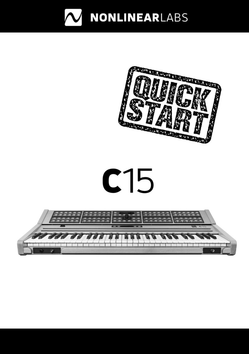
Elka MK88 User manual

MK88
MK55
MASTER
CONTROL
KEYBOARD
ELK
A
wtHrld
Isko
lo
thank.
you
for
ctiaossrog
ibc
MK
8S.
5S
Master
Control
Keyboard.
Considered
l
brought
ut
ihe
world
as
tuitd
lh-'
rook
versatile,
I
his
instrument
has
t>:-en
specially
designed
to
control
nil
types
ol
Ml
Li
l
mtuipn
unf,
presenl
and
future,
and
is
indeed
areal
''Opvwii&rw!
Ccnlrv!
Cvfitnf".
This
manual
lias
been
carefully
compiled
!n
ensure
lhal
you
obtain
rhe
v<jry
Ijest
results
from
ll’n;
MK
8&f55
a
nd
w-d
iui.uJ
.in)
|lial
you
read
11
thorcughly
beicre
us«ng
the
instrument
INTRODUCTION
The
Ei.KA
MK
tfttbb
is
a
master
control
keyboard
specifically
designed
to
control
up
Jp
T2
t
omparibli*
units
ny
means
of
I
he
MIDI
data
transmission
system
ihese
unis
an
Include
expanders,
keyboard
synthesiser^
sequencers,
rhythm
unite,
petfalboardsand
J
ny
spiral
effecls
units
such
as
reverberation,
etc.
In
ibis
way
a
complete
MIDI
environment
can
Iv-
sui
up.
canlmiled
and
played
from
I
lie
single
keyboard
of
the
MK
8B/55.
]
28
programmable
PERFORMANCE
PRESETS
art-
avfnlabte
I
hew
are
grrvipwl
into
4
internal
banks
r>l
lb
and
A
external
banks
of
IS
which
are
stored
in
a
RAM
cartridge.
I^t:h
PERFORMANCE
PRESET
mertinn^es
all
Hid
pnsfjramrnaple
functions
(SPLITS,
MIDI
CHANNELS
DYNAMICS
etc.)
and
contains
a
"Set
Up
r
'
memory
which
controls
(be
whote
MIDI
envirunmenl
fPRO¬
GRAM
CHANGES.
VOL
LIME
SETTINGS.
SONG
SELECTION
and
so
on).
A
32
character
Liquid
Crystal
Display
enables
you
to
keep
all
the
various
changes
under
control,
as
each
operation
i*
automalfcaily
visualized
lhe
mstruintrn-
makes
use
of
numerous
'REAL
TIMT"
controls
which
permit
the
manipjlulion
of
any
function
in
a
MlDi
system,
including
continuous
control
of
RHYTHM
UNITS
and
SEQUENCERS
The
keyboard
can
be
split
into
6
zones
which
can
be
overtapped
as
and
when
necessary.
Each
of
these
"Split
2oi
c
an
be
pK.j&rammi.’d
..umpHiHy
differently
HIGH
RESOLUTION
DYNAMICS
with
HOL.V
PHONIC
AFTER
TOUCH,
midi
in
and
FULL
CLOCK
CONTROL
complete
the
specification
which
makes
ihis
trial
rument
the
mosl
complete
MASTER
CONTROL
KEYBOARD
yet
obtainable.
]

CONNECTIONS
FIG,
1
DESIGN
0
F
BACK
PAN
EL,
SHOWING
ACCESSO
R
Y
COM
N
EC
TIN
G
D
ET
AILS.
O
O
9
O.ALO
W
l
__,
f
_
—
_
-
_
t
To
AC
|)f.W!r
VX-fl
MIDI
Five
separate
D3iK
sockete
vail
be
seen
under
the
heading
MIDI,
Two
each
for
MIDI
OUT
1
and
MO
GUT
2,
and
enn
Inr
MIDI
IN
MIDI
OUT
Brnn^
a
Master
Cnnlro
KeyrraFird,
this
instrument
doss
not
have
an
uudLt
uutpui,
ir
l
hat
by
itsdl,
il
ts
no".
capable
of
producing
sounds
as
such.
T
he
reason
for
this
being
that
no
sound
generator
Is
present
in
Line
instrument
ilscll.
All
ihe
sounds
Ihal
are
produced
are
depended
on
the
specilicetKins
uMhu
mstrLirnents
connected
via
MID!
The$£
connections
cm
be
made
by
means
of
the
MIDI
OUT
sockets,
MIDI
0U3
1
and
MIDI
OUT
2.
Two
sockets
for
both
MIDI
OU
I
L
and
MIDI
OUT
2
are
provided.
(See
MIDI
CONNECTION
EXAMPLES
section
for
further
Informal
ion).
From
these
two
pairs
of
sockets,
all
the
MIDI
da:a
necessary
to
set
up,
control
and
play
Ihe
various
Junc¬
tions
or
any
MIDI
compatiOle
Instrument
(EXPANDtH,
SYNTHESIZER.
PEDAE.BOARD,
SEQUENCER
elu
)
will
bo
transmitted
Oh
a
lOSSl
Of
32
completely
independent
channels.
Furthermore.
The
MIDI
OUT
2
sockets
also
provide
a
MIDI
CLOCK
ouipul
for
use
wilh
RHYTHM
UNITS
&r.fl
SEQUENCERS
etc.
(See
MIDI
CONNECTION
EXAMPLES
for
information
On
the
connection
of
these
units).
MIDI
IN
When
r>n
eternal
MIDI
CLOCK
OUT
is
connected
tolhis
Input,
the
DELAY’EC40
and
LOOP
fuiiLtiuris
of
Ihe
MK
S&bb
w\
be
automatically
synchronized
with
this
and
ai
the
same
time
Ihc
internal
clock
will
Ixs
disconnected.
The
EXTERNAL
CLOCK
inc'icalor
(on
the
extreme
left
of
the
panel)
(1)
will
show
lhai
an
external
dock
signal
hfjs
ueen
connected
2

CONNECTIONS
earn'd.
This-
socket,
wh.-o.ri
cun
netted
to
the
MID!
OUT
of
an
external
instrument
will
enable
this
same
insifumenl
[Keyboard
or
Pedalbaarrl)
1o
l?e
aeded
to
the
conlml
system
of
the
MK
#S''S5.
In
this
ease,
all
Hit
fund
.on
5
programmed
jnio
the
Spirt
Zones
5
and
Swill
Lc
vijlid
Ipr
this
external
Instru¬
ment
Tins
Includes
all
the
DELAWECHO
and
LOOP
functions.
Foi
more
L-zpliiil
in'urn
id
|
ion
on
the
iibH
uf
MIDI
iff
you
should
read
die
MIDI
CONNECTION
EXAMPLES
section
further
ahead
Alt
connections
mad*
between
(he
MK
8t5
;
55
and
external
units
must
be
made
with
PIN
standard
Mflif
connecting
cables.
i
his
is
the
corwectfon
recommended
far
(he
Initial
sotting
up
procedures.
Other
more
complex
connection
examples
can
be
found
in
the
relative
section
further
ahead.
PEDALS
Two
jacks
marked
PEDAL
1
and
PEDAL
2
are
to
be
found
on
the
extreme
fell
of
Ihe
hack
pane!
(SwFLG.
1).
rhese
provide
connecting
facilities
la
the
two
analog
pedal
devices
(VP
10,
optional
extra
)
which
can
be
used
to
control
various
funelkins
in
(Tie
PEDAL
SECTION
of
the
GENERAL
CONTROLS
These
functions
can
be
seen
in
1
he
GENERAL
CONTROLS
section
of
the
Matrix
Control
Panel
fSJ.,
under
the
heading
Df
PEDAL
Further
explanation
of
Ihe
functions
controlled
by
thnse
pedals
Is
to
be
found
in
rho
section
G
E
N
Efl
At
CO
NT
ROL
S.
furl
tier
a
I
read.
FOOTSWITCH
ES
Up
tfi
lour
foot
swilches
[MP
7
type,
optional)
can
to
connected
to
the
MK
&S/55.
The
functions
controlled
by
to*
of
these,
FOOTSWITCH
1
and
FOOTS
WITCH
2
are
programmable
bv
making
reference
to
Ihe
line
of
functions
corresponding
to
FOOTSWITCH
in
Ihe
GENERAL
CONTROLS
pirt
ol
the
Matrix
Control
Panel
(5),
Further
details
are
contained
in
the
GENERAL
CONTROLS
section
further
ahead.
The
remaining
two
sockets
a
r
e
used
for
Ihe
connection
of
two
ol
the
same
type
or
fooEswitchos,
but
in
Ihfcse
iwn
rases
to
perform
sp.-rilir
n
motions
One
nt
these
is
used
tn
enable
an
advarcomenl
of
the
PER
FQRMAWCE
each
time
the
switch
is
pressed
(PERFORMANCE
ADVANCE}.
The
Other
socket
marked
FIJLl
used
Lti
activate
nr
deactivate
Inis
same
J
unc1ion
MEMORV
CARTRIDGES
The
RAM
MK
cartridges
should
be
inserted
into
their
appropriate
pxil
on
ilia
fronl
panel
£22},
Each
carl
ridge
is
capable
of
Storing
64
PERFORMANCE
PRESETS
grouped
into
4
banks
ol
lfi.
CVtAINS
Connect
1.1
io
power
supply
cable
lean
A.C.
voltage
output
socket
of
the
correct
voltaic.
3

CONTROLS
SPLIT
CONTROLS
(6)
r
-
fie.
:i
SKIT
CON
EftOLS
SECTION
OF
CONTROL
MATRIX
Altar
conneciing
me
instrument
to
an
expander
or
syntecsi/er
via
I
her
MIDI
OUT
L
socket
on
Hie
back
panel,
iwilch
them
ooih
on
The
normal
opc-ratirg
mede
oi
hie
instiument
&
(.tie
SF^L.iT
.MODEL.
This
means
that
the
keyboard
can
t>
spill
into
3
maximum
oi
six
separate
zones,
wricM
leu
be
Independently
proj^mmed.
I
si-*
olhn
nwtfc
1
is
the
Ft
LL
MODE
which
enables
the
voices
of
each
si'll
to
sound
over
site
full
oxtanl
oi
II
m
kuytKtiKL
As
oil
tile
SPl
IT
ZONES
that
yon
program
can
be
acllvalird
in
the
SPLIT
a-ndor
HUL
L
MODE.
you
have
three
r^tete
w^ys
to
use
each
SHJI
ZO^L
1.
SPLIT
ON
FULL
OFF
The
sound
will
only
bo
j<
live
in
the
SPLIT
MOOT
(in
the
retevami
SPLIT
ZONE!
but
not
in
the
FULL
MODt
2.
SPLITON
FULLON
The
sound
will
bo
active
in
both
the
SPLIT
MODE
(in
ltie
relevant
SPLIT
ZONE}
and
(he
FULL
MODE
(across
me
whole
keyboard
I.
3.
SPLIT
OFF,PULL
ON
The
sound
wall
be
only
be
active
in
Ihf
FULL
MODE.
I|
b
iheiulbfo
possiblu
to
proftMin
the
MK
8&S5
and
n's
associated
external
unK
SO
that
completely
dilfe-
rcnT
■
sou*i*:Js
active
across
l
ie
kcyboaitt
in
me
SPLIT
anti
FULL
modes
To
make
use
c-r
She
FULL
MODE
you
shoo
d
connect
an
MP
?
teolswfch
ioptiunai
extra}
to
the
FULL
socket
on
Lhe
tack
pan#
o!
the
Instrument
In
ihi*.
way
.in
die
SPLIT
ZONES
that
you
program
in
ilm
Fuu
MODE
will
be
made
to
runctxm
or
(he
entire
length
oT
the
keyboard
when
you
activate
this
footswilch
tl
one
of
iluj
SPLIT
ZONES
programmed
does
mil
iliny,
you
should
check
lhai
n
has
been
activated
correctly
Ai
this
pent
you
should
teikw
Ihe
instructions
below,
very
c^rtJ'uiiy,
in
order
to
obtain
an
nitial
setting
li
tills
way
yju
wrS
be
in
a
position
to
siart
ptaying
on
the
keyboard
ann
Ih^n
pi-oytl
to
all
ihe
other
uanw
selling
up
operations.
Fo<
the
purpose
of
Ibis
initial
setting
up
praeoelurf,
you
will
ho
programming
the
MK
88
55
with
one
SPLIT
ZONE
(SPLIT
1}
end
Ibis
will
bo
transmitting
on
MIDI
CHANNEL
1.
SPLIT
POINT
1.
Press
one
cl
the
buttons
£1*16)
m
the
row
□
(
Pultons
under
Ihe
central
matrix
oT
oontrofs.
2.
rV'r,-.
PANEL
«in
Hio
?
,lronx‘
right
of
|*it
COrltralb
in-!
!
fmglln*
tad
II'
li
diet
light
to
thuSPL'l
KJlNl
jK.i'jtn:"
b
r
moans
oT
ihe
UP
.‘DOWN
buttons
A
V
(15)
[see
Fig.
4
on
page
5)
found
under
tr>u
control
indicatin'
lights
or
the
Ml
of
me
cenlrai
tomrat
matrix
I

SPLIT
CONTROLS
coin'd.
(SPLIT
POINT)
FIG.
4
PANEL
DETAILS
(WITH
UP/DQWN
BUTTONS
ON
THE
LEFT,
ALSO
USED
FOB
PERF.
SLQ
f
1
f
wr'l
pimivior
P
MJiiHU
K
1
CHHWI
dTHllW
jijpri
■
iniiTH
•-*H
4
f—!d
TP
-
u:
pwrrniT>i
i
l
puwriHpi
i
fiU«L
UCfl
i
T
3
II
MLJiM-T-O
•IDO#-
I
#
4
^
■
**
Hi—.
w**
y
F
+I
■
fa
■
-
4
i
■
'
b
I
p
1
,p
UfrDGWN
BUTTONS.
(15>
PERFORMANCE
PJCSCT
SELECTION
BUTTONS
UG>
FULL-SPLIT
O.N.YiFF
Lused
Id
n
imc
ed
indicator)
BUTTONS
It
should
be
remembered
that
to
make
any
editing
operation
you
should
first
press
the
PANEL
button
(11)
and
then
move
the
indicator
light
tothE
desired
section
in
parts
(5)
and
(6)
on
matrix.
3,
Pmi$
SPLIT
1
-in
tin?
BANKS'S
PL
IT;
FREE
(19)
RWp
Ol
buttons
w
the
lower
right
hand
sme
of
I
he
con!
ml
panel.
4-
Lhe
SPLH
^ONE
should
now
be
achvaled
in
one
or
bolh
of
the
two
modes
using
)he
buttons
corre¬
sponding
to
SPLIT
ON
aid
FULL
ON,
It
should
be
remembered
that
Ll>£
functions
assigned
In
each
SPLIT
/ONE
will
only
heoperaliue
when
playing
in
an
activated
mode
fer
each
respective
SPLIT.
Ihat
fe
SPLIT,
FULL
or
both
r
IG
h
EXAM
PL.
|
t)i
VIA1K
JX
CUM
I
KOL
SYS
I
EM,
ACIIVA11
ON
W
Shi
<!
ON
MODE.
—
tf
5
l
mil
run
I
Hitt
*
l«J„«/iJ.
v
m
CHinEL
w
frl»UUftL
■
■
r
ir
h
icixh
4
m
*
I
a
i
i
rfVHI
■
-
■
AT
Ml
iwt'«>
■
raw.
kLrixi*
MlA-ICMI
■
if
-
W
%l
H
i
■
i
Press
IMb
ballon
B

SPLIl
CONTROLS
cont'd
(SPLIT
POINT
1
II
is
advisable
That
>tw
uttaSPLJ
•
ZONE
activated
over
the
entire
freyboard
if
itiahy
to
li-o'gi
you
tu
become
Limilinr
w,lh
;iH
Ihj-'vurims
functions
wthaiil
beconing
involved
m
I
he
keyboard
spliLtinft
process
li
should
1
x
1
remembered
Uiaiin
ell
me
soiling
up
procedures
to
b&rained
on'
cm
the
m.»n
Lj&ntiHjI
main*
having
Trst
KHvated
Hv.
1
PANEL
mode
button
(11}
as
explained
earlier,
you
should
then
irwvc
th?
uwf
f
at&f
h(jlit
UP
and
DOWN
according''/
to
indicate
fl»
ObnlroJ
that
you
war
l
to
w!
up
Al
this
t»n(
you
siKiuld
UIm:
care
:u
select
trie
SPLIT
ZONE
iii-il
you
w.v-r
to
ore-gramme,
by
means
of
the
SPLIT
Sjullons
in
irm
HAWfc'5
PUT.'FREE
groupal
buttons
(19}
and
then
folkw,-
the
separate
insEmctrons
ftr
each
function
You
can
now
proceed
w-tfi
me
initial
selling
up
of
the
keyboard
as
(ollews-
After
assunng
I
hat
ilia
red
mdicaior
l-gin
is
iLashlng
in
the
SPuT
POINT
[Hellion
proceed
as
r<rilnv*y
1,
P
res?
SPLIT
1
in
[tie
BANK/SPlLtfFREE
group
ot
bullions
(19)
on
the
right
o'
ihe
display.
Hard
liu.
button
down
until
die
display
changes
t&:
proas
lovast
■
P
:
1
.
A
-
-
2,
P
ress
the
(barest
key
requited
n
flit
SPl
IT
ZONE
and
[fie
drsp'ay
w.
I
change
r.j
;
p
£
&
s
3
highest
P
:
1
.
A
-
-
3.
A
t
IIus
i&cjnL
pness
Ihfi
highest
tujy
required
m
tins
SHU1
ZONE
Having
dona
thEs,
you
will
have
set
Ihe
lowest
and
highest
limits
of
the
ZONE
and
Hus
extension
will
now
bo
shown
cn
[tie
display
a
r
>
shrjivh
bdte-w:
1ms
dapiay
example
it,
showihg
a
Tull
keyboard
e>1en$i-3n
foe
SPLIT
1
on
the
FZKSS
model
(A
-
C7)
Split
1
A
-C
7
P
:
1
A
-
-
Feu
the
initrjl
setting
up
procedure,
you
can
rgnore
Ihe
second
SF'Lll
CON
I
ROL
r
rival
iy
TRANSPOSE,
a^d
h
i7ju
directly
down
!o
the
MIDI
LMANNEl
eonteii
by
u*
int
DOWN
bullon
V
(IS)
(net
Fig,
4),
e

SPLIT
CONTROLS
cant'd
MIDI
CHANNEL
After
assuring
that
the
rod
Indicator
light
is
flashing
in
the
MIDI
CHANNEL
position.
you
are
now
a
hi*
1
tn
programme
The
(i-ansmission
channel
for
cadi
ol
the
SPLIT
ZONES
on
Ihe
MK
6B/55.
Remember
thal.
Ihri
MIDI
CHANNEL
musi
be
the
same
on
both
the
MK
B3-'55
and
lhe
external
unit
that
i&
being
controlled
for
each
respcc
live
sec
lion
This
will
ensure
Ihe
transmission
of
all
fnedata
Lhal
you
programme
1.
Press
111=3
tuition
corresponding
(o
OUT
1,
the
penultimate
Irorri
the
right
in
me
row
ol
buttons
witter
Ihe
central
matrix
[16).
This
is
very
important
because,
for
Ihe
initial
selling
up
procedure
you
shourd
have
connected
to
Ihe
MIDI
CUT
t
sodte;
on
the
MK
R&'55
[see
Fig,
1
and
Fig.
2
an
pages
2
and
3).
No
soLrnri
will
be
heard
if
Ihe
MIDI
CHANNELS
have
not
been
programmed
to
the
appropriate
MIDI
OUT
socket
2,
Press
the
button
corresponding
to
Ihe
MIDI
CHANNEL
(hat
yOo
wafll
(0
assign
to
ihe
SPLIT
ZONE
irdi-
caled
on
Ihe
display
(In
this
initial
procedure.
SPLIT
1
)
Remember
that
you
must
assign
a
MIDI
CHANNEL,
from
1
-
16,
to
all
the
programmed
SPLIT
ZONES
when
completely
programming
the
instrument,
after
having
done
the
initial
setting
up
which
is
ossenlial
to
make
die
instrument
play.
M
you
now
play
on
the
keyboard,
you
will
hear
Ihe
voice
lliat
has
been
programmed
nr
the
external
unit
(expander,
keyboard,
pedalboatd
do.)
that
you
have
connected
to
the
MK
if
you
do
not
hear
any
sound,
cheek
that:
a)
I
hit
MIDI
cabin
Is
connected
rwrealy
(o
Iho
MIDI
OUT
1
socket.
bj
thif,
cable
is
connected
In
LIig
MIDI
IN
socket
on
Ihe
external
umt.
o)
SPL
s
T
J
has
been
activated
[SPLIT
ON),
[See
point
4
in
SPLIT
POINT
on
page
5),
d)
She
MIDI
ON,
'OFF
hulten
has
been
activated
if
you
are
using
an
ELK
A
moduli!-,
o)
lhe
MIDI
OUT
and
VflDI
CHANNEL
assignments
have
been
camecont
correctly.
f]
ih«
connections
between
the
external
uml
and
Hie
power
amplifier/mixef
have
lH?en
carried
out
correctly
iiMd
Lhal
ihese
units
have
been
turned
on.
11
all
is
well
you
can
piocetKl
lo
the
programming
of
1
he
oilier
SPLIT
CONI
ROL5:
TRANSPOSE,
DVNAMtC
and
AFTER
TOUCH.
TRANSPOSE
To
programme
a
transposition
s>ou
should
move
the
indicator
lighi
to
TRANSPOSE
by
means
nt
ihe
LIP,'DOWN
buttons
A
T
[15)
a
net
then
proceed
as
follows
1.
I
ir;
I
press
SPLIT
1
in
the
BANWSPLITyFREE
section,
U9)
a
make
sure
measure
in
case
other
splits
have
been
selected
during
previous
programming
and
make
sure
that
il
has
been
activated.
[SPLIT
QN
and'or
FULL
ON)
2.
II
you
want
to
carry
out
a
positive
irons
position
(raise
ihe
key)
(hen
press
button
number
1
(16),
this
correspcnds
to
SET
+,
At
this
point
(he
led
indicator
In
button
l
posilton
will
be
flashing
and
the
display
will
show
this
message;
sat
po
9
.
transp!
F
!
1
A
-
-

SPLIT
CDMTROlS
loi
itU
[TRftNSPOSEJ
You
should
now
press-
one
of
the
leys
on
the
keyboard
1o
make
a
posilive
transposition
ustrrg,
the
lowest
C
key
as
a
reference
point
Tor
example
if
you
want
to
transpose
ttie
keyboard
ty
one
octane
then
you
should
press
the
key
ihal
is
one
oitave
higher
then
bollom
C
Pressing
(he
owest
F
w
i|
shew
+
0.5
on
display,
second
D
-
+1,?
octaves
and
second
G
-
+-
1,7
etc.
These
readings
are
expressed
in
octaves
nil
til
Vi?
Delates.
Having
done
Jhis
r
the
SET
+
red
will
be-
turned
olf
and
the
TRANSPOSE
ON
indicator
turned
on
la
inform
you
that
a
transposition
has
been
programmed
and
the
Tot
Irving
display
will
be
seen
Split
1
+
1,
0
p
;
l
a
-
-
By
the
same
means.
H
you
want
to
make
a
negative
trarsposifon,
proceed
a-i
follows:
1.
Press
SET
-
r
corresponding
to
button
9
>
n
Ihe
central
row
ol
buttons
f
Eft},
The
display
wtl
I
now
sin
fw
sot
nog.
transp!
F
;
1
A
-
-
2,
As
fn
ttie
positive
transposition
procedure,
press
one
of
the
keys
on
(he
keyboard,
txit
Hits
lime
using
1
lie
highest
C
as
a
reference
pant.
For
example
i(
you
reejuire
a
negative
transposition
from
C
down
to
A,
(lien
press
the
A
key
immediately
below
the
(op
key
(Cl.
(Display
will
show
0.3).
If
you
need
in
transpose
down
by
one
octave,
then
you
should
press
the
tey
lhal
Is
one
ocl.ive
below
the
top
C
on
the
keylwartM—
1,0).
Having
performed
Ihis
negalrve
Eransposlion,
ol
one
oc'ave
rcr
example,
the
display
will
r.hnw
the
following
inforn
alien
Split
1
-1,0
P
:
1
A
■
—
—

SFU
1
CONTROLS
coin'd.
[TRANSPOSE]
The
transposition
that
you
have
programmed
boebsactivated
by
means
gf
1
he
bullon
marked
ND„
cw-
r-ispqndirvg
lo
TRANSPOSE
OFT
grid
be;
made
operative
Jgfliil
When
rCguKaJ
by
prr^jriE
VE;$
t
cOrre-
sl'iDhdin^lo
TRANSPOSE
ON.
$e<>
FIG.
GtbelcnvJ.
y
w
VIS
1
TRANSPOSE
ON
OFF
■
H
M
mm
buttons
it
wt
/caff
Hiw\
/
f
OiPlK
i'fliistei\
f
transpose
nr?
\
IRAN&PttSEON
When
diaacli
voted
the
dismay
will
sii-cw
ltic
normal
sp'il
range
o'
SPLIT
ZONE
!
|
RANiPW
OFT
tHANSPOSE
dN
Split
1
Vi
1
A
c
1
-
C
«
Split
1
Pi
1
A
+
1
,
0
DiipJay
fijiarnplfrs
for
a
one
gcbvc
po^ttivi;
(raojpfltitifln,
DYNAMIC
Vlju
Have
19
dillerenl
dynamic
resporses
Citable
far
selecting
and
asstfirirnerit
to
each
SPLIT
£GNC
Hie
lir^i
fl
fiti
■
pcsiliyg
cufYfrS,
wnJch
means
that
Hie
haed(r
you
phry
:hr.-
higher
Iho
dynamic
value.
Tho
second
a
dynamic
responses
are
curves
which
worn
m
an
inverse
way,
these
arc
calico
nesalivc
cur¬
ves.
When
you
select
ene
r;1
Hiese,
playing
the
Keyboard
tightly
will
r^auit
m
a
ii
gh
ctynam-c
value
whilst
Harder
playing
will
decrease
the
dynamic
value
proiwitionalry
according
lu
the
curve
chosen.
These
are
followed
Jjy
two
fUed
levels
corresponding
to
1/3and
2/3
of
Ihe
maximum
level
and
DYNAMIC
VALUE,
I
tie
control
0
!
which
when
selected
l
an
be
assigned
to
the
PEDAL,
WHEEl
U31
and
SLIDER
(2)
Donlfols.
This
procedure
is
fully
captained
m
the
GENERAL
CONTROLS
section,
the
use
ol
two
superimposed
SPLIT
ZONES.
one
having
a
positive
curve
and
thegther
a
negative
curve
wilt
result
m
I
he-
loaiow.ng
Liglil
playing
will
enabe
one
offezt
to
be
heard,
playing, h
cavity
will
result
in
this
decreasing
and
|lic
other
el
fee
l
being
heard
while
pitying
with
mnrfum
press
jo;
m
lire
keyboard
will
(liny
l>:iS»i
riffrHiS^sisiiiiiri-t-
neously.
The
DYNAMIC
SENSiT
iviTV
oi
ihe
keyboard
can
bo
varied
to
yeur
liking
by
moan
i
on
ho
relative
control
on
I
he
hack
panel
(Sec
Fig.
1
on
page
Z>.
Willi
tins
wilroi
turned
lotozirds
liie
-
side
r
the
keyboard:
will
acquire
a
narcer
response
lo
lho
curves,
pro
jammed
whereas
when
Turned
Towards
ihe
-s-
s.ae..
this
response
will
become
more
spontaneous
and
the
keyboard
will
appear
lo
be
tighter
r
i

5PI
IF
CONTROLS
cont'd.
(DYNAMIC)
Jo
select
these
dynamic
responses,
you
should
press
PANEL
(11]
and
then
move
I
lie
flashing
led
indica¬
tor
\o
the
DYNAMIC
position
In
the
SPLIT
CONTROLS
section
of
the
central
cunlrbl
matrix.
After
selecting
ine
SPLIT
ZONE
Ilia!
yoiJ
want
to
program
by
means
of
the
SPLIT
selection
buttons
in
the
BANK/5PL
IT
FREE
group
of
buttons
(19)
lo
he
found
on
(tie
right
of
the
display
press
the
billion
corresponding
to
Lire
DYNAMIC
RESPONSE
hat
you
want
Louse.
N
B.
if
selected,
DYNAMIC
VALUE
must
be
4$$igaed
to
j
control
ns
explained
In
the
GENERAL
CON¬
TROLS
instructions.
wf.ii
r-
rt'niia
£
l
i.
'•
■
Pi
IT
CONTROLS
SECTION
01
CONTROL
MATRIX
f5h[?win£
DYNAMIC
hnd
AFTER
lOLOl
uivkI
AFTER
TOUCH
TJyg
polyphonic
AE
TER
TOUCH
facility
featured
on
tins
Instrument
is
a
mnans
of
controlling
various
para¬
meters
by
varying
the
amount
of
pressure
applied
to
the
key
after
actually
playing
a
note.
This
facility
is
divided
into
two
sedans:
L....8
Response
curves
wilted
tailor
the
effect
to
your
Individual
requirements
9...
17
The
various
functions
at
your
disposal
N.B.
N
fll
s
1
-
4
are
positive
curves
whorens
N
Q-
s
5
-
3
are
negative.
This
means
that
when
using
the
PITCH
BEND
effect,
for
example,
increased
pressure
or
the
key
will
cause
a
rise
En
pitch
with
curves
1
•
4
and
a
felt
in
pitch
with
curves
5
■
§.
The
MK
38/55
Incorporates
Hie
rare
facility
ol
being
able
to
transmit
POLYPHONIC
AFTER
TOUCH
infor¬
mation
which
only
affects
the
particular
note
or
notes
that
e*!ra
pressure
is
applied
to.
il
the
external
unit
or
units
connected
to
the
MK
80/55
do
not
have
Hie
specification
to
receive
this
POLYPHONIC
informa¬
tion,
then
the
TOUCH
POLY
mode
should
net
be
used
as
il
will
net
function
To
check
I
hi
ft,
you
should
consult
I
he
relevant
owner's
manual.
To
set
up
the
AFTER
TOUCH
function
you
should
follow
this
procedure:
Al'rr
pressing
PANEL
(11),
1.
Move
indicatorlight
lo
AFTERTGUCH
by
means
or
UP/DOWN
i,
T
buttons
(15).
2.
Select
hie
SPl
IT
ZONE
lhal
you
are
selling
up,
by
pressing
one
of
Ihp
SPLIT
buttons
Tram
1-6
in
Ihe
BANWSPLlT/FREC
group
of
buttons
(19).
3.
Activate
the
ATTFR
TOUCH
function
by
pressing
Lh&
button
corresponding
to
ON
(extreme
right
in
I
he
line
nl
control
bullous
under
the
central
matrix,
4.
Select
feu
typo
of
response
that
you
require
by
pressing
one
of
the
buttons
1-S
corresponding
to
the
response
curves
of
the
AFTER
TOUCH
10

SPLIT
CONTROLS
COfltU
(AFTER
TOUCH;
4,
Chyoi«
rhu
rt.nchor
Ittst
y-r'iLj
wart
in
ronlroi
by
pissing
one
or
(lie
remaining
butt-cnc
occluding.
ific
Fiisl
two.
Ihese
are
used
to
activate
and
diraclfrate
the
AFTER
fCHJOH
function
TOUCH
CHANNEL
TOUCH
POLY
MODULATION
PITCH
r
OOT
CONTROL
VOLUME
0
1
ft
VOLUME
\{A
-3/4
VOLUME
V2
FULL
VO|
LJME
D-
FILL
OTT,
ON
This
function
should
he
selected
if
you
want
tc
have
a
normal
AITCR
TOUCH
mriimJ
This
means
mannj^hr>nc
conlrot
for
eadi
SPLIT
ZONE
If
you
want
tc
cunrc-cH
an
external
unil
capebte
of
receiving
pulyiifit-His:'
AFTER
TOLfCH
intormalian
you
can
use?
(he
function,
otherwise
^su
must
Use
"OUCH
CHANNEL
The
AFTERTOUCH
mil
control
the
MODULATION
function
of
any
eAtnml
umt
when
this
button
has
been
selected
PITCH
wII
be
-controlled
by
the
keyboard
AFTER
TOUCH
<f
you
haw?
sefecico
Dts
function.
When
selected
lliis
Junction
wil
work
as
an
erpresaon
pndal
rcmlroiled
bv
the
AFTER
TOUCH,
These
four
VOLUME
ranges
when
sheeted
will
tie
covered
hy
the
AFTER
TOUCH
facility
and
vMl
act
35
a
volume
CDnlFOF
on
(Pe
SPLIT
ZONE
bo.
Which
they
have
byen
assigned
Usud
to
activate
and
CiSMllvalfi
Ihe
AFTER
TOUCH
as,
explained
earlier
JV.a
The
TOUCH
CHANNEL
OlNt
TOUCH
POLY
functions
cotilfai
She
AFTERTOUCH
effects
which
haw
been
programmed
into
the
relevant
external
unite.
Tlw
other
functions
omride
the
AFTERTOUCH
effects
that
have
been
programmed
into
the
external
wits,
end
activoto
the
ones
programmed
Mo
the
MR
88
55.
GENERAL
CONTROLS
(5)
FIG
7
GENERAL
CONI
ROLS
*
T
1
1
■
r
I
*i
H
ii
■
■
ik
^
1^(4
mu
n
■
f.h
ub
lb
uj
i
The
GENERAL
CONTROLS
saclioti
<5>
of
she
Contro
Mains
Is
dedicated
In
|heassignment
of
the
2
FOOT
SWITCHES,
4
FUNCTION
Ksy*
(14],
2
PEDALS,
3
SLIDERS
end
2
WHEELS
ELS)
to
the
control
of
various
fund
inns
in
Ihe
SPLIT
ZONES
I
-
tar
1h4
A|
f
F
R
N
A"
E
MIDI
channel.
In
Ollier
wards,
it
enables
you
lo
chOttte
which
controllers
will
tran&mlt
the
vanOus
MIDI
codes
necessary
IP
control
the
eternal
units.
As
menloned,
these
controls
car
be
assigned
Id
activate
the
various
Mellons
in
&
SPLIT
ZONES
{one
or
mure
I
nr
if
needed,
so
transmit
a
MIDI
cede
on
an
AL1ERNAIL
channel
which
you
can
select.
(E*piami
Iron
furl
I'Of
ahead).
II

GENERAL
CON
RQLS
ccnld,
FOOTS
WITCH/FUNCTI
ON
You
can
urogram
'he
2
FootswilchesOncM
Function
keys
(14)
to
control
tlw
rollcwhB
functions?
SUSTAIN'.
PORTAMFNTO,
SOSTFNI
TO,
FIOFT
MODULATION,
PROGRAM
CHANGE,
ELK
A
PROGRAM
NOTE
QNVOFF
and
FREE
A
6,
C
r
D,
The
HILL
A.
Id.
C
and
D
luiicirorct
aio
fuliy
programmable
and
can
be
inade
lo
SJe«rforiri
any
function
in
ths
MIDI
environment,
PEOAUSLIDERWHEEL
You
i*ugr
c
innni>
the
2
pedals,
2
slide's
{2)
and
2
wfrieds
(13)
te
control
the
Following
funeliqnii:
VOLUME,
MODULATION,
PITCH
-
PITCH
+,
PITCH
±
TOUCH.
FC-DT
CONTROL
DYNAMIC
Vrtl
LIF
and
FREE
E.F.G
and
H.
Tlit-
DYNAMIC
VALUE
lunction
ljci
only
Lie
assigned
to
cute
af
the
controllers
i
J
seise
let!
in
lhti
SPLIT
CONTROLS
ssc'ion,
instead
of
the
Dvdaniit
cj"yqs,
(See
DYNflMJC
section).
The
TREE
E,
f,
G
and
H
functions
(as
A.
B.
C
and
D
in
I
ho
FOOTS
WITCH
i
FUNCTION
sections]
arc
FtiMy
programmable
To
pro.s.-arr
lliope
controls
far
me
$P_lT
ZONES
Tollftw
this
procedure
1.
Press
PANEL
Ul)
lo
enter
into
the
LOST
mode
«1
me
MK
&m>
2.
Position
the
lashing
tc
ndteator
on
the
control
to
which
you
want
(oesGign
the
functic
n
to
ue
contra
tod.
2
.
Select
the
appropriate
SPuT
ZONES
using
the
Pultons
U
W
(1G)
te’uw
It*!
central
maln>..
{Fur
ALTERNATE
CHANNEL
assignment
see
further
a
head
5.
4.
Proas
the;
ballon
on
Ilia
boMcm
raw
correspond*
ng
lo
th?
MIDI
function
that
yflii
warn
to
ahili'atn
w
in
[lie
con
I
re"
already
selected
in
jwim
2.
In
Ihe
of
SUSTAIN.
PORTAMENTO.
3GSTENUTQ
and
SOFT,
when
programming
Ihc
FQOTSWITCH
and
FUNCTION
contnofs.
you
wiH
no)
be
asked
In
seteol
a
VAI
UE
as
inpae
are*
simply
ON.OFF
functions,
whsmw
far
MODULATION.
PROGRAM
CHANGE.
ELKA
PROGRAM
nnn
NOTE
ONfOFF,
alter
sealing
these
functions.
the
display
wifi
allow
Ihe
folrowing
message.
ent6£
viko:
Q
E
:
3.
A
-
-
5.
You
should
now
n-ntef
the
VALUE
required
for
ihe
parameter,
remembering
ih^t
Far
the
MODULATION
and
NOTF
ON/OFF
runclip-nfi
you
can
enter
all
values
from
0
127
while
Tor
PROGRAM
CHANGE
and
ElKA
PROGRAM
you*
tan
fnlcr*
ah
values
from
L
-
12&.
L
nese
values
can
be
termed
using
me
buttons
lo
be
found
Lfnder
the
Central
Control
Math*
from
1
-
9
and
the
0,
Ig
Us
Found
fourth
Irom
the
rij^hI
n
1hus
rnw
ol
pultons
6.
Press
DIRECTrEfUTER
(20)-.
The
display
will
now
vtsualizo
Ihis
message
For
Ihe
exfjTjtptH
iW
lirtvtt
entered
a
VALUE
a*
{id.
Edit
v
a
J.
:
6
4
<
IS
-
1
in
-
—
fnc
VALUE
llidl
you
entered
Will
now
Iltavo
h#«i»n
mpnnr
i/erl.11
Hie
ItuviiS
shown
oil
Ihe
Oisplijy.

GENERAL
CONTROLS
cont'd
To
program
Ihe
various
controls
lo
transmit
ihc
MIDI
cades
m
an
ALTERNATE
MIDI
chgjind,
fallow
Ihis
procedures
I.
Prfrs*
PANEL
f
11)
to
enter
the
PANEL
mode.
Z,
Ptisiliai
the
flashing
LEO
mdcalnr
nn
me-
contrn
to
which
you
wan)
to
assign
a
Function,
using
the
UP/DOWN
tuitions
(15)
(see
Ug.
4
on
page
5),
3.
P
rttss
ALTERNATE
(button
7
under
Ine
central
maliix'l,
Hidisplay
will
bioy<
st*wv
press
Channel
■
P
:
1
A
-
-
4.
Y
ou
should
now
select
lha
MIDI
CHANNEL
reemirod
for
the-
transmission.
by
pressing,
Ihe
corrcspon-
cinp
button
(1-16)
under
the
Cerlra!
malrix
(7),
press
mibl/oiit2
P
:
1
K
-
-
5.
A
t
this
perm,
press
OUT
L
or
OUT
2,
the
last
two
Suitorson
Ihe
right
under
Ihe
inaIri.K
[TGI,
according
tu
whth
output
yctr
want
lo
This
will
change
ihe-
disr
ay
lo:
I-nr
the
example
we
have
entotod
CH
13
and
OUT
l.
c
h
t
n>2
Vil;
64
P
:
1
A
-
-
Sliowinj'
yuu
thnl
you
have
programmed
CHANNEL
13
as
hie
MIDI
transmission
charnel
and
CUT
I
as
the
output
socket.
Ynn
should
™
>jw
designate
Ih*
function
that
you
want
tu
control,
making
your
selection
from
ihe
i&
functions
and
ft
free
available,
according
to
whether
you
are
using
Ihe
FOOTS
WTCH/FUNCTION
or
PEDALSL1DERFWHEEL
controls
try
pressing
the
aujwopriate
but
ton
m
the
row
of
buKons
under
Ihe
centra
I
control
roatr
*
(16)
sn
Hie;
same
wayes
lor
the
assign
mail
Iri
the
SPLIT
ZONES,
You
should
ado
J
cJluw
the
a
™
procedure
when
i|
is
required
to
enter
a
value
in
ihci
case
ol
Ihe
ftfODULATiQN,
PROGRAM
CHANGE,
ELKA
PROGRAM
and
MOTE
OM'OFF
Functions*
using
!ho
bultcns
from
1
■
9
anti
0.

GENERAL
CONTROLS
co-ifd.
DELAY/ECHO
Ti
i-
DELAV/ECH'O
iunclicirt
in
I
hi*
Inslrumenl
enab'esyou
to
obtain
one
delayed
rcplca
gl
I
he
trifling
note
played
ui
up
to
live
ECHOES.
Tbu
ifelay
liim*
of
both
or
tops*
pflc-cls
is
s/ncnroniiea
10
the
clock
fr«qn.>ri
cy,
troth
internal
or
external.
Wher
using
the
inte«n^il
■
clack,
the
TEVPO
slider
11}
can
ho
usen
y>
a
delay
lime
control.
Ik
diS-nlferM
Him
delays
are
anuialiK
which
an'
al
based
OH
functions
Cif
J
bar
u
;-.yed
Wilh
resOPCl
EtJfl
luted
tempo
in
Ihir.
way.
.1
you
selccl
1/4,
he
delay
lirrc
will
be
equivcldnl
lo
a
quarter
n
btv
p
ayed
.Ciii
iiio
TCMPO
set
al
Ihet
moment.
This
means
that
II
you
Us*:
TEMPO
at
n
Inwer
speed
the
delay
snunri
•*
ill
lie
Heard
a
Her
a
longer
time
period
ana
viccvcr&a
f
you
raise
ihe
I
lmk>
spoeri.
Td
program
DELAY
or
nog
f]l
Ihe
ECHO
effects
Into
Hit
SPLIT
ZONES
id
lew
this
procedure;
1
,
Move
H
e
Ifash
hr
indicator
Ighl
lo
DELAY'ECl-fO
by
n
tans
iti
ihe
UP-DOWN
buttons
(l
5}
once
ho^J-.g
programmed
fie
inSlrumc-M
in
rfin
PANEL
mode
by
prying
PANEL
CHJ
05
J
nr
all
Hue
main*
oro
Rr^rnminp,
2
,
P
tt-y-,
Hih
SPUT
ZONE
numbers
corresponding
IQ
incse
wttore
you
want
10
nf.e
the
DELAY.'LCHOel
reel,
tby
means
Of
bultons
1
■
Condor
the
matriji}
US),
3
,
Select
DELAY
oj
ECHO
elfecl
uy
pit-ssiii^
!
iu
reduce:
I-mc
button,
hrj
1
7
-
11.
!
;Cl
4,
Press
the-
button
correspond
ng
10
Ihe
lime
decay
that
you
require
ibullcr
12
onwards).
Tfoa
sound
will
now
be
heard,
whefi
playing
on
Ihe
keyboard
ThiswSl
eilher
be
one
delayed
nele
m
up
to
live
notes
according
to
wl
idhcrj
you
have
prctjarnrned
DELAY
yr
aneof
Ihe
ECHO
effects.
The
insiiiiniEFt
will
repraduco
all
tn&alteels
created
wdh
Ihe
SPLIT
A
GENERAL
CONTROLS
(5/61
On
(be
delayed
mu!
i
d
jnd
lilt
^irsl
note
reproduced
by
the
ECHO.
We-
adwHe?
yau
to
vaeci
Ihe
DYNAMIC
curves
/
>r
8
tor
the
nasi
realise
sound
when
using
Hie
ECH:i
function
N.B.
The
OELA
YfECHO
function
wfil
not
play
the
nb
to
at
the
instant
that
you
pfay
the
ftey,
tut
In
fact
with
j
EfELA
Y.
Therefore
in
order
to
use
this
function
to
the
maximum
you
should
program
two
SPLIT
ZONES
to
superimpose
one
another.
Then,
when
ypu
play
toe
hey.
on*
SPLIT
ZONE
wilt
be
playing
the
not?
Immediately
and
the
other,
with
toe
DELAY/ECHQ
time
delay.
You
can,
of
course,
program
the
“direct
SOrifld"
SPLIT
ZONE
with
a
different
sound
to
the
DEIAYSECHQ
cffotL
This
nil!
result
mu
really
original
sound.
LOOP
■
h
e
LOOP
function
enables
you
ip
temporarily
memorize
a
sequence
played
on
the
keyboard
up
to
0
length
or
A
bars
f
]
G."4}
r
I
ns
1
(XfP
will
hn
recorded
11
King
jhn
wands
programrrcct
mio
ihe
SPLIT
ZONES
that
are
activated
in
iho
SPLf
1
MUUL
Cwnh
Lh-
FULL
MOPE
.
LOOP
indicator
Ight
(8)
oil),
Wc
^ckise
you
Ec
conned
3
Rhythm
Unit
&uch
as
Ihe
ELKA
DRUMSTA3
80
lull
o.
ihslruir^nt
by
means
rsf
one
nl
llffl
it
7
sort's
nn
rhp
hnc-i
panel,
This
socket
w
H
provide
1
(to
CLLICK
cnnlrnt
for
the
Rhylhm
Uni(
Which
vjifl
bcfin
ploying
when
you
press
Ihc
START
button
(1)
on
Ihci
leit
of
the
MK
8&SS
control
ixme,
nl
Ihe
sanrellrTreKivirK
lilt?
START
command
kil
I
In?
ntourdinu
of
Pie
IflOP
Y;iit
'he
Rhythm
Unii
playingytxi
wI*
:hen
be
ab'e
10
recond
ttie
LOUP
ih
psr(Ht;t
terrpo
and
rrakc
full
u:^n
ol
1
her
LOOP
period
that
you
have
selected.
A
further
cssL-nt
mI
accessory
needed
for
Hie
LOOP
recoeding
operaiion
istliu
MP
7
Foolswilcli
which
you
should
pruj»
inloihn
Fill
I
srtckrt
on
the
back
panel.
Youwili
already
bn
fa
mi
ia
r
with
th
s
footswrich
as
yuti
will
h^vt
used
il
lr
she
activation
of
ihc
SPLIT
ZONES
that
are
orcgiammetl
irr
Ihe
TULL
MODE
M

GENERAL
CONTROLS
conl'd
(LOOP)
h
the
LOOP
letord
ng
process,
the
fouSiwitt.U
is,
u^ed
to
terminate
ihe
memoriitog
ol
If
is
LOOP
dud
enter
automatically
into
the
FULL
ViOOt-
cooling
you
in
piayover
the
LOGPv»sth
Ihe
SPLIT
ZONES
program¬
med
in
this
rnrxto
This
pcssmuiy
to
play
on
lop
m
what
ynu
haw
recorded
in
ine
LOOP
is
fiossibto
cn
toe
entire
keyboard
except
ttiu
towttSl
15
keys
on
ihe
MK
S3
aid
the
lowest
1
2
on
Ihe
MK
55.
Tlinsr?
am
used
tor
Ena
'PFAI
fEWE"
T^nspoa-lion
of
Ihe
LOOP
recording.
To
record
a
LOOP
seq
uence
ynu
shnuld
follow
I
hi'
procedure:
}
r
Press
PANEL
MIL
lo
Htlivare
"he
inslrumenf
in
ne
PANEL
<T[>rto,
2
.
Mow?eIie
Itotfiing
Indicator
lie.nl
to
Ihe
LOOP
position
by
means
of
Ihe
UP/DOWN
buttons
(IS)-
■
3.
Sdcct
IMc
required
LOOP
length
by
pressing
Ihe
appropriate
button
in
the
nollcm
line
under
IlKecdn
trol
matrix
{I-1G)
■
(16).
Yeu
must
remember
that
in
order
Eu
record
Ihe
LOOP
sequence,
you
shoo
d
have
activated
ai
least
one
hi
the
SPLIT
/ONES
in
the
SPLIT
MODE
explained
fl?nlifir.
Vcu
Should
a$d
activate
at
toast
one
of
I
he
SPLIT
ZONES
in
Ihe
FULL
MODE
rf
you
intend
Eh
play
on
Sop
of
what
you
iccorrl
m
the
LOOP
I
his
is
because
when
yon
presi
th*-
tontewitoh
Er>
tpimiiwlr?
the
loop
recording
and
enter
into
Ihe
FULL
MODE,
if
nd
SPLIT
ZONES
have
been
aclrvated
in
tfo.s
mode
These
^rll
r<?-nv>in
Sitonl
F
I
G.
H
DELAV/PCHO
AND
I,
O
OP
LENGTH
SELECTION
BUTTONS
4,
Press
START
(X),
which
will
both
'.Lad
the
Rhythm
Unit
playing
ard
activate'
ihe
MK
B&-S5
Into
the
LOOP
mode,
The
TEMPO
ol
Ihe
Rhythm
Unit
can
be
varied
by
the
TEMPO
cpntml
(I)
of
the
MK.
irt&'bb
A.1
this
pauil
ynu
are
ready
to
bsh
Mitt
ittcurding
ul
Ihy
LOOP.
CilKn
FIG,
“9
LOOP
CONTftOLS
(CLOCK)
&
r
Once
you
me
Mtislied
with
your
performance,
ycu
should
press
the
fwtswjtch
to
enter
the
Pi.A
v
P
ACK
mods;
lliih
will
cause
toe
FU^L
MGDE/LGOP
indicator
lighl
(S)
to
begin
flashing
Em
tins
mrxte,
The
instrument
wiH
autcmsltoally
rlA>t>dCfe
all
ihe
mores
play
art
n
tiara
I
DOP
rnndn
Nip
number
of
notes
reemdedi
w,ll
he
dependent
o-ri
the
lenglli
of
the
LOOP
selected
ir
point
3.
Yi;u
can
tipiv
pl
r
iy
pn
top
of
the
loop
recording,
using
ah
the
sounds
ard
ei’pcis
programmed
into
the
SPLIT
ZONES
activated
in
I
ho
FULL
MODE.
These
sounds
wi
I
haw
been
automatically
sclivaled
on
entry
into
the
PLAYBACK
mode,

GENERAL
CON
[
ROLS
conl'fl
[I
CGP}
STOfVCONTtNUE
-
START
[])
(1
you
want
to
stop
the
resperJive
playing
of
ihn
LOOP
wiinoul
cancelling
lhe
recording,
as
b
Lbu
case
when
you
qr^ss
the
FOOTSWITCH
a
Second
lirriu
after
living
played
the
LOOP
sequence,
then
you
Should
press
Hie
STOP
1
CONTINUE
button
once
to
stop
the
LOOP
and
once
again
when
yen
want
to
restart
it
again.
II
you
press
the?
START
button
after
pressing
thu
STDP/CONTINUE
button
I
hen
|3
ih
instrument
will
cancel
the
retooling
ot
the
LOOK
rpmo
our
el
the
FULL
made
ano
at
3he
sang
lime
start
the
R
by
Him
hum
tin;
beginning
At
Ihte
pair?
you
can
begin
resitmlinn
a
new
LOOP
sequence
using
Hie
sounds
of
the
SPLIT
ZONES
programmed
in
Hit*
SPLIT
MODE,
TRANSPOSITION
[luring
I
he
playing
of
the
LOOP,
you
carry
out
positive
transposition
o
:
the
recorded
sequence
by
usirg
the
lowest
C-fi
octave
un
Ihe
Keybos
m.
The
lowest
C
.s
the
normal
key
a
ref
each
key
upwards
from:
this
will
make
a
positive
transpcsilion
of
one
sernilono.
When
you
have
finished
the
programming
of
Hie
aba
1
.^
fcmcliOiiSi
press
ihe
PLAY
button
(2IS,
The
display
win
new
show
Ihe*
lallowiig
message.
LWPO
SPLIT
CON
pmou
y^ni.-.
-
WilMidny
dl
1
hr
rtn-3
alter
the
PERFORMANCE
PRESEl
N"
is
indicating
that
an
EDIT
cperalion
taken
plnen.
This
mil
always
bn
present
wfiesn
any
editing
has
been
done
and
not
yul
imnncr^d-
ntLEil
N-
BANK
N
rt
PERFORMANCE.
PRESETNAME
The
numbers
and
references
showm
in
lhas
display
arn
nM/ter
example
purposes^
the
actual
display
lhat
will
appear
after
qiessibfi
Hie
RLAV
button
{Zli
as
mentions;!)
oLxjw:.
wilt
depeivd
on
I
he
sellings
program-
nied
by
you
[Tempo,
Preset
N
n
,
Bunk
N<-,
etc.)
You
can
now
SAVE
everything
that
nas
been
sel
up
in
The
previous
praejamminKprocetJunes.
while
In
ihe
RAM
El
mode
T
hr>
siting
process
also
enables
you
to
rnur-uui/e
Hie
TEMPO
sewd
This
speed
can
Ini
vailed
by
means
qF
the
TEMPO
control
in
(he
CLOCK
section
U)
1o
be
lounc
«r
Ihe
toll
hand
stfc
ci
the
In;
i
r
panel
centrals,
I
he
TEMPO
speed
memorised
will
be
that
shown
cvi
(tie
display
at
the
moment
that
you
carry
Out
the
SAVE
operation.
To
yAvt
anything
d^ial
has
been
programmed
while
in
rhe
EDIT
mode,
lolicw
Hits
procedure:
Check
once
agam
that
the
irstmirenl
is
in
the
PLAY
mode,
then
press
SAVE
PERFORM,
(third
Frpm
the
right
in
Ihe
now
til
buttons,
under
the
cenlral
mat-ini
Keening
the
continuously
pfteStti
while
simui
laneoiiHty
pressing
Hie
button
corresponding
to
Hie
number
yl
Ihe
PERFORMANCE
PRESET
into
which
you
wool
to
memorize
the
complete
"Set
up
pl
(RemembB?
that
to
seler
-
a
PL
WKQWMANCE
PRESE
f
N
you
should
use
Ihe
rental
row
ul
buttons
[16).
The
sei
»p
will
new
have
been
rrcur-Dfized
In
Ihcr
position
selecled
as
will
be
seen
Rom
Ihe
display.
You
will
now
not
see
a
dut
aftor
the
PERFORMANCE
PRESET
N«
as
was
Ihe
rase
In
the
*1*
™
?
shown
display,
before
il
ti
memorizing
operation,
ins
indicating
a
metnorKed
situation.
Compteie
information
on
the
SAVE
PERFORMANCE
operation
is
contained
in
the
appropriate
section
or
page
?4.
the
SPUl
CONOlTiOM
symbols
will
only
appear
when
playing
each
respective
SPLIT
/UNF

EDIT
NAME
When
y«3u
prett
lins
button
In
rhe
EDIT
sedan,
iha
instnunBni
isfiutomaUtally
pfcgramiried
rn
3
mock’
wliiiih
permit
/du
to
gU"
a
ruinu
lu
llie
"Set
Up"
lliiit
you
can
memorize
lr
one
nl
Hip
PFFTFURMANfU
PRESEIS
/(Hjirjri
■
.nlcr
ihy
NAME
111
tt'-u
space
on
She
rig-il
hondUdC
dthe
Preset
^
in
Hw-disptay
(
1
7
).
ant
iym&ste
are
enliwENl
11
gsig
rhe
keys
on
she
keybcaid,
anrr
numbgre
tvng
the
buttons
tHstow
she
cen
mi
iikilriA
(1
-
5
jnd
0|,
’lie
fir',1
(lowest)
key
on
ini*
ivtrjbtjwrd
is-
a
snatu
key,
Hh?
next
25
are
espial
letters.
toilawed
hy
7b
small
Idlers
.mrj
virions
common
symbols
’
hr*
'nime
writing
method
Lind
characters
am
used
lor
both
Cli>u
t/K
55
arid
89
allhough
In
tins
toller
mod*
1
1
mofu
v<1hJ
mpro
n
1
syrnbd'i
tmfi
t«m
included
This.
was
made
poEJi'blC!
by
virtue
of
the
emitter
riuinburof
keys.
INSERT
C
IS)
Tins
button
mat
™
!
IN$
Irxwrlt
permits
ynu
rtusko
rni
iiKcrlrcn
in
the
name
already
ivfiLtQn.
To
do
this
you
i^ngnlil
position
Die
pond
ol
Insertion
in
me
cenlioi
cursor
posirion
using
liiearmvu
marked
buttons,
then
press
me
INSERT
button
(se*
Fig,
10).
At
Lbli
puml
averyllihg
that
has
been
already
written
lion
vjJirio
ihiu
cuiiiui
is
posillorcd
to
'h
a
righ:
will
be
moved
-one
place
to
Hie
nghl,
llius
erri/din^
4
:
stftlc?
m|u
Whn
h
yon
can
write
anyllilnfl
you
require,
lV.fi.
It
should
be
remembered
that
each
t/me
tbedtspfty
h
moved
err?
place
to
the
right,
the
toft
totter,
number
pr
symbol
on
the
tight
wilt
(W
MtomalfcAfly
Conceded.
DELETE
MS)
Hie
DELETE
Lutlun
a,
usu»:
lu
t
jjnuH
an
enliy
niade
iri
trip
itftfflfi
mil
run
To
rn,
■
>,«
■
■
irw
ol
In*
facii
ty
you
r«hould
n-.QVc
pom|
where
you
want
1o
mates
the
dulelpuri,
t>
thr;
central
cursor
position
by
means
nl
|ho
arrow
marked
buttons
under
the
display
{17}.
New
prer^
the
DELETE
Mien
(IS)
wbkli
™
ll
•
4
n
i
c.i.'l
wtul
iV.l'h
Whiten
in
that
poirlian.
.ijirl
mo
™
ULOry
tiling
written
to
thg
right
Of
Ihe
GUnjOrore
ptocc
to
(ho
kjil
111
us
crating
.1
space
on
ine
right
Ritpehiwri
piessing
or
uit*
DELETE
button
witt
enablo
ro
caned
every
thing
(ram
ihc-
sekxted
cursu
pjrsiucn
1
j
iric
right.
m
10
INSER1
■
'DELttE
and
CURSOR
BUHONS
willn
DISPLAY
tS
c±
01
e
?
;
P
:
1
R

EDITecnt'd.
(NAME)
il
yvjn
ntMid
tochange
anything
while
In
the
oracessof
-rn'tinga
NAME,
ycu
can
tie
so
by
tivtMnfllhecursor
1
0
the
position
where
YOU
want
tc
mate
1
he
cotrcdlcm
jinri
[U5t
press
the
correct
teyor
button
In,
Sins
vwiy
ijip
corned
Ifltrir,
n
imhw
nr
symlv)'
will
hr-
ifisudM
In
plarHOt
Ike
wrlirUlnrotwhnh
will
Iihvii
Iimi-h
auk.
martJcally
carweltad
|l
Hu?
NAME
has
already
been
saved,
thor
you
J.r&t
retail
Ihe
Preset
by
means
ol
(ha
buttons
on
iho
now
under
the
central
matrw
How
press
NAME
(II),,
You
should
nor
A'
move
the
cursor
to
the
position
that
you
wan
[
to
modify
on-d
tnen
press
the
appropriate
key
or
button
to
ii
lserl
me
corral
Idler,
number
or
symbol
in
p
ace
or
the
wrong
one
which
wi
Mimic
been
iubrnahtaily
cantoned,
veu
can
now
SAVE
me
corrected
name
as
pah
oi
mo
Preset
N
1
as
dasceiboti
below.
1,
It-vivtj
EDIT
made
by
prteiSirig
PLAY
(SOI
2.
Fr&ss.
SAVE
PERFORM
and
keep
tft.S
p-OSSG-J
down.
A!
this
pCrnt
With
uie
Cd
mUieatui
II
as
Sling
above
this
butter,,
piisg
the
appropriate
PERFORMANCE
PRESET
N
3
by
moans
a\
I
he
buttons
in
I
he
row
Imluw
IIiej
cArtltat
mall
i*
(16)-
Th#
row
rinne
w
H
no
1
*'
I
aw
b£0n
saved
sv
pa
r
l
o
f
tt
e
PERFORMANCE
PRESET
INN
shown
QA
hT
display,
(see
(he
SAVE
PERFORMANCE
inslfactions
cm
page
24).
N.Sr
ft
should
be
remembered
that
a
PERFORMANCE
PRESET
memory
contains
dll
the
inltHinathn
programmed
in
PANEL
EOIT,
MIOi
PATCHNAME,
TEMPO,
EXT.
SPLITS
5/6
and
CHAIN.
When
saving
only
a
pad
of
the
se
functions
after
carrying
out
the
programming
(for
protection
against
power
failures
etc.}
or
making
a
change
m
some
part
at
ready
programmed,
an
the
remaining
ppm
of
the
PER¬
FORMANCE
PRESET
will
be
saved
again
without
any
change.
MIDI
PATCH
(9)
Cadi
PERFORMANCE
PRESET
peririrs
you
to
memorize
not
only
Ihc
entire
cel
up
of
the
inslrumertls.
but
atso
u
iuricis
of
commands
for
She
selling
up
c
s
a
complete
MfD:
environment
VrttGr-
you
press
one
of
IhE
PERFORMANCE
PRESET
b
tlttl
has
been
set
up
In
a
curiam
way,
Ibis
will
ato»
stl
up
the
whtfe
MIDI
system
in
me
way
that
you
have
or
eg
rammed
the
VtDI
PATCH
To
sd
up
-a
MlCll
iPATCt
I
yiiu
Should
do
US
falt-liw*
1.
Press.
MIDI
PATCH
in
(he
EDIT
St&Eion
(11).
1
he
lii
lowing
display
will
new
be
SG*n:
MIDI
PATCH
DISPLAY
EXAMPLE
HfJDI
PATCH
po
9
1
empty
slot
Tlvi
MIDI
PATCH
is
mack*
1131
ISsSuIk,
Ip
each
ill
which
yns;
i..-ui
tinaol
Hit*
lum:liiKiK
spuciliH.!
in
the
MIDI
PATCH
MIDI
PATCH
(9)
1
?
VUtJVt
FOOT
CT
4
SPLIT
UUTE
s
tfdKl
Of
f
t.
MflNC
UW
7
PT>.
V
dK
i
150*13
t
start
ip
POLISH
11
t
REF
A
1?
FAFF
H
11
FHFFC
U
rflfEP
li
F-BEE
£
IS
ppse£
FPFI7
n
FREf
N
IV,
B
.
The
FREE
F,
FREE
G
and
FREE
H
functions
can
tw
assigned
by
the
SAVE
PERFORM.,
COPV
BANK
and
MEM.
PROTECT
buttons
respectively.
(In
the
rew
under
conhpl
rniiirix)
-
rl^|i.

EDIT
con
to.
(MIDI
PA
1C
l-n
Al
this
[k>
ill
jfoij
are
now
reeay
to
program
one
of
Ihe
runclions
Irem
ihu
Ml
DP
PATCH
wsiliijn
fste
design
on
page
183
mlc
s:
OT
i\
u
l
([-of
1
1
Tor
the
purpose
of
tNs
cxamp
e,
lei
ug
assume
that
yau
want
lo
prc^r-im
a
PROGRAM
CHANGE
fcr
one
of
thu
external
in&lrumenls
Jn
a
particular
SPLIT
ZONE.
To
acdonijilisti
ihis
|jtju
shntjld
rln
a?
fellows:
3-
ProGG
button
N
ft
3
tin
the
contra!
nCrA
if
buttons
(.IS).
This
corresponds
to
PRO
Oft
AM
in
tt>e
MIDI
patch
(Gee
cfiajsram
on
parge
18).
The
dlspOy
Ail
I
ruw
£|!(>w
Lite
Tolling
rnO.^fje
split/sltr
.etian?
program
ft
1
1
3.
Selecf
me
SPLIT
ZONE
renu
red
lay
mt&ns
□
!
rht
buttons
in
lh£t
LiAKK'Shi
»
L
-l
IT'LL
$«cl
on
df
duttons
£19)
on
II
L
?
rijjhl
or
Ilia
di'sfil'jy
I
or
itio
OKamp
d
press
4,
llier^by
sgfectirg
SPLIT
ZONE
w»
4,
when
lho
display
wi
i
Change
to
eater
value;
1
program
ft
4
1
4,
Vijij
^
lurid
IkrW
enter
IhH
Vdllit
tenuirtiJ
in
lliis
OiiiO
(lili
tlUfhbtr
ol
tlto
PftOGRAM
CHANCE.
VruU
tan
enter
jn-y
nu
niter
from
1
-
128.
For
Uig
purposa
ol
this
exanio'G
you
can
enter
48.
Haw
press
ll
to
Dl
R
ECTfE
NTEft
button
(20).
The
d
isptey
will
now
liawc
be«n
iron
if
ted
IR
MIDI
PATCH
pod
1
program
14
da
ThiK
is
informing
you
of
the
complete
situation
of
SLOT
1
(pos
1)
In
the
MIDI
PATCH
Ypii
have
mw
memorised
u
PROGRAM
CHANGF
nf
your
chelae
in
one
r:f
trie
SPLIT
70NFS
nnri
yon
can
advance
the
MIDI
PATCH
lo
p-cGition
N
fl
2
a:
(trtkiwG:
Press
11
1
1
.
1
rigid
hand
button
(marked
will
arrow)
ondiL#lluJdiip'ay
(sec
Fig.
11
below).
Fi-n.
n
<
►
IHS.
DEL

£D!
l
ogrl'd.
IM!1>I
PAI'CHJ
The
display
aiUi
rcw
thew
IPs
JtilOAihjt
MIDI
PATCH
PCS
£
oipty
Plot
ftp
J
ape
o:j*
rEwdy
lu
imxu.tf
AiUi-
nrofgammlng
of
SLOT
N-'
2
Cf
Ulft
MIDI!
PATCH
h
1
SLOT
N
£
g[
!|'c
VIDI
PATCII
Ftf
US
dhurrie
(h^E
you
want
t(j
arntfrumiTrea
fwncliont)«
n
Will!
-CMAN
MEL
other
rhan
Uim£
of
Ihe
SPt
IT
ZONFS
As
an
example,
to
programme
a
PROGRAM
CHANGE
on
MSU'
CHANNEL
N"
M
connected
Cm
Mfpl
outpui
OUT
7
ihitl
yciu
wivil
lo
use
vvilli
h
DIGITAL
REVERB
UNIT
you
sbouEd-
do
a#
ColViwb.
With
I
lie
display
sdoAmq
pos.
2
as
m
Elio
lasl
display
above,
icilnw
pmcpfluru:
1.
Piey:
butlon
2
n
Hie
ctnlral
low
el
bvltons
(16)-
THd
dismay
v,iH
now
ask
the
rclltftwn^
miftHtm
split/*itr.chaji
J
J
prog
ram
I
X
I
2.
Al
I
his
punit
yap
Should
flic
button
corresponding
Ed
ALTERNATE
CHANNEL
7
in
(lie
r
ox
tf
burtons
under
roe
ceolfsl
marri*}
line
iled
indicator
in
llu&
potion
A'lil
n&u
ek?
Hashing
ar-d
in*
ctapta/
w.l
show
in'?
P*pss
CTwrnne
oirrim.'tnd
d%
“JiOVfJi
bel-
5
*:
pmaa
channel
!
program
#1
1
jf.
WEKvpr&ii
El
1
*
-txJlion
e^jTftspo'^iJipg
to
me
VhD
Uanamission
rn;rirxd
mi
you
want
in
uRft
iir
:i
<
■
PROGRAM
C*
'ANGL
cm
ihisexafnpta.
Channel
14.
(burton
L4
m
m
icvi'tV
bultens
trndef
(h.i
ccn
ErAl
Turlro)
Th<!
dM-iy
win
atk
you
lo
setoct
the
appiopriale
MILn
OgT
wckiti?,
OU'
E
or
OUT
2
a
s
betow
pr«39
tutl
/
out
2
program
|i
l
30
This manual suits for next models
1
Table of contents
