ELKOR WattsOn-Mark II User manual
2017/07/25, rev A - 1 -
© Elkor Technologies Inc. 2016
WattsOn-Mark II Metering Kit
Installation and Commissioning Guide
Summary
This guide discusses installation and commissioning of the WattsOn-Mark II Metering Kit. The kit
optionally includes a color touchscreen LCD. This guide addresses meter commissioning using the LCD.
The WattsOn-Mark II User Manual should be used as a supplementary guide and for commissioning
without the LCD.
This document includes the following sections:
•Hardware Installation
•Electrical Installation & Wiring
•Commissioning
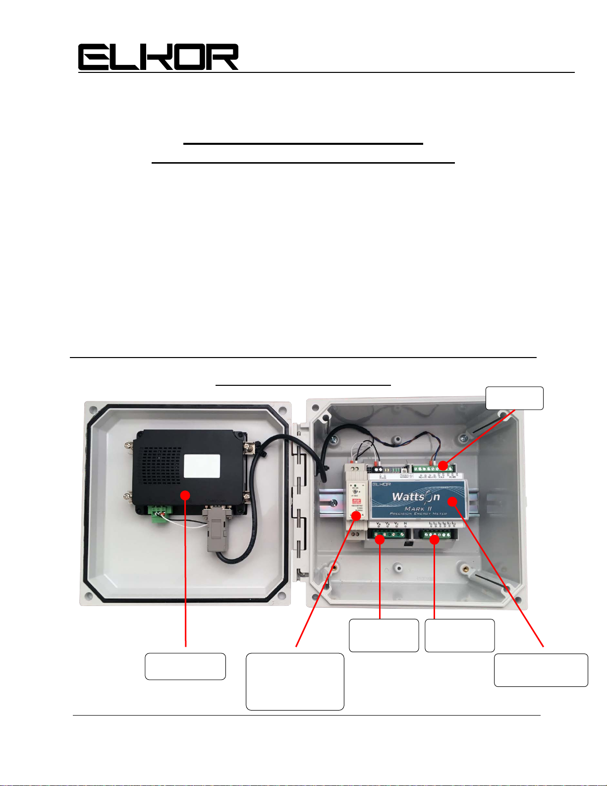
Kit Hardware Description
6 Bainard Street
London, Ontario N6P 1A8 CANADA
tel(519)652-9959 fax(519)652-1057
Technologies Inc.
Color LCD
Power Supply
120-240Vac input
24VDC output
15W
WattsOn-Mark II
Power Meter
Voltage
Inputs
Current
Inputs
Outputs

2017/07/25, rev A - 2 -
© Elkor Technologies Inc. 2016
Hardware Physical Installation
1. The WattsOn-Mark II Metering Kit (“W2KIT”) is supplied in a polycarbonate enclosure. The
enclosure carries a NEMA 4X panel
only
when ordered without the optional front panel LCD.
2. The enclosure includes mounting flanges. The flange dimensions are described in detail on the
back of the enclosure itself. The flange holes are 6” on center. The flange may be removed and
the enclosure installed directly on a panel using the flange mounting pads.
3. The enclosure should be mounted on a rigid surface. Mounting hardware must be supplied by
the installer, and be suitable for the installation surface.
4. For maximum installation flexibility, cut-outs are not provided. This is to allow the installer the
best choice of optimal location and number of wiring ingress access points. Elkor recommends
the installation of two conduits on the bottom of the enclosure. Top entry conduits should be
avoided, especially when mounting outdoors (NEMA4X version only).
5. When adding access holes, it is recommended to remove the meter and power supply. This may
be done by simply removing the two DIN rail bolts which hold the metering assembly.
6. The front panel may be removed by rotating and removing the long hinge pin. The LCD wiring
may need to be unclipped from the main enclosure body to facilitate removing the meter and
LCD as one unit.

2017/07/25, rev A - 3 -
© Elkor Technologies Inc. 2016
Electrical Installation & Wiring
Installation Considerations
Installation and maintenance of the WattsOn device must only be performed by
qualified, competent personnel who have appropriate training and experience with
electrical high voltage and current installations. The WattsOn device must be installed
in accordance with all Local and National Electrical Safety Codes.
WARNING
Failure to observe the following may result in severe injury or death:
•During normal operation of this device, hazardous voltages are present on the input terminals of
the device and throughout the connected power lines, including any potential transformers (PTs).
With their primary circuit energized, current transformers (CTs) may generate high voltage when
their secondary windings are open. Follow standard safety precautions while performing any
installation or service work (i.e. remove line fuses, short CT secondaries, etc).
•This device is not intended for protection applications.
•Do not HIPOT and/or dielectric test any of the digital outputs. Refer to this manual for the
maximum voltage level the meter can withstand.
•Do not exceed rated input signals as it may permanently damage the device.
Danger
Line voltages up to 600 VRMS may be present on the input terminals of the device and
throughout the connected line circuits during normal operation. These voltages may
cause severe injury or death. Installation and servicing must be performed only
by qualified, properly trained personnel.
Limitation of Liability
Elkor Technologies Inc. (“Elkor”) reserves the right to make changes to its products and/or their
specifications without notice. Elkor strongly recommends obtaining the latest version of the device
specifications to assure the most current information is available to the customer. Specifications and
manual are available at http://www.elkor.net
Elkor assumes no liability for applications assistance, customer’s system design, or infringement of
patents or copyrights of third parties by/or arising from the use of Elkor’s devices.
ELKOR TECHNOLOGIES INC. SHALL NOT BE LIABLE FOR CONSEQUENTIAL DAMAGES SUSTAINED IN
CONNECTION WITH ELKOR PRODUCTS, EXCEPT TO THE EXTENT PROHIBITED BY APPLICABLE LAW.
FURTHERMORE, ELKOR NEITHER ALLOWS NOR AUTHORIZES ANY OTHER PERSON TO ASSUME FOR IT
ANY SUCH OBLIGATION OR LIABILITY.
Although the information contained in this document is believed to be accurate, Elkor assumes no
responsibility for any errors which may exist in this publication.
2017/07/25, rev A - 4 -
© Elkor Technologies Inc. 2016
Power Supply
The metering KIT requires a 100-240VAC voltage for the internal power supply. This voltage may be
shared with one of the voltage input taps to the meter, however it needs to be independently wired to
the DIN rail power supply internal to the enclosure. The power supply module outputs 24VDC and is
used to power the meter and the color LCD. While it may be used to power other equipment, it is
important to consider the maximum output of the power supply (indicated on the power supply unit).
The power consumption of the WattsOn-Mark II and LCD is approximately 400mA @ 24VDC.
Voltage Inputs
Line voltage to the voltage sensing inputs (Va, Vb, Vc) should be fused. It is permissible to use existing
breakers if the distance to the breaker is close. Refer to local electrical codes. Fusing should be of
voltage of the system, and may be the smallest fusing available (typically 0.5A is reasonable). The
voltage inputs are high impedance and do not draw appreciable current (less than 250 micro-amp). The
fusing is recommended for wire protection and servicing.
Current Inputs
Current transformers should be wired to the CT inputs labeled IA1, IA2, IB1, IB2, IC1, IC2. It is
imperative that the correct CT type be used with the meter model specified.
5A CTs will destroy meters
not configured for use with them.
Shorting blocks are not required for mV, mA and RC meters & CTs. The shorting block is shown as
“optional” in the attached wiring diagrams; however they are highly recommended to be used with 5A
CTs.
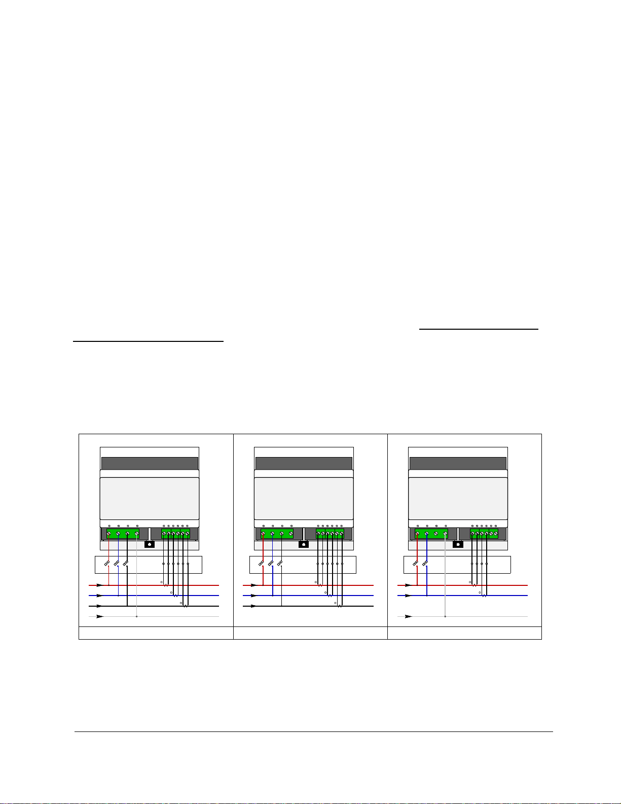
Common wiring configurations are listed below:
V VV
A AA
V VV
B BB
V VV
C CC
N NNI II
A AA1 11
I II
A AA2 22
I II
B BB1 11
I II
B BB2 22
I II
C CC1 11
I II
C CC2 22
VOLTAGE
VOLTAGE
VOLTAGE
CURRENT
CURRENT
CURRENT
H1 H1H1
H1 H1
H1 H1H1
A AA
B BB
C CC
N N
Four-Wire ("Wye") System Single ("Split") Phase SystemThree-Wire ("Delta") System

2017/07/25, rev A - 5 -
© Elkor Technologies Inc. 2016
Commissioning
Summary of steps
1. Connect RS-485 (Modbus/RTU) cabling
2. Verify DIP switch setting.
3. Power up Metering Kit
4. Configure CT / PT Ratios
5. Verify Meter Operation
Prior to powering up the meter, connect the RS-485 serial port to any external Modbus/RTU device (if
desired). The default meter serial line parameters are 9600, N, 8, 1.
By default, the Modbus address is set to “1”. This may be easily changed via the DIP switch on the
meter itself to address 1-15 (1-“F” respectively on the DIP switch). If a higher Modbus address is
required, it may be set via the LCD menu (or via software). Refer to the WattsOn-Mark II User manual
for more details.
Ensure that the meter is communicating with the display correctly. Press the “Menu” button on the
bottom of the screen to enter the menu screen.
The “Meter Uptime” and “Meter SN” fields are useful to diagnose proper communication between the
LCD and the meter as they are polled from the meter by the LCD.

2017/07/25, rev A - 6 -
© Elkor Technologies Inc. 2016
Setup menu item description
1. Brightness : The LCD screen brightness may be adjusted up/down using the arrows
2. Auto Cycle : Enable/disable the auto cycling of the screens
3. Cycle Period (s) : If Auto Cycling is enabled, duration each screen remains active before
switching to the next.
The Period is defined in seconds.
4. Meter Settings : Setup page for meter configuration (CT / PT Ratios and Modbus or BACnet
settings
5. Time Settings : Setup page for LCD date/time
6. Password Settings : Setup page for LCD Password
7. Reboot HMI : Force a reboot of the color LCD (HMI = “Human Machine Interface”)
LCD Screen Password:
The default password for the LCD panel is 1234.
The password may be changed via the “Password Settings” page. It is recommended to change the
password so that the meter settings cannot be changed via the LCD in the future. If the password is lost,
it must be recovered using a special procedure (contact Elkor for more details).
Meter Settings
To enter the “Meter Settings” menu, it is necessary to enter the password (default 1234). Click on the
“User Level Login” password field, and enter the password into the pop-up keyboard, and press “ENTER”
Once in the “Meter Settings” page, the CT and PT ratios may be modified.

2017/07/25, rev A - 7 -
© Elkor Technologies Inc. 2016
Description of items on the Meter Settings Page
1. CT Ratio: Sets the CT ratio for the specified CT
2. PT Ratio: Sets the PT ratio if the system is using PTs (typically this is not set, and left as 1:1)
3. Phase Comp: Specifies the phase compensation of the CT for higher accuracy
4. WattsOn Emulation: Enables/Disables emulation of the classic WattsOn meter.
Set the option to “ON” for any meters communicating with Westell Equipment
.
5. Modbus Settings (or BACnet): Sub menu which allows modification of serial line parameter
for Modbus/RTU or BACnet/IP.
Changing CT Ratios
To change the CT ratio, touch the CT Ratio Primary or CT Ratio Secondary Field. A keyboard will pop-up
which may be used to type the required CT ratio.
Depending on the type of CT used, the ratio should be entered as follows:
mA MeterType
CT Type
Ratio
MCTA
2500:1
MCTB
4000:1
MS160
3000:1
MS240
2000:1
MS360
2000:1
MSCT1, MSCT2,
MSCT3
7500:1
MSCT5
10500:1
MRS-75
7500:1
MRS-125
7500:1
MRS-2x5
7500:1
MRS-3x5
10000:1
RC Meter Type
CT Type
Ratio
RC-600
1000:120
5A Meter Type
CT Type
Ratio
XYZ : 5A
XYZ:5
2017/07/25, rev A - 8 -
© Elkor Technologies Inc. 2016
Changing PT Ratios
To change the PT ratio, follow the same steps as per “Changing CT Ratios”. In most cases PTs are not
required, however, if used, the PT ratio must be entered to obtain correct readings.
Phase Compensation
All Elkor mA output CTs are quantified for their relative phase shift characteristic. This metric (which is
specific to every CT) is marked on the CT label. In most cases, the phase shift does not need to be
entered, however for ultimate accuracy, it should be applied so that the meter can compensate for the
phase shift performance of the current transformer.
The WattsOn-Mark II allows for CT Ratio and Phase shift values on a per-channel basis, however the LCD
only allows entry of the parameters on a global level. In this case, it is suggested to use the average
value, since they tend to be fairly uniform among a CT model.
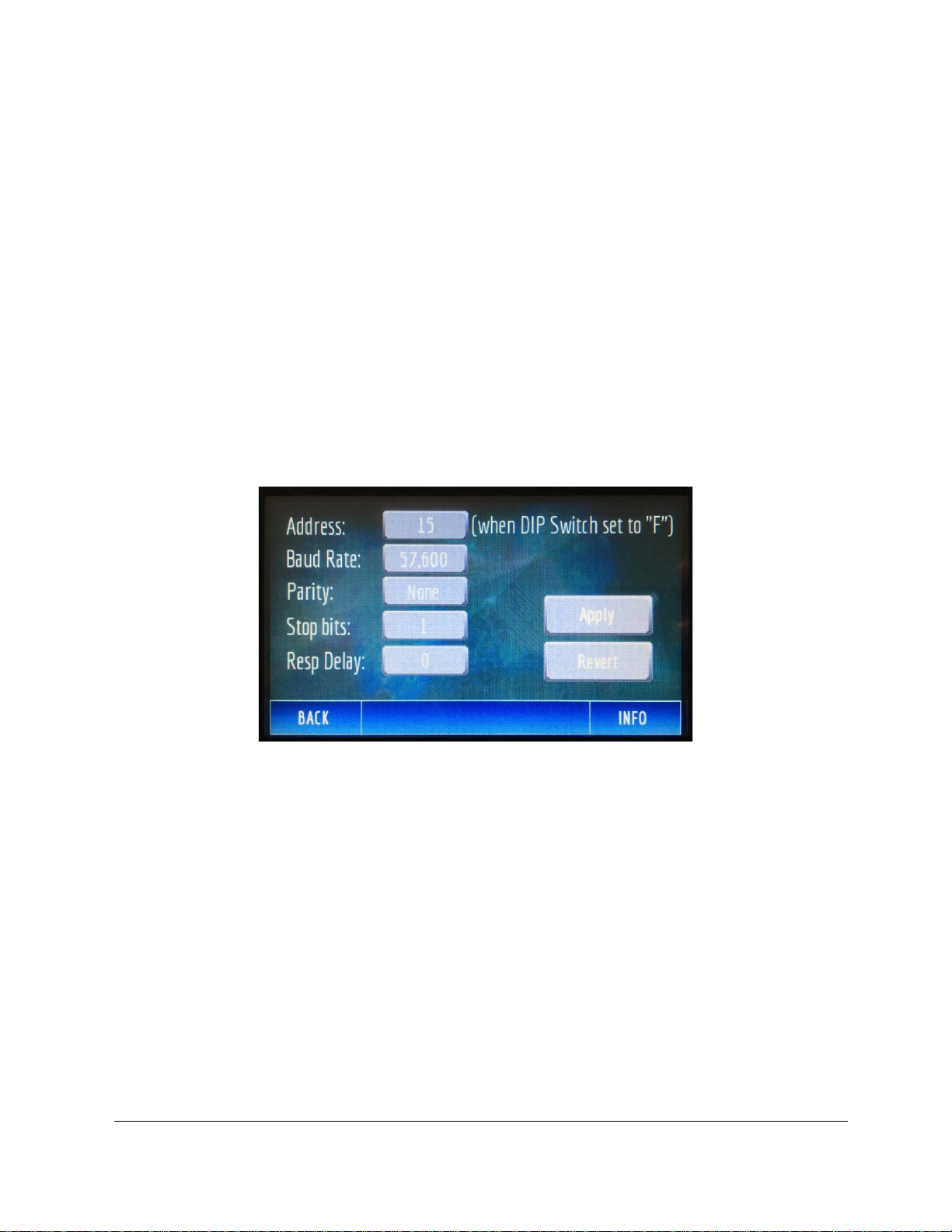
Modbus Settings
The RS-485 Modbus/RTU settings may be changed from this menu:
Description of items on the Modbus Settings:
1. Address: Specifies the Modbus address that is used when the DIP switch on the meter is set to
“F”. This setting is useful to define Modbus Addresses higher than 15. When the DIP switch is
set to a value other than “F” the address of the meter will be the DIP switch address. This field
does not show the current DIP switch setting.
2. Baud Rate, Parity, Stop Bits: Changes the serial communications parameters. These
parameters should match all of the other devices on the RS-485 bus.
3. Resp Delay: The amount of time (in milliseconds) that the meter should delay after receiving a
query. Refer to the WattsOn-Mark II user manual for more details.
After a change is made, the “Apply” button must be pressed to enact the changes.

2017/07/25, rev A - 9 -
© Elkor Technologies Inc. 2016
Verify Meter Operation
Once the meter configuration has been set it is important to verify the meter installation and operation
prior to leaving the site.
Navigate the LCD screens to the table view. This view shows all real-time values in table form:
In this case, we can observe the following:
1. Vl-n: (voltage line-to-netural) values are within the correct range we would expect
2. Vl-l: (voltage line-to-line) values are correct and unique. These fields show Vab, Vbc, and Vac
respectively. It is important, as in may be the case where a single voltage is tapped twice, in
which case one of the values would show “zero”
3. V. Angle: shows the voltage angle between phases A-B, B-C, and A-C respectively.
4. Current: shows the instantaneous current. It may be useful to check the measured value with a
clamp-on meter at the same spot where the CT is installed.
5. kW: This number should be the product of Vl-n * Current * PF for the respective phase. If this
value is unexpectedly low, check the current values, and the power factor (see below). If the
value is negative and the power factor is correct, it may indicate reversed CT or swapped CT
polarity into the meter.
6. kVAR, kVA: These numbers will depend on the type of load. kVA should be the mathematical
product of Vl-n * Current for each respective phase
7. PF: Shows the power factor for each phase. Typically the value should be about 0.900-1.000,
(regardless of sign). If the (absolute) value is significantly low, it is possible that the CTs are not
installed correctly (see next paragraph).
If the kW and/or PF are low, it is typically indicative of a common wiring mistake: mis-matching CT and
voltage channels. The easiest diagnostic is to visually trace and confirm that the CT wired into IA1/IA2 is
mounted on the phase which connects to Va. The same rationale should follow for phase B and C
respectively. If it is impractical to do this, Elkor provides an online “phase-swap” calculator which allows
the user to simulate swapping CT phases to observe the effect.
Other manuals for WattsOn-Mark II
1
Other ELKOR Measuring Instrument manuals


