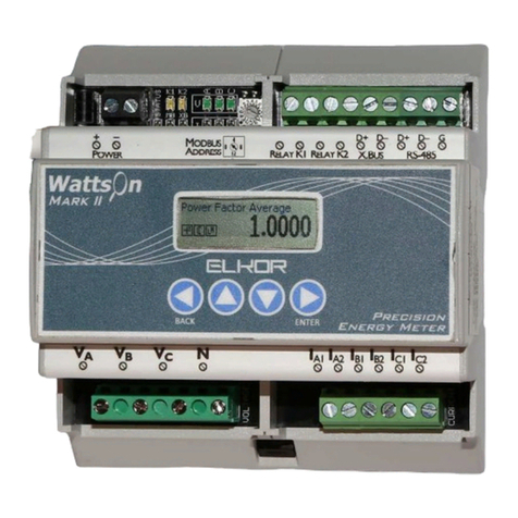
ELKOR WattsOn-MCM Operation manual

Technologies Inc.
WattsOn-MCM Installation & User Guide

ELKOR TECHNOLOGIES INC. - Page 2 - MCM –USER MANUAL
Limitation of Liability
Elkor Technologies Inc. (“Elkor”) reserves the right to make changes to its products and/or their specifications without
notice. Elkor strongly recommends obtaining the latest version of the device specifications to assure the most current
information is available to the customer. Specifications and manuals are available at http://www.elkor.net
Elkor assumes no liability for applications assistance, customer’s system design, or infringement of patents or copyrights
of third parties by/or arising from the use of Elkor’s devices.
ELKOR TECHNOLOGIES INC. SHALL NOT BE LIABLE FOR CONSEQUENTIAL DAMAGES SUSTAINED IN CONNECTION
WITH ELKOR’S PRODUCTS, EXCEPT TO THE EXTENT PROHIBITED BY APPLICABLE LAW. FURTHERMORE, ELKOR
NEITHER ALLOWS NOR AUTHORIZES ANY OTHER PERSON TO ASSUME FOR IT ANY SUCH OBLIGATION OR LIABILITY.
Although the information contained in this document is believed to be accurate, Elkor assumes no responsibility for any
errors which may exist in this publication.

ELKOR TECHNOLOGIES INC. - Page 3 - MCM –USER MANUAL
TABLE OF CONTENTS
1. Introduction .............................................................................................................................................. 5
1.1. Documentation .................................................................................................................................................5
1.2. Disclosure.........................................................................................................................................................5
1.3. Product Description ...........................................................................................................................................5
1.4. Features...........................................................................................................................................................5
1.5. Visual Guide .....................................................................................................................................................6
1.6. Connectors .......................................................................................................................................................7
1.7. Main Indicators .................................................................................................................................................7
1.8. Node Indicators ................................................................................................................................................7
1.9. Voltage Isolator Indicators.................................................................................................................................7
1.10. Status Indicator Codes ....................................................................................................................................8
1.11. Buttons ..........................................................................................................................................................9
1.12. Default Settings ..............................................................................................................................................9
2. Installation.............................................................................................................................................. 10
2.1. Overall Procedure ...........................................................................................................................................10
2.2. Communication Setup .....................................................................................................................................10
2.3. Network Discovery and Network Settings .........................................................................................................11
2.4. Enclosure Mounting.........................................................................................................................................13
2.5. Node Installation.............................................................................................................................................13
2.6. Current Inputs ................................................................................................................................................14
2.7. Voltage Inputs ................................................................................................................................................14
2.8. Power Supply..................................................................................................................................................14
3. The Web Interface .................................................................................................................................. 15
3.1. Accessing the Web Interface............................................................................................................................15
3.2. Node Setup ....................................................................................................................................................15
3.3. Monitor Page ..................................................................................................................................................16
3.4. User Registers Page ........................................................................................................................................16
3.5. Posting Status.................................................................................................................................................17
3.6. Information Page ............................................................................................................................................18
3.7. Diagnostics Page.............................................................................................................................................18
3.8. Filesystem Page ..............................................................................................................................................18
3.9. Network Page .................................................................................................................................................19
3.10. System Page.................................................................................................................................................19
3.11. Changing the Administrator Password ............................................................................................................19
3.12. Reading Registers .........................................................................................................................................19
3.13. Posting Data to the Elkor Cloud......................................................................................................................19
3.14. Posting Data to your own Web Server (Advanced Feature) ..............................................................................20
3.15. Customizing the Web Posting Format (Advanced Feature) ...............................................................................21
4. The Modbus Protocol ..............................................................................................................................23
4.1. Protocol Overview ...........................................................................................................................................23
4.2. Basic Information Registers .............................................................................................................................26
4.3. Universal Card Parameters...............................................................................................................................27
4.4. Node Electrical Parameters ..............................................................................................................................28
4.5. Voltage Parameters.........................................................................................................................................29
5. Upgrades and Other Procedures ............................................................................................................. 30
5.1. Adding a New Node ........................................................................................................................................30
5.2. Replacing a Node ............................................................................................................................................30
5.3. Reconfiguring a Node ......................................................................................................................................30
5.4. Removing a Previously Configured Node...........................................................................................................30
5.5. Moving a Node to a New Slot...........................................................................................................................30
5.6. Factory Reset .................................................................................................................................................30
5.7. Changing the Firmware ...................................................................................................................................30
6. Appendix A, Modbus Protocol Details ..................................................................................................... 32
6.1. Modbus Frames on RS-485 Networks ...............................................................................................................32
6.2. Modbus Frames on Ethernet/Wi-Fi Networks.....................................................................................................32

ELKOR TECHNOLOGIES INC. - Page 4 - MCM –USER MANUAL
6.3. Cyclic Redundancy Checksum ..........................................................................................................................32
6.4. Read Holding Registers ...................................................................................................................................33
6.5. Read Input Registers.......................................................................................................................................33
6.6. Write Single Register.......................................................................................................................................33
6.7. Write Multiple Registers...................................................................................................................................33
6.8. Mask Write Register ........................................................................................................................................34
6.9. Read/Write Multiple Registers ..........................................................................................................................34
6.10. Diagnostic Functions .....................................................................................................................................35
6.11. Get Comm Event Counter ..............................................................................................................................37
6.12. Report Slave ID.............................................................................................................................................37
7. Appendix B, CT Wiring ............................................................................................................................ 39
7.1. Single Phase Installation..................................................................................................................................39
7.2. Two / Split Phase Installation...........................................................................................................................40
7.3. Three Phase Installation ..................................................................................................................................41

ELKOR TECHNOLOGIES INC. - Page 5 - MCM –USER MANUAL
1. INTRODUCTION
1.1. Documentation
This document was last revised in December 2020 (rev. 2).
Revision History
March 2020
Rev. 1
Initial revision
December 2020
Rev. 2
Corrected 2.6 to refer to "upper"/"lower" ports instead of "left"/"right"; added Appendix B
1.2. Disclosure
This publication contains information proprietary to Elkor Technologies Inc. No part of this publication may be reproduced,
in any form, without prior written consent from Elkor Technologies Inc.
1.3. Product Description
The WattsOn-MCM is a modular, internet-accessible metering solution for up to 60 independent circuits. It houses
between one and twenty metering "nodes", which measure three independent circuits each. The device measures Volts,
Amps, Real Power, Voltage Angle, Power Factor and Frequency, and Watt-Hours. These parameters can be read per-
channel, or aggregated into user-defined groups.
The WattsOn-MCM may be purchased with as few or as many nodes as needed, and additional cards can be added at a
later date if additional circuits are needed. Nodes are "hot-pluggable", meaning they can be added or removed without
powering off the device, ensuring metering is not interrupted.
It provides a dynamic AJAX-enabled web-interface to configure the device and to display readings, and can also send its
data to a web server via HTTP POST at regular intervals, using a highly configurable template-based format. The
WattsOn-MCM will store a backlog of data in the event of short, temporary network outages to ensure any post
information is not lost.
The unit accepts up to 600V (line-to-line) directly without needing potential transformers. It may be configured for use
with 333mV output CTs or mA output CTs (such as Elkor’s "safe" mA split and solid core CTs).
The WattsOn-MCM supports DHCP. A Windows® utility is used to detect and configure the network parameters from a
Windows PC. In addition, the web interface allows for full device configuration.
For developers, custom web pages may be uploaded onto the device to create custom, highly integrated user interfaces.
1.4. Features
The following bullet points summarize the WattsOn-MCM’s features:
•Metering for 3 to 60 independent circuits.
•Expandable after installation
•Uninterrupted metering: circuits can be added while powered
•Serial, Ethernet, or Wi-Fi communication
•Real-Time monitoring via web interface
•Highly customizable data posting via HTTP
•Communication via Modbus TCP and Modbus RTU
•Support for HTTP and HTTPS/SSL web posting
•Support for DHCP and static IP addresses
•Upgradable firmware

ELKOR TECHNOLOGIES INC. - Page 6 - MCM –USER MANUAL
1.5. Visual Guide
The following image illustrates the different components and ports of the WattsOn-MCM, which are referred to in this
section and throughout the document.
A
B
C
A
B
C
A
B
C
A
B
C
A
B
C
A
B
C
A
B
C
A
B
C
A
B
C
A
B
C
A
B
C
A
B
C
A
B
C
A
B
C
A
B
C
A
B
C
A
B
C
A
B
C
A
B
C
A
B
C
VAVBVCN
1 11
10 20
9 19
8 18
7 17
6 16
5 15
4 14
3 13
2 12
Power
Supply
100~240
Vac
to
24VDC
ETHERNET
ACTIVITY SERIALRESET REBOOTFAULTSTATUS
MB
24VDC
100mA
OUTPUT
AUX
+ ++
- --
HMI Interface
100~240
Vac
+ -
24VDC
Metering
Node
Metering
Node
PCI Slot
Power
Supply
MCM-V
Voltage
Isolator
WMC-COMM
Master Module
Main
Indicators

ELKOR TECHNOLOGIES INC. - Page 7 - MCM –USER MANUAL
1.6. Connectors
Port
Description
N, L (Power Supply, bottom-left)
Neutral and 100-240V power supply inputs
24VDC Input (middle)
DC voltage input from Power Supply
MB (top-right)
Two-wire RS-485 serial connection for Modbus RTU communication
Aux (top-right)
Auxiliary Two-wire RS-485 serial connection for direction Modbus RTU communication
with individual cards, intended for debugging and WattsOn compatibility purposes
only
Ethernet (top)
RJ-45 (8P8C) 10/100mbit half/full duplex Ethernet (auto-sensing) connection
A, B, C (MCM Voltage Isolator,
bottom-right)
Voltage channel inputs
N (MCM Voltage Isolator,
bottom-right)
Neutral voltage input
A, B, C (left and right side)
CT channel inputs
PCI Slots 1 to 20
Metering node slot
1.7. Main Indicators
Name
Location
Color
Description
Status
Center
Green
Indicates the status of the device's network connectivity; see the
following table for a detailed description of possible states.
Activity
Center
Green
Indicates communication between the master device and the
individual nodes.
Fault
Center
Red
Indicates a problem. See the following table for a detailed description
of possible states.
Serial
Bottom-left
Red/Green
Indicates activity over the "MB" RS-485 port. Red indicates data
reception, and green indicates data transmission. Red flashes without
corresponding green flashes may indicate a misconfiguration of the
serial port parameters, if there are no other devices on the bus.
1.8. Node Indicators
Name
Location
Color
Description
Status
Left
Red/Green
Indicates the status of the node. Green indicates proper functioning,
flashing green partial functioning (such as when a firmware update is
taking place), and red indicates a problem (such as when the node is
physically damaged or its firmware is corrupt).
ACT
Right
Green
Indicates communication between the master device and the
individual nodes.
AUX
Center-Right
Red/Green
Indicates activity over the "AUX" RS-485 port. Red indicates data
reception, and green indicates data transmission. All nodes on the bus
receive all messages (flashing red), but only a single node will respond
(flash green) at a time.
1.9. Voltage Isolator Indicators
Name
Location
Color
Description
Status
Center-Right
Red/Green
Indicates the status of the module. Green indicates proper functioning,
flashing green partial functioning (such as when a firmware update is
taking place), and red indicates a problem (such as when the node is
physically damaged or its firmware is corrupt).
Comm
Right
Green
Indicates communication between the master device and the voltage
isolator module.
Va, Vb,
Vc
Bottom
Red/Green
Indicates a voltage on the voltage channel inputs above a minimum
threshold (5% of the full-scale voltage).

ELKOR TECHNOLOGIES INC. - Page 8 - MCM –USER MANUAL
1.10. Status Indicator Codes
Code
Description
Status solid green, with fault off indicates that the device is connected via
Ethernet
Status 95% green, 5% off, with fault off indicates that the device is
connected via Wi-Fi.
Status 50% green, 50% off, with fault off indicates that the device is in
access-point mode. Connect to the device with a mobile phone or other
wireless device to configure a wireless network, or plug in an Ethernet cable.
One periodic red flash indicates that networking is not working properly, but
the device is otherwise functional. The RS-485 port may still be used in this
state.
Ensure that the Ethernet cable is connected, if used, and that there is a
networked path from the WattsOn-MCM to the DHCP server (usually the
router). If Wi-Fi is used, ensure that the wireless network is up and running
and that the SSID and Password last programmed into the device are
correct.
Two periodic red flashes indicates that the last web post has failed. This may
be temporary, or indicate a configuration problem with the WattsOn-MCM or
the server.
Fault solid red with status flashing indicates that a fault with one or more of
the installed nodes. A node may have failed, or may have been unexpectedly
removed. The other non-faulted nodes continue to function normally.
The Web Interface will show details about which node has faulted, if
possible. The status LED on the faulted card may also be blinking green and
red, or be off. Try re-seating this card in its PCI slot, or replacing it.
Fault solid red with status off indicates a fault that prevents the entire
WattsOn-MCM from metering. The web interface is normally still functional,
though metering data cannot be read in this state. This can happen when
communication with the nodes has failed, or the voltage cannot be read.
Ensure that the WattsOn-MCM-V is on and its status LED is green, and that
the status LEDs of all of the installed cards are solid green. Try removing or
re-seating any device with an off, red, or blinking green/red status LED. If all
are green, try removing each card, one at a time, and waiting 15 seconds
each time to see if the fault light clears; if the fault clears in this way, try re-
seating or replacing that node.
Repeated red flashes in a "…---…" pattern with status off indicate that the
WattsOn-MCM master device has suffered a fault is not functioning. The
firmware may be corrupt, or the hardware may be damaged.
FAULT
FAULT
STATUS
STATUS
FAULT
FAULT
STATUS
FAULT
STATUS
STATUS
STATUS
STATUS
STATUS
STATUS

ELKOR TECHNOLOGIES INC. - Page 9 - MCM –USER MANUAL
1.11. Buttons
Name
Location
Action
Description
RESET
Center-left
Hold for 10 seconds to restore factory default settings for the device.
REBOOT
Center-right
Press to power-cycle the device.
1.12. Default Settings
Ethernet
IP Address
Automatically obtained via DHCP if available;
Automatically configured via AutoIP if DHCP is unavailable
Subnet Mask
Default Gateway
Passwords
Username
admin
Password (default)
admin
RS-485/Modbus
Serial mode
Modbus/RTU
Baud rate
115200
Parity
None
Data bits
8
Stop bits
1

ELKOR TECHNOLOGIES INC. - Page 10 - MCM –USER MANUAL
2. INSTALLATION
2.1. Overall Procedure
When working with the WattsOn-MCM device for the first time, especially if Wi-Fi is required, it is recommended to first
setup and verify communication between the WattsOn-MCM and a PC or mobile device at a convenient location, before
live voltages and current transformers are connected in their intended, final location.
See the visual guide in the previous section (p. 6) to locate ports and components. The following outlines the overall
procedure. A section and page number following each step indicates where details can be found for each step.
1. Setup and test communication port(s) [see 2.2-2.3, p. 10-11]
−Three options exist: Ethernet, Wi-Fi, or RS-485 serial
−Configuring Wi-Fi is simpler if an Ethernet cable can be used temporarily to program the Wi-Fi settings,
though this is not required. If unavailable, a mobile device or PC with Wi-Fi capability can also be used.
−Serial can be used simultaneously with Ethernet/Wi-Fi. Ethernet and Wi-Fi cannot be used simultaneously.
2. Setup communication software [see 3, The Web Interface,p. 15 or 4, The Modbus Protocol, p. 23]
−Three options exist: the Web Interface or Modbus TCP (for Ethernet/Wi-Fi), or Modbus RTU (for serial).
−For the Web Interface, any up-to-date standards-compliant browser on PC or mobile devices can be used.
−For Modbus TCP/RTU, Elkor's free tool Modbus Commander, or software from other vendors, can be
used.
−Initial node setup can only be done using the Web Interface. Modbus is strictly read-only on the
WattsOn-MCM.
3. Mount in intended location [see 2.4, p. 13]
4. Install metering nodes into PCI slots [see 2.5, p. 13]
−Nodes can also be added later, even while the device is powered on.
5. Connect current transformers (CTs) to the terminal blocks corresponding to the installed nodes. [see 2.6, p.14]
−CT polarity is important for some node types.
6. Connect voltage inputs to the terminal blocks on the WattsOn-MCM-V, observing relevant safety practices. [see
2.7, p. 14]
7. Connect power to the power supply N and L inputs, observing relevant safety procedures. [see 2.8, p. 14]
8. Setup Nodes using the Web Interface [see 3.1-3.2, p. 15]
2.2. Communication Setup
There are three options for communicating with the WattsOn-MCM: using the RS-485 serial port (with the Modbus RTU
protocol), using the Ethernet port (with either the web interface, or the Modbus TCP protocol), or using Wi-Fi (with the
same options as with the Ethernet port). Depending on which port you would like to use, following the instructions in the
following sections. If desired, the RS-485 serial port can be used simultaneously with either Ethernet or Wi-Fi; however,
Ethernet and Wi-Fi cannot be used at the same time.
Note that Wi-Fi mode will not activate if an Ethernet cable is connected to the device.
2.2.1. RS-485 Port
Connect RS-485 wires to the D+ / D–terminal on the top-right RS-485 port, labelled "MB", of the WattsOn-MCM. Connect
the other end to a Modbus master device (with D+ to D+, D–to D–), or to a PC via a USB-to-RS485 converter cable.
The RS-485 port comes factory-programmed with the indicated settings below. The baud rate, parity, and stop bit
settings can be changed via the Web Interface; see Section 0,
The Web Interface (p. 15).

ELKOR TECHNOLOGIES INC. - Page 11 - MCM –USER MANUAL
Parameter
Default Value
Device Address
Modbus Address 1
Baud rate
115200 bps
Parity
None
Data bits
8
Stop bits
1
2.2.2. Ethernet Port
Connect an Ethernet cable to the top RJ-45 (8P8C) jack. Connect the other end to your router, switch, hub, or directly to
a PC. See the following section, Network Discovery, for details finding its IP address and viewing the Web Interface.
2.2.3. Wi-Fi
Note that Wi-Fi is only available when the Ethernet port is disconnected. To program the device with the settings
for your wireless network, there are two options:
(a) connecting to the WattsOn-MCM with an Ethernet port first, or
(b) connecting to the WattsOn-MCM over Wi-Fi via a mobile phone or PC with Wi-Fi support.
The first method is considerably simpler, if possible at your location.
For method (a), connect an Ethernet cable to the top RJ-45 (8P8C) jack. Connect the other end to your router, switch,
hub, or directly to a PC. See the following section, Network Discovery, for details finding its IP address and configuring
Wi-Fi parameters.
For method (b), perform the following steps.
1. Connect a Wi-Fi enabled device, such as a mobile phone or a PC, to the wireless network created by the WattsOn-
MCM. This network will have a name, or SSID, beginning with "MCM-" followed by the final four characters in its
MAC address.
−The mobile device or PC may issue a warning that the internet is not available on this network; this is
normal.
2. Once connected, open a browser and direct it to the address http://192.168.1.1, which will load the device's Web
Interface.
−If you have already installed one or more metering new nodes, it may prompt you to configure the cards,
which can safely be skipped temporarily by clicking "Finish Later."
−Fore details about the device's Web Interface, see Section 0,
−The Web Interface (p. 15).
3. Click on the "Network" menu item under the Gateway heading to open up the network settings.
−On a small screen device, you may need to open the menu by first clicking on the menu button, ☰, in
the top right.
4. Fill in the boxes labelled "Wifi SSID" and "Wifi Password" with the settings for your wireless network, and click
"Submit". The device will reboot, and will attempt to connect with the given settings.
5. If the settings are incorrect, or the procedure cannot be performed with the available devices, try method (a), or
clear the above settings and try again with this method by performing a Factory Reset (see 5.6, Factory Reset
(p. 30).
2.3. Network Discovery and Network Settings
By default, the WattsOn-MCM is configured to automatically obtain its IP address via DHCP if available, and with AutoIP
otherwise. If you are the network administrator, you may be able to determine the device’s IP address by consulting your
router’s user interface. Otherwise, you can use the Elkor Network Device Finder utility available for the Windows
operating system.
2.3.1. Network Discovery with the Elkor Network Device Finder
The Elkor Network Device Finder is a stand-alone program that runs on Microsoft Windows operating systems to assist in
discovering any WattsOn-MCM devices on the local area network when their IP addresses are not known. You can
download the utility from Elkor’s website, at http://www.elkor.net/bin/finder.exe.

ELKOR TECHNOLOGIES INC. - Page 12 - MCM –USER MANUAL
To run the utility, simply double-click on the downloaded executable. The executable is “portable”–it does not require an
installer, making it easy to take with you on a USB key or similar device if it must be used in a field location that does not
have full internet access.
The utility will automatically search for any Elkor devices present on the network. If the device does not show up within a
few seconds, you can have the program send subsequent broadcasts by clicking the
Find
button.
2.3.2. IP Configuration
If desired, the IP address, address assignment method can be changed, or wireless network settings can be assigned.
Once you have found the WattsOn-MCM with the Elkor Network Device Finder (see the previous subsection), you can
double-click on it to enter the IP address configuration dialog box.
You can choose to either use a static IP configuration (i.e. one that you provide manually), or the Dynamic Host
Configuration Protocol (DHCP, a router or other device on the network automatically assigns the device an IP
configuration when it starts up). By default, the WattsOn-MCM uses DHCP. If it has been configured to use a static IP
configuration, you can set it back to DHCP by clicking the
DHCP
radio button and clicking
Apply
.
To enter a static IP configuration, click the
Static
radio button, and the other fields will be available for editing. You can
enter an IP address, subnet mask, default gateway, primary and secondary DNS servers. If you are unsure as to how to
configure IP address settings, consult your network administrator. If a static IP address is chosen, the network
administrator must manually ensure that no other devices on the network are using this IP address, and that the router
or other DHCP server does not include this IP address in its DHCP address pool.
The default gateway, primary and secondary DNS server IP addresses are either supplied by your internet service
provider, or the same as the address of the device you use to connect to the network (i.e. your router). The secondary
DNS server is optional, and may be left blank.
To configure Wi-Fi mode, enter an SSID and Password in the WiFi Settings (optional) area.
Note that Wi-Fi mode will not activate if an Ethernet cable is connected to the device.
A valid username (always “admin” for the WattsOn-MCM) and password (default: “admin”) are required to apply the
changes.

ELKOR TECHNOLOGIES INC. - Page 13 - MCM –USER MANUAL
2.4. Enclosure Mounting
The WattsOn-MCM is intended to be installed indoors. While the enclosure is rated at NEMA4X, if equipped with the front
panel HMI display, the enclosure is de-rated to NEMA1. Additionally, the enclosure openings must be properly sealed
with rated grommets, glands or covers (not included).
The enclosure is designed for wall mounting using the attached feet. The below diagram shows the dimensions for the
panel mounting feet.
2.5. Node Installation
Each node can meter up to three independent circuits, and up to 20 can be installed in a single WattsOn-MCM, giving a
total of 60 independent circuits. Each node plugs in to one of the 20 PCI slots on the WattsOn-MCM, numbered 1 through
10 on the left side, and 11 through 20 on the right side. The nodes do not need to be installed in any particular order –
any node can be installed into any slot, left or right, according to convenience.

ELKOR TECHNOLOGIES INC. - Page 14 - MCM –USER MANUAL
Nodes are "hot-pluggable," meaning that they can be installed or removed even while the device is powered, allowing for
metering to continue un-interrupted even when the configuration is changed.
Each node corresponds to three current inputs. Each current input must be paired with a voltage input during setup. Any
current channel on any node can be paired with any voltage channel.
2.6. Current Inputs
Standard wiring principles for electricity meters apply to the WattsOn-MCM, as for any other electricity meter.The polarity
of interfacing transformers must be observed. The upper terminal of each current input connector is always associated
with the 'X1' wire of the coresponding CT, with the lower terminal corresponding with the 'X2' wire. Please refer to
Appendix B, CT Wiring (p. 39) for details.
All mV and mA CTs must be wired independently to the corresponding current inputs (two wires from each CT without
shunts or jumpers). mA and mV CTs must
NOT
be grounded, or interconnected with each other (or any other
components) in any way.
A CT shorting mechanism is not required for mV and Elkor mA style CTs, since these are voltage clamped, however
appropriate protection (fuse or breaker) for input line voltages is required.
2.7. Voltage Inputs
The four input terminals on the bottom of the WattsOn-MCM-V, on the bottom-right of the WattsOn-MCM, are voltage
inputs, with the rightmost terminal being the neutral line. Line-to-line voltages of up to 600V may be present on these
lines, so proper electrical safety procedures should be followed during installation and maintenance according to local
codes.
Line voltages of up to 600V line-to-lne on the WattsOn-MCM-V terminals are isolated from the rest of the WattsOn-MCM's
components, and from the output ports.
2.7.1. Fusing of Voltage Sensing Inputs
The input voltage lines should be protected as per electrical code requirements. This is also good practice to facilitate an
easy disconnect means for servicing the meter. In some cases, the voltage may be tapped off of existing fuses or
breakers. If this is not possible, Elkor recommends a 1A or lower fuse (fast acting) for protection of the installation wiring.
The WattsOn-MCM voltage inputs are high impedance (> 1.5MΩ) and draw negligible current (less than 0.3mA max).
2.8. Power Supply
The WattsOn-MCM is powered by a 10W, 100-240VAC (input) power supply which is DIN rail mounted next to the isolator.
This power supply outputs 24VDC to the motherboard, from which each component is powered. The power supply also
provides 4kVAC isolation between the input (100-240VAC) and the output (24VDC). While this DIN rail power supply may
be replaced with an external 24VDC source, considerations for grounding and power requirements should be observed.
The power supply inputs may be shared with the metering lines provided that the measurement voltage is within the 100-
240VAC specification. If there is no voltage within the 100-240VAC range available at the installation location, contact
Elkor Technologies Inc. for options.

ELKOR TECHNOLOGIES INC. - Page 15 - MCM –USER MANUAL
3. THE WEB INTERFACE
3.1. Accessing the Web Interface
To access the web interface for the WattsOn-MCM, open a web browser and direct it to the device’s IP address. (To
discover the device’s IP address for the first time, refer to Section 2.3Network Discovery and Network Settings, p.
11). We recommend using Mozilla Firefox or Google Chrome to access the web interface, but other standards-compliant
web browsers should work fine.
Figure 1. Accessing the Web Interface
The web interface provides a number of status indicators and configuration features.
Note —Default Password: By default, the configuration pages are protected with a password.
The first time you access the web interface, the default username and password will be
admin
and
admin
. This password can be changed, if desired; see 3.11, Changing the
Administrator Password (p. 19).
On large screens, the left-hand side of the web interface contains the different configuration pages available. They are
divided into two sections, Connected Devices, which contains features related to the attached devices, and Gateway,
which contains features that pertain to the Ethernet/Wi-Fi gateway itself. The center of the interface shows the current
configuration/status page –Information, by default. On small screens, the menu opens via a button at the top-right of
the screen, which is shown with this symbol: ☰
3.2. Node Setup
The first time the Web Interface is accessed, or after any new nodes are added
or removed, the Configuration Wizard is displayed. If there were already some
nodes installed previously, only the new or replaced nodes will be shown for
configuration.
To access the wizard at any other time, or to re-configure previously-
configured nodes, click on the "Card Setup Wizard" button in the menu.
Click "Next" to start configuring the cards. The web interface may issue a
prompt for a username and password (the default is "admin" and "admin" on a
new WattsOn-MCM).
There are three steps for configuring each node:
1. Adding a name and note to each of its three channels (optional)
2. Setting the CT ratio, and depending on the CT type, its phase compensation
3. Pairing each current channel to a voltage channel
Click the "Next" button to move through each step on each node. Some or all of the nodes can be skipped with the "Skip
Card" button, and it can be configured later. All remaining cards can be skipped with the "Skip to End" button. To skip

ELKOR TECHNOLOGIES INC. - Page 16 - MCM –USER MANUAL
configuration entirely, click "Finish Later," and the web interface will issue a prompt to configure the cards the next time it
is visited.
After each "Next" button, the configuration is saved, so that it can be returned to at a later time. A node will continue to
appear in the configuration wizard until the entire process has been completed, however previously entered values are
saved.
3.2.1. Channel Names and Notes
For each channel, you can add a 16-character name and short note, for ease of identification later. This is entirely
optional.
3.2.2. CT Ratios and Phase Compensation Values
For each channel, a CT ratio must be entered. Either find the CT model in the
drop-down list (which will fill in the ratio automatically), or enter the ratio
manually in the box. This information is generally found on the CT itself or in the
CT's documentation.
Some CTs have a phase offset, which must be compensated for to provide
accurate power and energy readings. Enter a phase compensation value in the
final box, in degrees, with a precision of up to one hundredth of a degree.
3.2.3. Matching Current and Voltage Channels
Each current channel must be paired with a voltage channel in order to measure
power and energy. Any current channel can be paired with any voltage channel
—all channels on a card can use the same or different voltage channels.
To assist in preventing mistakes, the amps and volts of each current and voltage
channel (respectively) are displayed, as well as the watts and power factor of the
currently selected combination. Very broadly speaking, the correct combination
usually has a relatively high power factor when compared to the incorrect
combination, though this is just a generalization.
If a mistake was made, it can be corrected by reconfiguring the card at any time,
however, previously accumulated energy measurements will not be valid. It is
recommended to reset the energy accumulation in this case; an option to do so
will be presented as the final step of the configuration process.
3.2.4. Resetting Energy Accumulation
At the end of the configuration process, the wizard will offer to reset the accumulated energy for each of the nodes. This
is recommended so that all accumulated readings begin from exactly the same start time. However, this is not required,
as energy readings are normally only used differentially.
3.3. Monitor Page
The monitor page displays many of the readings that the WattsOn-MCM collects. Hovering the mouse over a channel
shows details.
3.4. User Registers Page
This page allows you to configure custom data points to display. These data points can include any reading that the
WattsOn-MCM provides, or it can be a sum, average, or other mathematical combination of any of those points. For
example, it may be convenient to display the total current in channels 1 through 5, or the average power consumption of
channels 2, 4, and 6.
To add a new data point, or edit existing data points, click the button in the lower-right of the page to unlock the page
for editing. Once unlocked, you can perform the following actions:

ELKOR TECHNOLOGIES INC. - Page 17 - MCM –USER MANUAL
3.4.1. Adding a New Data Point
1. Click the "+" button to begin adding a new data point.
2. Give the point a name by filling in "Point Name".
3. The formula determines which data will be displayed. To add a new data point to the formula, select its data type,
offset, and count from the "MB Point Generator" box at the bottom. The information for these boxes can be
found in Section 4, The Modbus Protocol (p. 23), which contains a listing for all parameters measured by the
WattsOn-MCM.
For example, the register 0x2003 is a 16-bit register called the "Debug Registers", which always reads as
12345. To add this register, enter "unsigned short (16-bit)", "0x2003", and "1" into the "MB Point Generator"
boxes and click "Add to Formula". The formula will now read "$ushort(0x2003)".
4. To add math operations, you can edit the formula to include the character "+", "-", "*", and "/" for addition,
subtraction, multiplication, and division, respectively. Brackets, "(" and ")", can also be added to indicate order of
operations.
For example, to double the register we added above, the formula would be "$ushort(0x2003) * 2"
5. Multiple registers can be added using the MB Point Generator, for example, to add two or more registers together.
6. When finished, click "Apply".
7. For details on the formula language used by this device, see the separate document, ETPORT API.
3.4.2. Remove an Existing Point
Click the icon resembling a trash can to delete a data point.
3.4.3. Modify an Existing Point
Click on the icon resembling a gear to bring up the formula window. Follow the instructions for Adding a New Data Point
from #2 to modify the data point.
3.5. Posting Status
Below the Connection Status box is the Posting Status box. If the Web
Posting feature is enabled, this box shows the status of the most recent
web post that has been made since the device was powered on. It will
display the time of the most recent post attempt, in the local time zone
of the accessing computer. It will also display whether or not the most
recent post was successful or not, including (if applicable) the HTTP
error code that was returned from the server. Any connection problems
are shown in the top-right corner of the box.
For details on configuring the web posting feature, as well as getting a
more detailed status response, see 3.14, Posting Data (p. 20).

ELKOR TECHNOLOGIES INC. - Page 18 - MCM –USER MANUAL
3.6. Information Page
By default, the web interface displays general information, including information about the device’s firmware, and its
current networking settings. The format differs slightly depending on the device model.
3.7. Diagnostics Page
Click “Diagnostics”to view the diagnostics page. On this page, several internal details about the device are viewable,
including RAM details, and the processes that are currently running. Generally the diagnostics page does not need to be
checked unless there is a problem.
3.8. Filesystem Page
Click “Filesystem” to view the filesystem page. On this page, files that are stored on the device’s flash file system can be
viewed, edited, or downloaded.
To view or download a file using the browser
1. Click “Filesystem”on the left-hand side of the web interface to access the filesystem configuration page.
2. In the Web File Explorer box, click on the name of the file desired.
3. Clicking on a file will either cause its contents will either be shown in the browser (if it is a text file), or the
browser will ask if you wish to download the file to your computer.
4. To download a text file rather than view it, use the browser’s “Save Page”function, which varies slightly
depending on your browser:
a. In recent versions of Mozilla Firefox, click on the Firefox button, and then click “Save Page As”
b. In recent versions of Google Chrome, click on the wrench button, and then click “Save page as”
c. In recent versions of Microsoft Internet Explorer, click on the gear button (tools), click on the File menu,
and then click on “Save as”
d. For other browsers, consult that browser’s documentation for details on how to save a page.
3.8.1. To delete a file using the browser
1. Click “Filesystem”on the left-hand side of the web interface to access the filesystem configuration page.
2. In the Web File Explorer box, click on the red “X”next to the name of the desired file to delete.
3.8.2. To upload a file using the browser
1. Click “Filesystem”on the left-hand side of the web interface to access the filesystem configuration page.

ELKOR TECHNOLOGIES INC. - Page 19 - MCM –USER MANUAL
2. In the Web File Explorer box, click the
Upload
button under the Operations heading.
3. Click on the
Browse
button (
Choose File
on Google Chrome) to select a file on the local computer to upload.
4. Click on the
Upload
button.
5. The file will appear in the directory tree shown above.
3.9. Network Page
The network page allows configuring how the device gets its IP address. The device supports automatic acquisition of an
IP address using DHCP, as well as setting a static IP. The process for doing so is described below:
3.9.1. To set the IP address statically
1. Click “Network”on the left-hand side of the web interface to access the network configuration page.
2. Click in the
Static (Set Manually)
checkbox under the IP Configuration heading.
3. Enter the IP information. The values that are currently in use will be present in the text fields by default.
4. Click the
Submit
button to save changes. The device will reboot and then reload the web interface automatically.
a. If the device acquires its IP address automatically using DHCP, it is possible that your router will assign a
different IP address to the device after a reboot, and you will need to enter that IP Address manually in
your browser to return to the web interface. For details on discovering the device’s IP address, see
Section 2.3, Network Discovery and Network Settings (p. 11)
3.9.2. To set the IP address automatically
1. Click “Network”on the left-hand side of the web interface to access the network configuration page.
2. Enter a hostname and/or domain into the corresponding text fields, if desired. (Optional)
3. Click in the
DHCP
checkbox under the IP Configuration heading.
4. Click the
Submit
button to save your changes. The device will reboot and reload the web interface automatically.
a. If the device acquires its IP address automatically using DHCP, it is possible that your router will assign a
different IP address to the device after a reboot, and you will need to enter that IP Address manually in
your browser to return to the web interface. For details on discovering the device’s IP address, see
Section 2.3, Network Discovery and Network Settings (p. 11)
3.10. System Page
The system page allows you to reboot the device, restore its settings to the factory default configuration, or change the
firmware that is installed.
Note —Not Recommended: We do not generally recommend changing the firmware unless
absolutely necessary, as a power failure during the process could corrupt the firmware,
requiring a special procedure to recover the device. Use with caution.
3.11. Changing the Administrator Password
1. Click “System”on the left-hand side of the web interface to access the system configuration page.
2. Type the desired password twice, in each of the two boxes to the right of the
Admin Password
field.
3. Click the
Submit
button.
3.12. Reading Registers
To monitor real time sensor data from the meter, access the web interface, and click on
Monitor
. Data will begin to
appear after a moment. In the first box, titled Reading Timestamp, a timestamp of when the data was last read is
displayed. The timestamp is shown in your local time zone (as determined by your computer’s system time).
The second box displays the current real-time parameters that are being measured, including instantaneous voltage,
current, and power. The third box displays accumulated energy values. These values accumulate over time.
3.13. Posting Data to the Elkor Cloud
You can have your device post to the Elkor Cloud website to easily view graphs of data from any web browser anywhere
in the world. A video tutorial on the Elkor Cloud is available at: https://www.youtube.com/watch?v=iW_6Wzvl1jE.
3.13.1. To configure your device to post to the Elkor Cloud
1. Click "Web Posting" on the left-hand side to access the web posting configuration page.

ELKOR TECHNOLOGIES INC. - Page 20 - MCM –USER MANUAL
2. Click the
Change
button next to the
Posting
field.
3. Click the
Preconfigured Profiles
drop-down box, and select
Elkor Cloud
.
4. Check the
Enable Posting
checkbox.
5. Click the
Submit
button.
6. If you have not yet created an Elkor Cloud account, click the
create a new account
link.
7. Click the
Add this device
link to add your device to your Elkor Cloud account. The Elkor Cloud site will prompt you
to login if necessary.
3.14. Posting Data to your own Web Server (Advanced Feature)
The device can periodically transmit data to a local or remote web site. This is done by sending an HTTP POST message
to a given URL (website address, such as http://www.your-server.com/). This message can be interpreted by server-side
scripts, such as those written in PHP, ASP, JSP, CGI, and similar technologies. Such scripts could log the information,
upload it to a database, control some other device with the information, and so on.
The format of the HTTP POST is customizable using a template. By default, the device ships with a template that posts in
JSON format, but by customizing the template, you could post in any other format, such as XML, CSV, or proprietary
formats specific to your company or organization. Details for customizing your template are provided in 3.15,
Customizing the Web
Posting Format (Advanced Feature).
While the details of server-side scripting are beyond the scope of this document, a sample script written in the PHP
scripting language is provided below for reference. The script reads the data from the HTTP POST and appends that data
to the end of the log file called “posts.log”.
<html>
<body>
<?php
// Place the contents of the HTTP POST into a variable
$postdata = file_get_contents("php://input");
// Save the data to a log file
$handle = fopen("posts.log", "a");
fwrite($handle, $postdata);
fclose($handle);
?>
</body>
</html>
3.14.1. Enabling Web Posting
To configure the web posting, you must access the web interface, and click on the
Web Posting
button on the left-hand
side of the page.
1. In the Web Posting box, under the Current Posting Settings heading, click the
Change
button.
2. Check the
Enable Posting
box.
3. Choose how often the device will post its data to the server. To select, for instance, every 15 minutes, enter “15”
into the text field, and select “minutes”from the drop-down box. You can enter times in minutes or hours.
4. Enter the URL (web address) of the web server to which posts should be made.
Note —Trailing Slashes: If the URL you are entering does not end in a file extension
(like .htm or .html), some web servers require that you end it with a trailing slash /. For
instance, http://www.your-server.com/data/
5. Click the
Submit
button to save your changes.
If the device previously had web posting disabled, it will immediately make its first post after the settings are applied, and
then make subsequent posts after the designated interval. You can test your configuration by clicking the
Post Now
button at the bottom of the Web Posting box.
Table of contents
Other ELKOR Measuring Instrument manuals
Popular Measuring Instrument manuals by other brands

Powerfix Profi
Powerfix Profi 278296 Operation and safety notes

Endress+Hauser
Endress+Hauser Proline Promag 10D technical information
Hanna Instruments
Hanna Instruments HI 93706 instruction manual
Tektronix
Tektronix WVR8200 user manual
VOLTCRAFT
VOLTCRAFT BS-2.0/1m operating instructions

Hongda USA
Hongda USA AT2150/B series user guide
