Elkron DC6002I Assembly instructions
DS80MM1G-001B
DC6002I
DC6002I/BR
Contatto magnetico con ingressi
filari bianco/marrone
White/Brown magnetic contacts
with wired inputs
Magnetkontakt
mit verkabelten Eingängen
in weiß und braun
Contact magnétique avec entrées
filaires Blanc/ Marron
Manuale d’uso, installazione e programmazione
Installation programming and
functions manual
Installations
-, programmier- und gebrauchsanleitun
Notice di installation, programmation et utilization
I EN DE FR
2 DS80MM1G-001B
ITALIANO
I contatti magnetici con ingressi filari DC6002I e DC6002I/BR controllano l'apertura/chiusura di dispositivi specifici (ad esempio una porta
o una finestra).
I contatti vengono fissati sul telaio della porta o della finestra, mentre i magneti di attuazione vanno fissati sulla porta o sulla finestra
stessa. Quando la porta o la finestra viene aperta, il magnete si allontana dal contatto, facendo scattare l’interruttore magnetico interno
e attivando la trasmissione di un segnale di allarme all’unità di controllo. Il dispositivo ha anche la possibilità di inviare informazioni relative
ad anomalie e segnalazione di batteria scarica. Il contatto è composto da un coperchio e da una base. Il coperchio contiene tutti i
componenti elettronici, mentre la base viene utilizzata per l’installazione del dispositivo. Un interruttore tamper antimanomissione interno
fornisce una protezione contro tentativi non autorizzati di apertura o rimozione del dispositivo.
I contatti DC6002I e DC6002I/BR dispongono inoltre di ingressi filari che possono essere utilizzati per collegare un contatto NC
(Normalmente Chiuso) di un dispositivo filare o di un rivelatore di apertura di una tapparella o serranda (si consiglia l’uso dei Contatti a
filo per tapparella Elkron MF01 e MF02).
Si segnala che il Rivelatore Rottura vetri Elkron GD05PL può essere utilizzato collegato come un contatto filare, mentre i sensori sismici
Elkron VSD3 e MMZ01 possono essere collegati come sensori di apertura tapparella. Per maggiori dettagli sui collegamenti e le
caratteristiche di tali prodotti, si rimanda ai manuali degli stessi.
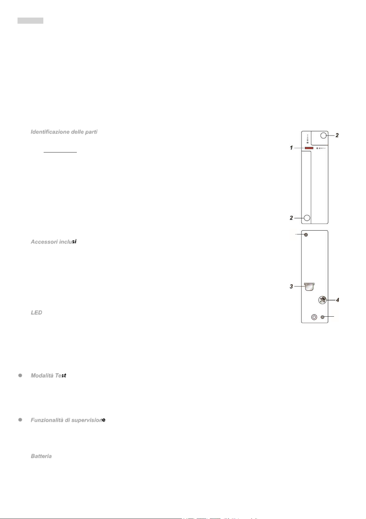
Identificazione delle parti
1. Indicatore LED rosso / Pulsante Test
Pulsante Test
Premere 1 volta per trasmettere la richiesta di apprendimento del dispositivo.
Premere 1 volta per entrare in modalità Test per 3 minuti.
2. Tappi per coprire i fori di montaggio
Rimuovere i tappini bianchi dai fori di montaggio per installare il contatto.
3. Isolante di batteria
4. Interruttore tamper (antimanomissione
L’interruttore tamper protegge il dispositivo da tentativi di apertura o rimozione dalla superficie
e di installazione.
5. Fori di montaggio
Per fissare la parte superiore e quella inferiore del contatto tramite le viti a corredo.
Accessori inclusi
a) 1 agnete
b) 2 Tappini bianchi
c) 2 Viti
d) 2 Tasselli
e) 1 Biadesivo per magnete
f) 2 viti per magnete
g) 2 spessori x magnete
LED
In modalità di funzionamento normale, l’indicatore LED è spento, eccetto che nelle seguenti situazioni:
Quando l'interruttore tamper del contatto viene aperto o chiuso
Quando il contatto è allarmato con tamper aperto o con batteria scarica
Quando il contatto entra in modalità Test
Il LED non lampeggia se il tamper e la batteria del contatto funzionano normalmente e il dispositivo non è in modalità Test.
Il LED lampeggia per indicare la trasmissione di un segnale e lampeggia rapidamente 2 volte quando riceve un segnale di riconoscimento
dall’unità di controllo.
Modalità Test
Ogni qualvolta il pulsante di Test viene premuto, il contatto trasmette un segnale all’unità di controllo per un test della portata
radio e attiva per 3 minuti la modalità di Test.
Durante il Test, il LED si accende ogni qualvolta il contatto venga attivato.
Ad ogni ulteriore pressione del pulsante di Test, la modalità Test viene prolungata di altri 3 minuti.
Funzionalità di supervisione
In funzionamento normale il contatto trasmette all’unità di controllo un segnale di supervisione ad intervalli costanti.
Se l’unità di controllo non riceve il segnale dal contatto entro un tempo prefissato, l’unità di controllo genererà un allarme di
supervisione.
Batteria
Il contatto è alimentato da una batteria al litio CR2 3 V ed è in grado di segnalare quando la batteria è scarica. Quando la batteria è
scarica, il dispositivo invia un segnale all’unità di controllo insieme alle normali trasmissioni.
Quando la batteria è scarica, il contatto non funziona e il Led lampeggia ogni 4 secondi.
5
5
DS80MM1G-001B 3
La batteria viene pre-installata in fabbrica con l’inserimento di un elemento isolante. Rimuovere l’isolante della batteria per attivare il
contatto.
Funzionamento del contatto
Il dispositivo viene appreso dall’unità di controllo premendo il pulsante di apprendimento/test.
Il dispositivo ha funzioni differenti che lavorano indipendentemente e che vengono gestite dall’unità di controllo.
Tamper
L’interruttore magnetico interno rileva l’apertura e la chiusura della porta con il magnete associato. Il tamper protegge il contatto da
tentativi di manomissione o rimozione dalla superfice di installazione.
Morsetti filari
Nella tabella sottostante vengono visualizzati i collegamenti disponibili per le morsettiere 1 e 2. Nel caso di collegamento della
morsettiera 2, la segnalazione di un allarme su questo ingresso sarà dello stesso tipo di quello segnalato dall’apertura della porta.
TABELLA 1 – COLLEGAMENTI ALLE MORSETTIERE DEL DC6002I
MORSETTIERA 1 MORSETTIERA 2
Rivelatore apertura tapparelle Rivelatore Rottura Vetri (tipo GD05PL)
Rivelatore inerziale (tipo VSD3 o MMZ01) Dispositivo con contatto NC (Normalmente Chiuso)
Preparazione
Rimuovere l’isolante dalla batteria.
Attivare la funzione di apprendimento sull’unità di controllo.
Tramite la funzione di apprendimento, abbinare l'interruttore magnetico interno/tamper e gli ingressi filari su un ingresso
dell’unità di controllo.
- Premere il pulsante di test per l’apprendimento del dispositivo.
Se il segnale è ricevuto dall’unità di controllo, essa visualizzerà le informazioni corrispondenti. Fare riferimento al manuale
dell’unità di controllo per completare la procedura di apprendimento.
Una volta appreso il contatto, impostare l’unità di controllo in modalità “Walk Test” (Test movimento), mantenere il contatto
nella posizione desiderata e premere il pulsante Test per confermare che la posizione scelta si trovi all’interno della portata
radio dell’unità di controllo.
Una volta accertato che il contatto funzioni nella posizione desiderata, è possibile procedere all'installazione.
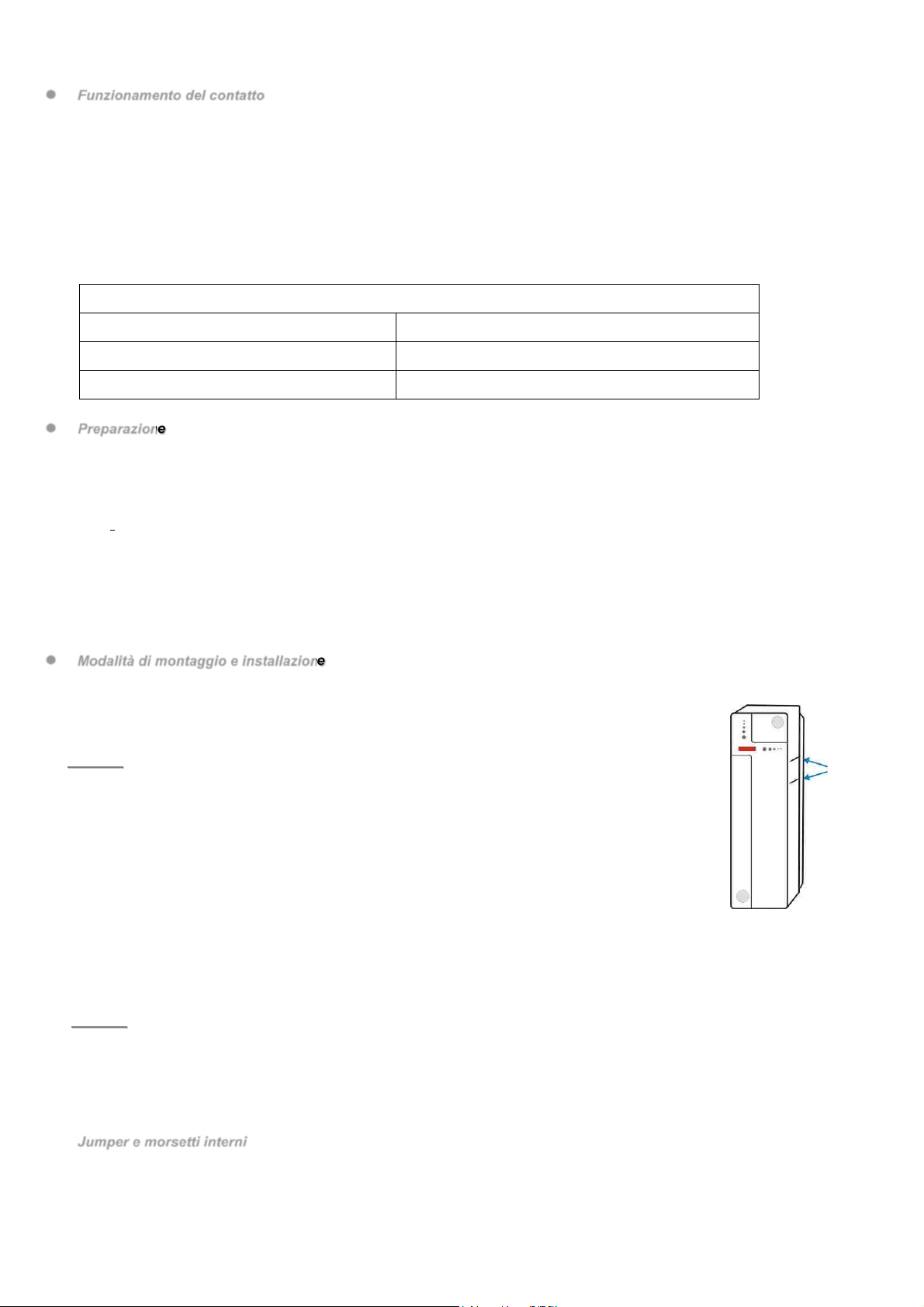
Modalità di montaggio e installazione
Il contatto deve essere posizionato sul telaio della porta, mentre il magnete deve essere posizionato
sulla porta. Se il contatto è posizionato sulla porta e la porta viene aperta troppo velocemente, la distanza
di trasmissione può essere ridotta.
Con la porta chiusa, il magnete non deve essere a più di 15 mm dal contatto.
<
<N
NO
OT
TA
A>
>
Se il contatto non può essere installato sul telaio della porta, è possibile collegare rivelatori
di apertura aggiuntivi sugli ingressi filari (per i dettagli, fare riferimento alla sezione dedicata
al collegamento dei morsetti).
Passo 1: Individuare una posizione adeguata vicino alla porta/finestra dove posizionare il contatto.
Passo 2: Il contatto presenta 2 tacche su un lato, che indicano la posizione del magnete. Il contatto può
essere installato dritto o capovolto, per garantire che le tacche siano allineate con il magnete.
Passo 3: Per montare il contatto:
(i) Utilizzando i 2 fori di montaggio del contatto come dima, marcare la posizione dei fori nella
posizione più adeguata.
(ii) Inserire i tasselli se si esegue il fissaggio su intonaco o mattoni.
(iii) Avvitare il contatto ai tasselli.
Passo 4: Posizionare il magnete sulla porta utilizzando il biadesivo o le viti in dotazione. Il magnete deve essere allineato alle
tacche laterali del contatto come illustrato in figura.
<
<N
NO
OT
TA
A>
>
Assicurarsi che la molla del tamper faccia contatto contro la superficie di appoggio passando attraverso l’apertura del
tamper.
Passo 5: Testare il contatto aprendo e chiudendo la porta o la finestra con l’unità di controllo in modalità “Walk test”.
Passo 6: Inserire i tappi bianchi nei due fori di montaggio del contatto.
Passo 7: L’installazione è stata completata.
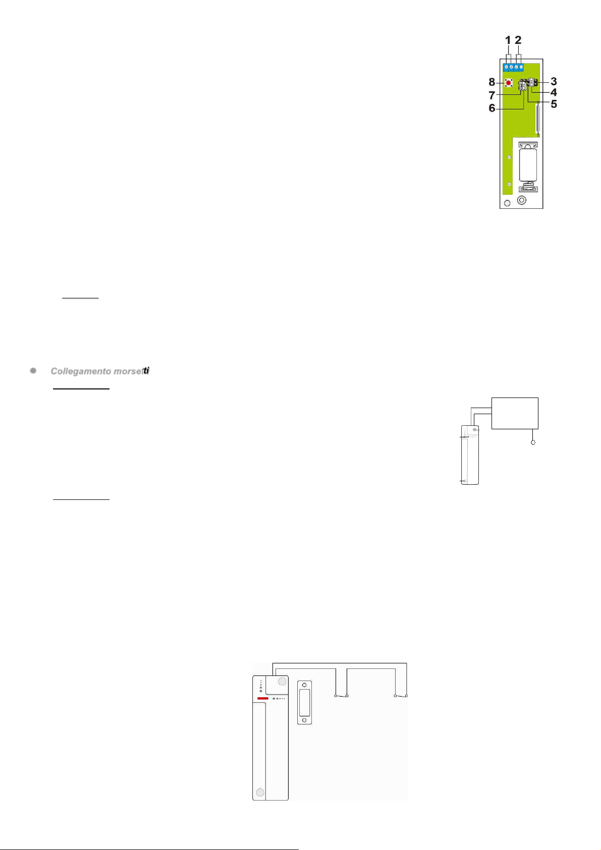
Jumper e morsetti interni
1. e 2. orsettiere. Per il collegamento si veda la Tabella 1 nella sezione Funzionamento del contatto.
La segnalazione di un allarme sull’ingresso della morsettiera 2 sarà dello stesso tipo di quello segnalato dall’apertura della
porta.
3. Jumper Riservato (JP2
Tacche
4 DS80MM1G-001B
4. Jumper abilitazione allarme porta (JP3
Questo jumper permette di abilitare/disabilitare l’allarme provocato dall’apertura porta.
Se il jumper è su ON (il jumper è inserito sui due pin), la rilevazione è disabilitata e rimangono
abilitati gli allarmi di tipo tapparella e ingresso NC.
Se il jumper è su OFF (il jumper è rimosso o “collocato” su un pin), la rilevazione è abilitata
(impostazione di default).
5. Jumper Impostazione rivelatore apertura tapparelle - 5 impulsi/disabilitato (JP4
Questo jumper permette di selezionare quanti impulsi sono necessari per attivare l’allarme di apertura
tapparelle.
Con il jumper su ON, l’allarme viene generato quando vengono contati 5impulsi in 10
secondi.
Se il jumper è su OFF, l’allarme non viene attivato dopo 5 impulsi in 10 secondi
(impostazione predefinita).
6. Jumper Impostazione rivelatore apertura tapparelle - 6 impulsi/disabilitato (JP5
Questo jumper permette di selezionare quanti impulsi sono necessari per attivare l’allarme di apertura
tapparelle.
Con il jumper su ON, l’allarme viene generato quando vengono contati 6impulsi in 10 secondi.
Se il jumper è su OFF, l’allarme non viene attivato dopo 6 impulsi in 10 secondi (impostazione predefinita).
7. Jumper Impostazione rivelatore apertura tapparelle - 8 impulsi/disabilitato (JP6
Questo jumper permette di selezionare quanti impulsi sono necessari per attivare l’allarme di apertura tapparelle.
Con il jumper su ON, l’allarme viene generato quando vengono contati 8impulsi in 10 secondi.
Se il jumper è su OFF, l’allarme non viene attivato dopo 8 impulsi in 10 secondi (impostazione predefinita).
<
<N
NO
OT
TA
A>
>
I jumper JP4, JP5 e JP6 possono essere impostati su ON solo uno alla volta.
Se più di un jumper JP4, JP5 e JP6 o nessuno di essi è impostato su ON, l’allarme si attiverà dopo 5 impulsi
contati in 10 secondi.
Il conteggio degli impulsi sarà azzerato se non saranna contati impulsi entro 10 secondi .
8. Pulsante Test
ollegamento morsetti
Morsettiera 1
L’uso dei morsetti 1 può essere utilizzato come rivelatore di apertura tapparelle e rivelatori
inerziali.
Il DC6002I è in grado di rilevare i micro movimenti (impulsi) del dispositivo collegato.
È possibile impostare l’attivazione dell’allarme con 5, 6 o 8 impulsi.
Quando non vengono rilevati gli impulsi impostati entro 10 sec, il conteggio viene azzerato.
Gli impulsi sono programmati utilizzando i jumper 4, 5, o 6. Solo uno dei tre può essere
impostato su ON. Se più di uno dei tre jumper o nessuno di essi è impostato su ON, l’allarme
si attiverà dopo 5impulsi contati in 10 secondi.
Morsettiera 2
I morsetti 2 rilevano l’apertura di un circuito Normalmente Chiuso o di un rivelatore rottura vetri. La segnalazione di un allarme
su questo ingresso sarà dello stesso tipo di quello segnalato dall’apertura della porta.
Per connettere un dispositivo esterno:
1. Aprire l’involucro allentando le viti di fissaggio.
2. La parte superiore del coperchio ha una parte rimovibile in plastica sottile. Rompere la predisposizione per i fori creando un foro
per il collegamento dei cavi ai morsetti.
3. Collegare il dispositivo ai morsetti.
I morsetti possono essere utilizzati per le seguenti situazioni.
Se il contatto non può essere installato sul telaio della porta, è possibile collegare un interruttore aggiuntivo ai morsetti e
installare il contatto a distanza.
Qualsiasi dispositivo con contatto pulito e circuito NC (Normalmente Chiuso) può essere collegato ai morsetti utilizzando il
contatto come un trasmettitore universale.
È possibile collegare insieme al contatto più dispositivi con contatto pulito, come mostrato in figura:

DS80MM1G-001B 5
Sostituzione batteria
I. Smontare il contatto, rimuovendo prima i tappi bianchi e successivamente le viti di fissaggio.
II. Aprire il contatto allentando le viti di fissaggio.
III. Rimuovere le batterie esauste e premere due volte l'interruttore Tamper per scaricare completamente il dispositivo.
IV. Inserire la nuova batteria al litio CR2 3V nell’alloggiamento, rispettando correttamente la polarità.
V. Riposizionare e stringere il coperchio.
VI. Riavvitare il contatto utilizzando le viti di fissaggio e reinserire i tappi bianchi.
Specifiche tecniche
Alimentazione: 1 batteria litio 3V tipo CR2
Autonomia batterie: 5 anni (valore tipico, può variare in base all’uso)
Frequenza radio bidirezionale: 868 MHz
Temperatura operativa: -10°C to +45°C
Dimensioni: 107 mm x 32 mm x 22 mm
Peso: 100g
Conforme alla norma EN 50131 Grado 2, ClasseⅡ
DICHIARAZIONE DI CONFORMITÀ UE SEMPLIFICATA
Il fabbricante, URMET S.p.A., dichiara che il tipo di apparecchiatura radio: CONTATTI MAGNETICI CON INGRESSI FILARI DC6002I e
DC6002I/BR è conforme alla direttiva 2014/53/UE. Il testo completo della dichiarazione di conformità UE è disponibile al seguente
indirizzo Internet: www.elkron.com
6 DS80MM1G-001B
ENGLISH
Magnetic contacts with wired inputs DC6002I and DC6002I/BR control the opening/closing of specific devices (e.g. door or a window).
The contacts are fixed onto the door or window frame, while the actuation magnets must be fixed onto the door or window itself. When
the door or window is opened, the magnet moves away from the contact making the inner magnetic switch trip and activating the sending
of an alarm signal to the control unit. The device can also send information on faults and flat battery indications. The contact consists of
a cover and a base. The cover contains all the electronic components, while the base is used for installing the device. A tamper switch
inside provides protection from unauthorised attempted to open or remove the device.
The DC6002I and DC6002I/BR contacts also have wired inputs which may be used to connect an NC (Normally Closed) contact of a
wired device or a shutter or roller opening detector (use of wire contacts for rolling blinds Elkron MF01 and MF02 is recommended).
Importantly, the Elkron glass breakage detector GD05PL may be used as wired contact while the Elkron sismic sensors VSD3 and
MMZ01 may be connected as roller opening sensor. For more details on the connections and characteristics of these products, please
refer to their manuals.
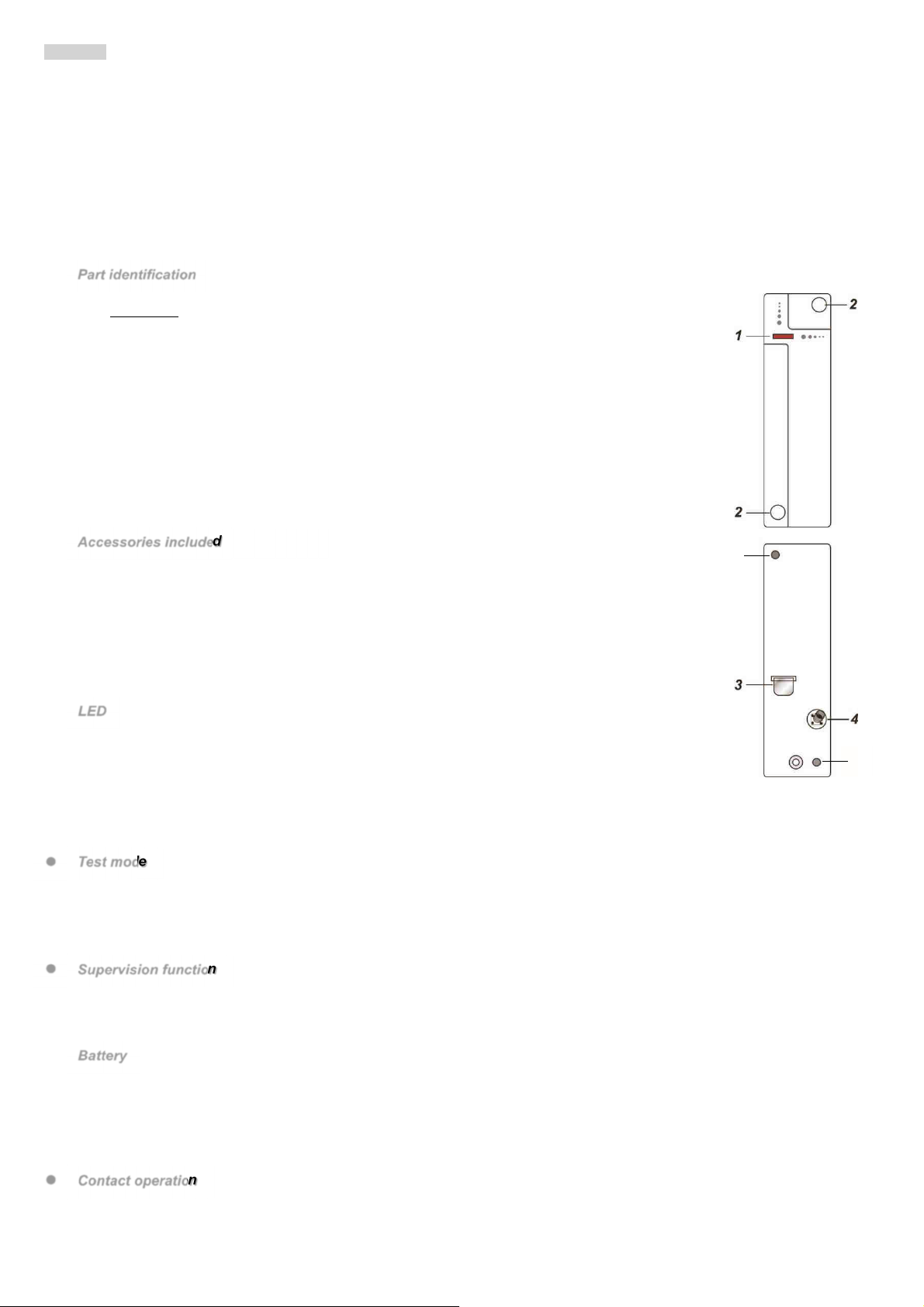
Part identification
1. Red LED indicator / Test button
Test button
Press once to transmit the device learning request.
Press once to enter Test mode for 3 minutes.
2. Plugs for covering mounting holes
Remove the white plugs from the mounting holes to install the contact.
3. Battery insulation
4. Tamper switch
The tamper switch protects the device from attempts to open it or remove it from the installation
surface.
5. Mounting holes
For fixing the upper part and the lower part of the contact using the screws provided.
Accessories included
a) magnet
b) 2 white plugs
c) 2 screws
d) 2 anchor bolts
e) 1 two-sided adhesive for magnet
f) 2 screws for magnet
g) 2 shims for magnet
LED
In normal operating mode, the LED indicator is off, except for the following situations:
When the tamper switch of the contact is opened or closed
When the contact is in alarm with the tamper switch open or the battery flat
When the contact is in Test mode
The LED does not blink if the tamper switch and the battery contact are working normally and the device is not in Test mode.
The LED blinks to indicate that a signal is being transmitted and blinks rapidly twice when it receives a recognition signal from the control
unit.
Test mode
Whenever the Test button is pressed, the contact transmits a signal to the control unit to test the radio range and activates
Test mode for three minutes.
The LED lights up whenever the contact is activated during the Test.
Test mode is extended by three more minutes if the Test button is pressed again.
Supervision function
In normal operation, the contact transmits a supervision signal to the control unit at regular intervals during normal operation.
The control unit generates a supervision alarm if the control unit does not receive the contact signal within the predetermined
time.
Battery
The contact is powered by a CR2 3 V lithium battery and can indicate when the battery is flat. When the battery is flat, the device sends
a signal to the control unit together with the normal transmissions.
When the battery is flat, the contact does not work and the LED blinks every 4 seconds.
The battery is pre-installed at the factory with the insertion of an insulating element. Remove the insulation from the battery to activate
the contact.
ontact operation
The device is learnt by the control unit by pressing the learning/test button. The device has different functions which work independently
and which are managed by the control unit.
5
5
DS80MM1G-001B 7
Tamper switch
The internal magnetic switch detects the opening and closing of the door with the associated magnet. The tamper switch protects the
contact from tampering attempts or attempts remove it from the installation surface.
Wired terminals
The table below shows the connections available for terminal blocks 1 and 2. In case of connection of the terminal block 2, the signalling
of an alarm on this input will be of the same type as that indicated by the opening of the door.
TABLE 1 – CONNECTIONS TO THE TERMINALS OF DC6002I
TERMINAL BLOCK 1 TERMINAL BLOCK 2
Roller opening detector Glass Break Detector (e.g. GD05PL)
Inertial detector (e.g. VSD3 or MMZ01) Device with NC contact (Normally Closed)
Preparation
Remove the insulation of the battery.
Activate the learn function on the control unit.
By means of the learn function, pair the internal/tamper magnetic switch and the wired inputs to an input of the control unit.
- Press the test button for the learning of the device.
If the signal is received from the control unit it will show the corresponding information. Refer to the control unit manual to
complete the learning procedure.
Once the contact learning procedure has been run, set the control unit to “Walk Test” mode, holding the contact in the required
position and press the Test button to confirm that the chosen position is within the radio range of the control unit.
Proceed with the installation after having ascertained that the contact is working in the desired position.
Mounting and installation methods
The contact must be positioned on the door frame while the magnet must be positioned on the door. If
the contact is positioned on the door and the door is opening too fast, the transmission distance may be
reduced.
The magnet must not be more than 15 mm from the contact when the door is closed.
<
<N
NO
OT
TE
E>
>
If the contact cannot be installed on the door frame, additional opening detectors can be
used on the wired inputs (see the “How to use the terminals” section for details).
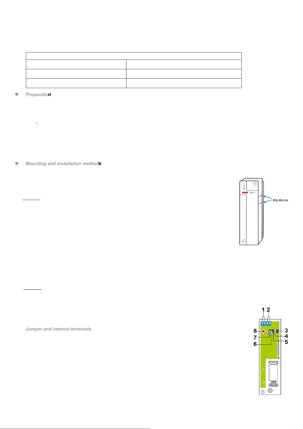
Step 1: Identify an appropriate position near the door/window where the contact is positioned.
Step 2: The contact has two rib-marks on one side which indicate the position of the magnet. The contact
may be installed straight or upside down to ensure that the rib-marks are aligned with the magnet.
Step 3: To fit the contact:
(i) Using the two mounting holes of the contact as a template, mark the position of the
holes in the more suitable position.
(ii) Insert the anchor bolts if the device is fixed to plaster or bricks.
(iii) Screw the contact onto the anchor bolts.
Step 4: Position the magnet on the door using the two-sided adhesive or the screws provided. The magnet must be aligned with
the side rib-marks of the contact as shown in the figure.
<
<N
NO
OT
TE
E>
>
ake sure that the spring of the tamper switch makes contact against the resting surface passing through the opening
of the tamper switch.
Step 5: Test the contact by opening and closing door or window with the control unit in “Walk test” mode.
Step 6: Insert the white plugs in the two mounting holes of the contact.
Step 7: The installation is complete.
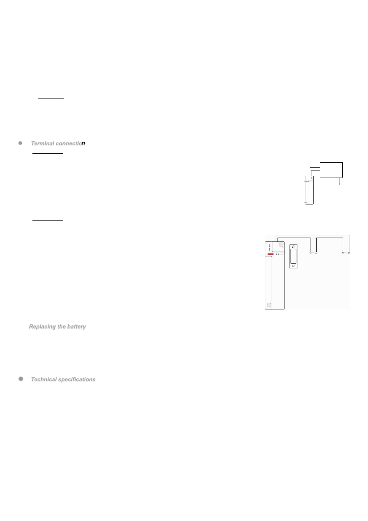
Jumper and internal terminals
1. and 2. Terminal blocks. For connection, see Table 1 in the Contact operation section
Terminals 2: the signalling of an alarm on this input will be of the same type as that indicated by the opening
of the door.
3. Reserved jumper (JP2
4. Door alarm enabled jumper (JP3
This jumper can be used to enable/disable the alarm caused by opening the door.
If the jumper is ON (the jumper is inserted on the two pins), detection is deactivated and the roller and NC input
alarms remain enabled.
If the jumper is OFF (jumper removed or "arranged" on a pin), detection is enabled (default setting).
5. Roller open detector setting jumper - 5 pulses/off (JP4
This jumper can be used to select how many pulses are needed to activate the roller opening alarm.
8 DS80MM1G-001B
With the jumper set to ON, the alarm is generated when 5pulses are counted in 10 seconds.
If the jumper is set to OFF, the alarm is not activated after 5 pulses in 10 seconds (default setting).
6. Roller open detector setting jumper - 6 pulses/off (JP5
This jumper can be used to select how many pulses are needed to activate the roller opening alarm.
With the jumper set to ON, the alarm is generated when 6pulses are counted in 10 seconds.
If the jumper is set to OFF, the alarm is not activated after 6 pulses in 10 seconds (default setting).
7. Roller open detector setting jumper - 8 pulses/off (JP6
This jumper can be used to select how many pulses are needed to activate the roller opening alarm.
With the jumper set to ON, the alarm is generated when 8pulses are counted in 10 seconds.
If the jumper is set to OFF, the alarm is not activated after 8 pulses in 10 seconds (default setting).
<
<N
NO
OT
TE
ES
S>
>
The jumpers JP4, JP5 and JP6 may be set to ON only once.
If more than one jumper JP4, JP5 and JP6 or none are set to ON, the alarm will be activated after 5 pulses
counted in 10 seconds.
The pulse count will be reset if no pulses are counted within 10 seconds.
8. Test button
Terminal connection
Terminals 1
Terminal 1 may be used as roller opening detector and inertial detector.
The device can detect the movement of the roller by checking the micro movements (pulses) of the
detection cord connected to the roller.
Alarm activation can be set with 5, 6 or 8 pulses.
The count is reset if no pulses are detected within 10 seconds.
The pulses are programmed using jumpers 4, 5 or 6. Only one of the three may be set to ON. If
more than one of the three jumpers or none are set to ON, the alarm will be activated after 5
pulses counted in 10 seconds.
Terminals 2
Terminals 2 detect the opening of a Normally Closed circuit or a glass break detector. The signalling of an alarm on this input will
be of the same type as that indicated by the opening of the door.
To connect an external device:
1. Open the casing by loosening the fixing screws.
2. The upper part of the cover has a thin removable plastic part. Break the hole setup by
creating a hole for connecting the wires to the terminals.
3. Connect the device to the terminals.
The terminals may be used for the following situations.
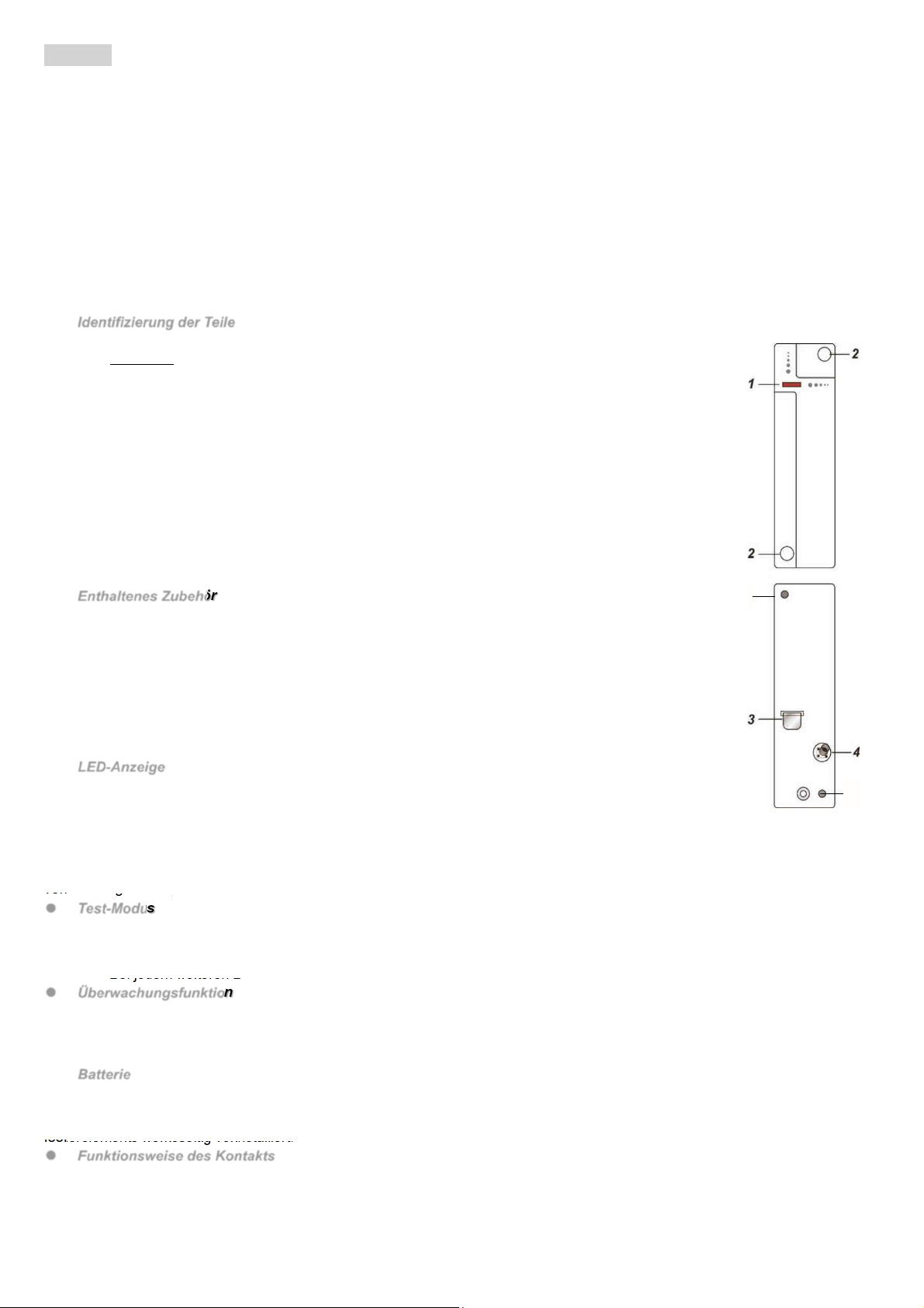
If the contact cannot be installed on the door frame, an additional switch can be connected
to the terminal and the remote contact can be installed.
Any device with no-voltage contact and NC (normally closed) circuit can be connected to
the terminals using a contact as a universal transmitter.
Multiple devices with no-voltage contact can be connected together to the contact, as
shown in the figure:
Replacing the battery
I. Remove the contact, removing the white plugs and then the fixing screws.
II. Open the open by loosening the fixing screws.
III. Remove the flat batteries and press the Tamper switch twice to discharge the device completely.
IV. Insert the new CR2 3V lithium battery in the housing, respecting the correct polarity.
V. Reposition and tighten the cover.
VI. Screw the contact back using the fixing screws and insert the white plugs again.
Technical specifications
Power supply: 1 3V CR2 lithium battery
Battery life: 5 years (typical value, may vary according to use)
Two-way radio frequency: 868 MHz
Working temperature range -10°C to +45°C
Dimensions: 107 mm x 32 mm x 22 mm
Weight: 100g
Certification EN 50131 Grade 2, Class Ⅱ
SIMPLIFIED EU DECLARATION OF CONFORMITY
Hereby, URMET S.p.A. declares that the radio equipment type: MAGNETIC CONTACTS WITH WIRED INPUTS DC6002I and
DC6002I/BR is in compliance with Directive 2014/53/EU. The full text of the EU declaration of conformity is available at the following
internet address: www.elkron.com
DS80MM1G-001B 9
DEUTSCH
Die Magnetkontakte mit den verkabelten Eingängen DC6002I und DC6002I/BR steuern das Öffnen/Schließen bestimmter Vorrichtungen
(z. B. einer Tür oder eines Fensters). Die Kontakte werden am Rahmen der Tür oder des Fensters befestigt, während die
Betätigungsmagneten auf der Tür oder dem Fenster angebracht werden. Beim Öffnen der Tür oder des Fensters entfernt sich der Magnet
von dem Kontakt, so dass der innere Magnetschalter ausgelöst und die Übertragung eines Alarmsignals an das Steuergerät aktiviert
wird. Es besteht auch die Möglichkeit, mit dem Gerät Informationen in Bezug auf Störungen und den Hinweis auf die entladene Batterie
zu versenden. Der Kontakt setzt sich aus einer Abdeckung und einer Basis zusammen. Die Abdeckung enthält alle elektronischen
Bauteile, während die Basis zur Installation des Geräts verwendet wird. Ein interner Sabotageschutz-Tamper liefert einen Schutz gegen
unbefugte Versuche des Öffnens oder Entfernens der Vorrichtung. Die Kontakte DC6002I und DC6002I/BR verfügen außerdem über
verkabelte Eingänge, die zum Anschließen eines NC-Kontakts (Ruhekontakt) eines verkabelten Geräts oder eines Öffnungsdetektors
eines Rollladens oder einer Jalousie verwendet werden können (der Einsatz der verkabelten Kontakte wird für den Rollladen von Elkron
MF01 und MF02 empfohlen).
Es wird darauf hingewiesen, dass der Glasbruchdetektor von Elkron GD05PL wie verkabelter Kontakt angeschlossen verwendet werden
kann, während der seismische Sensor von Elkron VSD3 - MMZ01 wie ein Sensor des Öffnens des Rollladens angeschlossen werden
kann. Weitere Informationen zu den Anschlüssen und Eigenschaften dieser Produkte finden Sie in deren Handbüchern.
Identifizierung der Teile
1. Rote LED-Anzeige / Test-Taste
Test-Taste
Einmal betätigen, um die Anfrage des Einlernens der Vorrichtung zu übertragen.
Einmal betätigen, um 3 inuten lang in den Test- odus zu gelangen.
2. Abdeckungen zum Verbergen der Montageöffnungen
Die weißen Abdeckungen zum Installieren des Kontakts von den ontageöffnungen entfernen.
3. Batterie-Isolator
4. Tamper-Schalter (Sabotageschutz
Der Tamper-Schalter schützt die Vorrichtung vor Versuchen des Öffnens oder Entfernens von
der Oberfläche und aus der Installation.
5. Montagebohrungen
Zum Anbringen des oberen und des unteren Teils des Kontakts mit den im
Lieferumfang enthaltenen Schrauben.
Enthaltenes Zubehör
a) 1 agnet
b) 2 weiße Abdeckungen
c) 2 Schrauben
d) 2 Dübel
e) 1 doppelseitiges Klebeband für agneten
f) 2 Schrauben für agneten
g) 2 Abstandsstücke für agneten
LED-Anzeige
In der normalen Betriebsart ist die LED-Anzeige ausgeschaltet, außer in den folgenden Situationen:
Wenn der Tamper-Schalter des Kontakts geöffnet oder geschlossen wird
Wenn der Kontakt bei geöffnetem Tamper oder entladener Batterie ausgelöst wird
Wenn der Kontakt sich in den Test-Modus begibt
Die LED blinkt nicht, wenn der Tamper und die Batterie des Kontakts normal funktionieren und die Vorrichtung sich nicht im Test-Modus
befindet. Die LED blinkt, um die Übertragung eines Signals anzuzeigen und blinkt zwei Mal schnell, wenn sie ein Signal des Erkennens
vom Steuergerät empfängt.
Test-Modus
Bei jedem Betätigen der Test-Taste überträgt der Kontakt ein Signal für einen Test der Funkreichweite an das Steuergerät
und aktiviert 3 Minuten lang den Test-Modus.
Während des Tests schaltet sich die LED bei jedem Aktivieren des Kontakts ein.
Bei jedem weiteren Betätigen der Test-Taste wird der Test-Modus für weitere 3 Minuten verlängert.
Überwachungsfunktion
Im Normalbetrieb überträgt der Kontakt in regelmäßigen Abständen ein Überwachungssignal an das Steuergerät.
Erhält das Steuergerät das Signal vom Kontakt nicht innerhalb einer festgelegten Zeit, generiert das Steuergerät einen
Überwachungsalarm.
Batterie
Der Kontakt wird von einer Lithium-Batterie CR2 3 V gespeist und ist in der Lage, die entladene Batterie anzuzeigen. Bei entladener
Batterie sendet die Vorrichtung zusammen mit den normalen Übertragungen ein Signal an das Steuergerät.
Bei entladener Batterie ist der Kontakt außer Betrieb und die LED blinkt alle 4 Sekunden. Die Batterie wird unter Einfügen eines
Isolierelements werksseitig vorinstalliert. Den Isolator der Batterie entfernen, um den Kontakt zu entfernen.
Funktionsweise des Kontakts
Die Vorrichtung wird vom Steuergerät durch Betätigen der Test-/Einlerntaste eingelesen.
Die Vorrichtung hat unterschiedliche Funktionen, die unabhängig arbeiten und von dem Steuergerät verwaltet werden.
Tamper
Der innere Magnetschalter erfasst das Öffnen und Schließen der Tür mit dem zugeordneten Magneten. Der Tamper schützt den Kontakt
vor Versuchen der Beschädigung oder des Entfernens von der Oberfläche der Installation.
5
5
10 DS80MM1G-001B
Verkabelte Klemmen
Die folgende Tabelle zeigt die verfügbaren Anschlüsse für die Klemmenblöcke 1 und 2.
Klemme 2: wird für den Anschluss an jede beliebige Vorrichtung mit NC-Kontakt (Ruhekontakt) verwendet. Die Anzeige eines Alarms
auf diesem Eingang entspricht dem Typ des durch das Öffnen der Tür angezeigten Alarms.
TABELLE 1 - VERBINDUNGEN ZU DEN TERMINALS VON DC6002I
KLEMME 1 KLEMME 2
Detektor-Fensterläden öffnen Glasbruchmelder (type GD05PL)
Inertial Detektor (type VSD3 o MMZ01) Gerät mit Öffner (normalerweise geschlossen)
Vorbereitung
Den Isolator von der Batterie entfernen.
Auf dem Steuergerät die Einlernfunktion aktivieren.
Mit Hilfe der Einlernfunktion den inneren Magnetschalter/Tamper und die verkabelten Eingänge auf einem Eingang des
Steuergeräts kombinieren.
- Zum Einlernen der Vorrichtung die Test-Taste betätigen.
Wurde das Signal vom Steuergerät empfangen, so zeigt dieses die entsprechenden Informationen an. Beziehen Sie sich auf
die Bedienungsanleitung des Steuergeräts, um den Einlernvorgang abzuschließen.
Sobald der Kontakt eingelernt wurde, das Steuergerät auf den Modus "Walk Test" einstellen (Bewegungstest), den Kontakt
in der gewünschten Position halten und die Test-Taste betätigen, um zu bestätigen, dass die gewählte Position sich innerhalb
der Funkreichweite des Steuergeräts befindet.
Sobald sichergestellt wurde, dass der Kontakt in der gewünschten Position funktioniert, kann mit der Installation begonnen
werden.
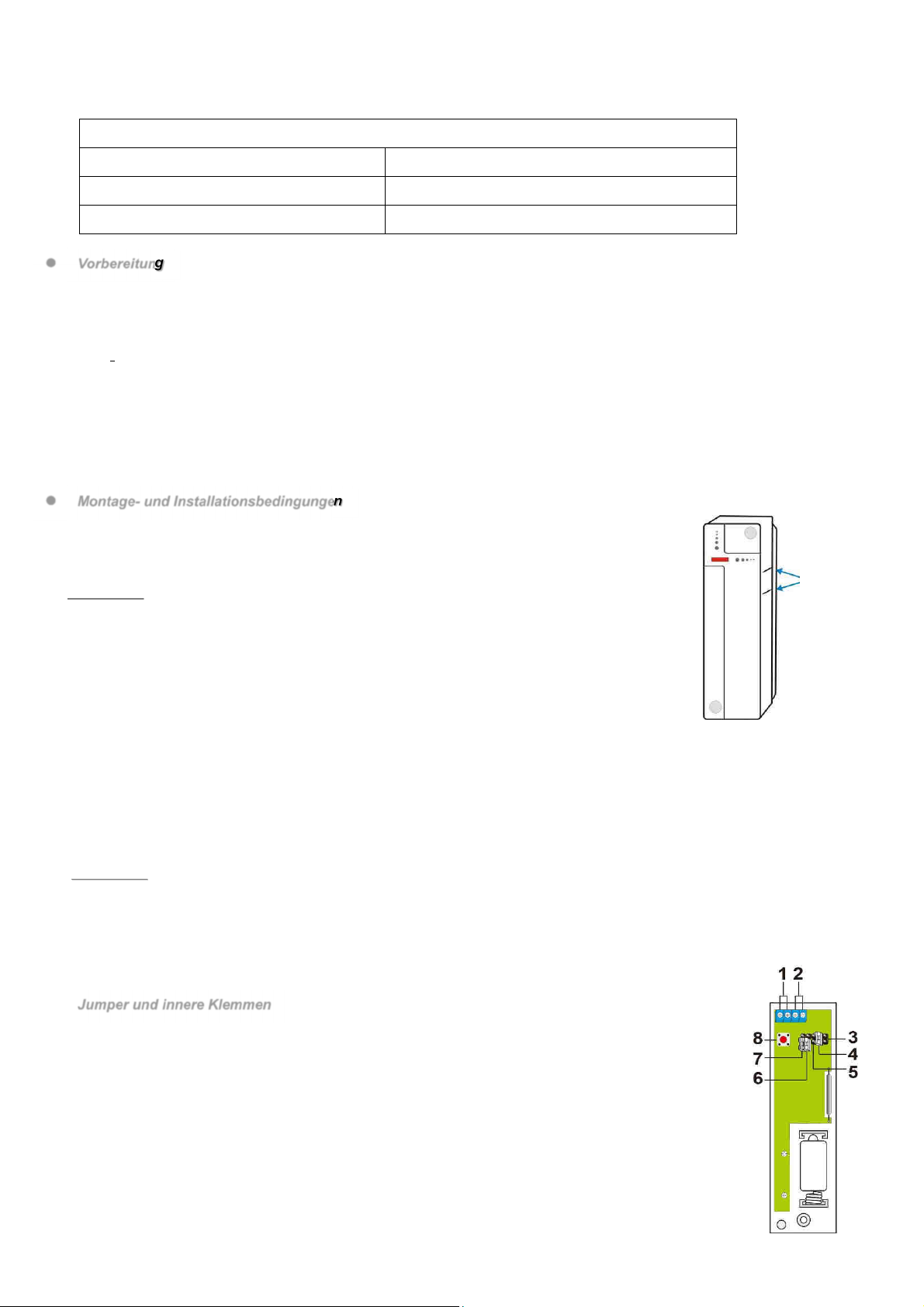
Montage- und Installationsbedingungen
Der Kontakt muss auf dem Türrahmen positioniert werden, während der Magnet auf der Tür
positioniert werden muss. Ist der Kontakt auf der Tür positioniert und die Tür wird zu schnell
geöffnet, kann sich der Übertragungsabstand verringern.
Bei geschlossener Tür darf sich der Magnet nicht weiter als 15 mm vom Kontakt entfernt befinden.
<
<H
HI
IN
NW
WE
EI
IS
S>
>
Kann der Kontakt nicht auf dem Türrahmen installiert werden, können zusätzliche elder
des Öffnens auf den verkabelten Eingängen angeschlossen werden (wegen Einzelheiten
siehe Abschnitt "Einsatz der Klemmen").
Schritt 1: achen Sie eine geeignete Position in der Nähe der Tür/des Fensters aus, in der der
Kontakt positioniert werden soll.
Schritt 2: Der Kontakt weist auf einer Seite 2 arkierungen auf, die die Position des agneten
angeben. Der Kontakt kann gerade oder umgekehrt installiert werden, um zu garantieren,
dass die arkierungen mit dem agneten ausgerichtet sind.
Schritt 3: Zur ontage des Kontakts:
(i) Verwenden Sie die beiden ontagebohrungen des Kontakts als Schablone, um die Position der Bohrungen in der am
besten geeigneten Position anzuzeichnen.
(ii) Die Dübel einsetzen, wenn die Befestigung auf Verputz oder Ziegel erfolgt.
(iii) Den Kontakt an den Dübeln verschrauben.
Schritt 4: Den agnet unter Verwendung des doppelseitigen Klebebands oder der Schrauben im Lieferumfang positionieren. Der
agnet muss mit den seitlichen arkierungen des Kontakts ausgerichtet sein, wie in der Abbildung angegeben.
<
<H
HI
IN
NW
WE
EI
IS
S>
>
Sich vergewissern, dass die Feder des Tamper-Schalters mit der Auflagefläche Kontakt hat, indem die Öffnung des
Tamper-Schalters überquert wird.
Schritt 5: Den Kontakt testen, indem die Tür oder das Fenster bei Steuergerät im odus "Walk Test" geöffnet und geschlossen
wird.
Schritt 6: Die weißen Abdeckungen in die beiden ontageöffnungen des Kontakts einsetzen.
Schritt 7: Die Installation ist abgeschlossen.
Jumper und innere Klemmen
1. - 2. Klemmen. Zum Anschluss siehe Tabelle 1 im Abschnitt Funktionsweise des Kontakts
Klemmen 2: Eine beliebige Vorrichtung mit NC-Kontakt (Ruhekontakt) anschließen. Die Anzeige
eines Alarms auf diesem Eingang entspricht dem Typ des durch das Öffnen der Tür angezeigten
Alarms.
3. Vorbehaltener Jumper (JP2
4. Jumper Aktivierung Türalarm (JP3
Dieser Jumper gestattet das Aktivieren/Deaktivieren des durch das Öffnen der Tür ausgelösten Alarms.
Befindet sich der Jumper auf ON (der Jumper ist auf den beiden Pins eingesetzt), ist die Erfassung
deaktiviert und die Alarme des Typs Rollladen und NC-Eingang bleiben aktiviert.
Befindet sich der Jumper auf OFF (der Jumper wurde entfernt oder auf einem Pin "untergebracht"), ist
die Erfassung aktiviert (Standardeinstellungen).
5. Jumper Einstellung Detektor Öffnen Rollläden - 5 Impulse/deaktiviert (JP4
Dieser Jumper gestattet das Auswählen der Anzahl der zum Aktivieren des Alarms des Öffnens der
Rollläden notwendigen Impulse.
Markierungen
DS80MM1G-001B 11
Mit dem Jumper auf ON wird der Alarm generiert, wenn 5Impulse in 10 Sekunden gezählt werden.
Bei Jumper auf OFF wird der Alarm nicht nach 5 Impulsen in 10 Sekunden aktiviert(Voreinstellung).
6. Jumper Einstellung Detektor Öffnen Rollläden - 6 Impulse/deaktiviert (JP5
Dieser Jumper gestattet das Auswählen der Anzahl der zum Aktivieren des Alarms des Öffnens der Rollläden notwendigen
Impulse.
it dem Jumper auf ON wird der Alarm generiert, wenn 6 Impulse in 10 Sekunden gezählt werden.
Bei Jumper auf OFF wird der Alarm nicht nach 6 Impulsen in 10 Sekunden aktiviert(Voreinstellung).
7. Jumper Einstellung Detektor Öffnen Rollläden - 8 Impulse/deaktiviert (JP6
Dieser Jumper gestattet das Auswählen der Anzahl der zum Aktivieren des Alarms des Öffnens der Rollläden notwendigen
Impulse.
it dem Jumper auf ON wird der Alarm generiert, wenn 8 Impulse in 10 Sekunden gezählt werden.
Bei Jumper auf OFF wird der Alarm nicht nach 8 Impulsen in 10 Sekunden aktiviert(Voreinstellung).
<
<H
HI
IN
NW
WE
EI
IS
S>
>
Von den Jumpern JP4, JP5 und JP6 kann jeweils nur einer auf ON gestellt werden.
Ist mehr als einer der Jumper JP4, JP5 und JP6 oder keiner davon auf ON gestellt, wird der Alarm nach 5 in 10
Sekunden gezählten Impulsen aktiviert.
Die Impulszählung wird auf Null gestellt, wenn nicht innerhalb von 10 Sekunden Impulse gezählt werden.
8. Test-Taste
Klemmenanschluss
Klemmen 1
Die Verwendung der Klemmen 1 kann als Detektor des Öffnens der Rollläden fungieren und
Inertial Detektor.
Die Vorrichtung ist in der Lage, die Bewegung des Rollladens zu erfassen, indem die
ikrobewegungen (Impulse) der an die Rollläden angeschlossenen Erfassungsschnur
kontrolliert werden.
Die Aktivierung des Alarms kann mit 5, 6 oder 8 Impulsen eingegeben werden.
Werden die eingegebenen Impulse nicht innerhalb von 10 s erfasst, wird die Zählung auf
Null gestellt.
Die Impulse werden über die Jumper 4, 5 oder 6 programmiert. Nur einer der drei darf auf ON gestellt sein. Ist mehr als
einer oder keiner davon auf ON gestellt, wird der Alarm nach 5in 10 Sekunden gezählten Impulsen aktiviert.
Klemmen 2
Die Klemmen 2 erfassen das Öffnen eines Ruhekontaktkreises oder ein Glasbruchmelder. Die Anzeige eines Alarms auf diesem
Eingang entspricht dem Typ des durch das Öffnen der Tür angezeigten Alarms.
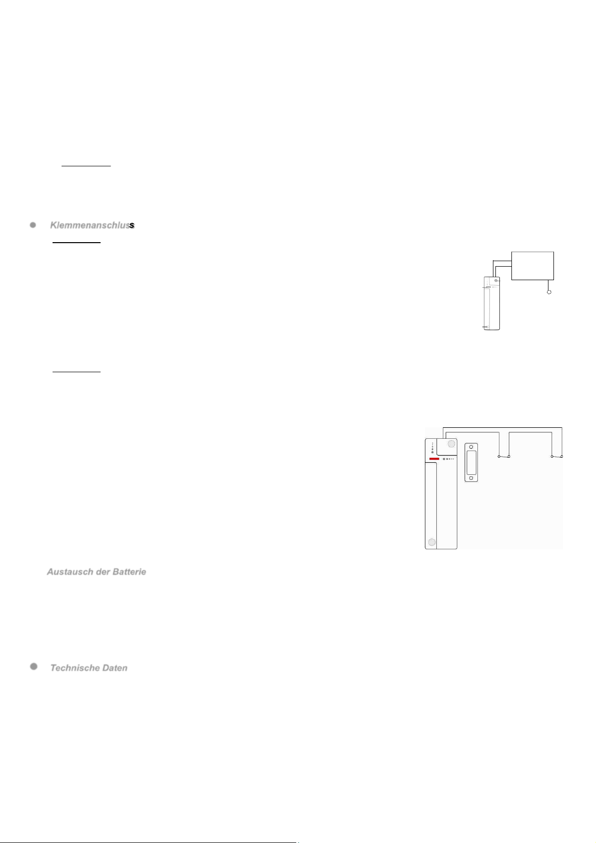
Zum Anschließen einer externen Vorrichtung:
1. Das Gehäuse durch Lösen der Befestigungsschrauben öffnen.
2. Im oberen Teil der Abdeckung befindet sich ein abnehmbarer Teil aus dünnem Kunststoff.
Den für die Bohrungen vorgesehenen Bereich durchbrechen und eine Bohrung für den
Anschluss der Kabel an die Klemmen schaffen.
3. Die Vorrichtung an die Klemmen anschließen.
Die Klemmen können für die folgenden Situationen verwendet werden.
Kann der Kontakt nicht auf dem Türrahmen installiert werden, kann ein zusätzlicher
Schalter an die Klemmen angeschlossen und der Fernkontakt installiert werden.
Sämtliche Vorrichtungen mit spannungsfreiem Kontakt und NC-Kreis (Ruhekontakt) kann
an die Klemmen unter Verwendung des Kontakts als Universalsender angeschlossen
werden.
Zusammen mit dem Kontakt können mehrere Vorrichtungen mit spannungsfreiem
Kontakt angeschlossen werden, wie in der Abbildung dargestellt:
Austausch der Batterie
I. Den Kontakt ausbauen und dazu zuerst die weißen Abdeckungen und anschließend die Befestigungsschrauben entfernen.
II. Den Kontakt durch Lösen der Befestigungsschrauben öffnen.
III. Die leeren Batterien entfernen und den Tamper-Schalter zweimal betätigen, um die Vorrichtung vollständig zu entladen.
IV. Die neue Lithium-Batterie CR2 3V in das Fach einlegen und dabei die korrekte Polarität beachten.
V. Die Abdeckung wieder einsetzen und festziehen.
VI. Den Kontakt unter Verwendung der Befestigungsschrauben wieder verschrauben und die weißen Abdeckungen wieder
einsetzen.
Technische Daten
Versorgungsspannung: 1 3V-Lithium-Batterie Typ CR2
Batterieautonomie: 5 Jahre (normaler Wert, kann je nach Verwendung schwanken)
Bidirektionale Funkfrequenz: 868 MHz
Betriebstemperatur: -10°C bis +45°C
- Abmessungen: 107 mm x 32 mm x 22 mm
Gewicht: 100 g
Zertifizierung EN 50131 Grad 2, KlasseⅡ
VEREINFACHTE EU-KONFORMITÄTSERKLÄRUNG
Hiermit erklärt URMET S.p.A., dass der Funkanlagentyp MAGNETKONTAKTE MIT DEN VERKABELTEN EINGÄNGEN DC6002I und
DC6002I/BR der Richtlinie 2014/53/EU entspricht. Der vollständige Text der EU-Konformitätserklärung ist unter der folgenden
Internetadresse verfügbar: www.elkron.com.
12 DS80MM1G-001B
FRANÇAIS
Les contacts magnétiques avec entrées filaires DC6002I et DC6002I/BR contrôlent l’ouverture/fermeture de dispositifs particuliers (par
exemple une porte ou une fenêtre). Les contacts sont fixés au châssis de la porte ou de la fenêtre, tandis que les aimants sont placés
sur la porte ou sur la fenêtre.
Quand la porte ou la fenêtre est ouverte, l’aimant s’éloigne du contact, activant l’interrupteur magnétique interne et la transmission d’un
signal d’alarme à l’unité de contrôle. Le dispositif peut aussi envoyer des informations concernant des anomalies ou le signal de pile
épuisée. Le contact est composé d’un couvercle et d’une base. Le couvercle contient tous les composants électroniques, tandis que la
base est utilisée pour l’installation du dispositif.
Un interrupteur anti-sabotage interne protège contre les tentatives non autorisées d’ouverture ou d’arrachement du dispositif. Les
contacts DC6002I et DC6002I/BR disposent aussi d’entrées filaires qui peuvent être utilisées pour raccorder un contact NF (normalement
fermé) d’un dispositif filaire ou d’un détecteur d’ouverture d’un store ou volet roulant (l’utilisation des contacts filaires pour store Elkron
MF01 et MF02 est conseillée).
A noter que le détecteur de bris de vitre Elkron GD05PL peut être utilisé raccordé comme un contact filaire, tandis que le détecteur
sismique Elkron VSD3 et MMZ01 peut être raccordé comme un détecteur d’ouverture de volet roulant. Pour plus de détails sur les
connexions et les caractéristiques de ces produits, veuillez vous reporter à leurs manuels.
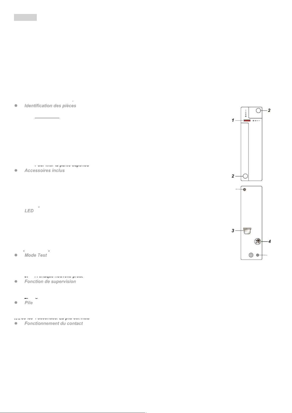
Identification des pièces
1. Indicateur LED rouge / Touche Test
Touche Test
Appuyer 1 fois pour transmettre la demande d’apprentissage du dispositif .
Appuyer 1 fois pour accéder au mode Test pendant 3 minutes.
2. Bouchons pour couvrir les trous de montage
Enlever les bouchons blancs des trous de montage pour installer le contact.
3. Isolateur de la pile
4. Interrupteur anti-sabotage (tamper)
L’interrupteur anti-sabotage protège le dispositif contre les tentatives d’ouverture ou
d’arrachement de la surface d’installation.
5. Trous de montage
Pour fixer la partie supérieure et inférieure du contact avec les vis fournies.
Accessoires inclus
a) 1 Aimant
b) 2 bouchon blancs
c) 2 Vis
d) 2 Chevilles
e) 1 ruban biadhésif pour aimant
f) 2 vis pour aimant
g) 2 cales pour aimant
LED
En mode de fonctionnement normal, l’indicateur LED est éteint, sauf dans les conditions suivantes :
Quand l’interrupteur anti-sabotage du contact est ouvert ou fermé
Quand le contact est activé avec interrupteur anti-sabotage ouvert ou pile épuisée
Quand le contact entre en mode Test
La LED ne clignote pas si l’interrupteur anti-sabotage et la pile du contact fonctionnent normalement et le
dispositif n’est pas en mode Test. La LED clignote pour montrer la transmission d’un signal et clignote vite 2
fois quand elle reçoit un signal d’identification de l’unité de contrôle.
Mode Test
1. À chaque pression de la touche de Test le contact transmet un signal à l’unité de contrôle pour
tester la portée radio et active le mode Test pendant 3 minutes.
2. Pendant le Test, la LED s’allume chaque fois que le contact est activé.
3. À chaque nouvelle pression de la touche de Test, le mode Test est prolongé de 3 minutes.
Fonction de supervision
1. Dans des conditions normales de fonctionnement le contact transmet à l’unité de contrôle un signal de supervision à intervalles
réguliers.
2. Si l’unité de contrôle ne reçoit pas de signal dans un temps déterminé, elle activera une alarme de supervision.
Pile
Le contact est alimenté par une pile au lithium CR2 3 V et peut signaler si la pile est épuisée. Quand la pile est épuisée, le dispositif
envoie un signal à l’unité de contrôle avec les autres données. Quand la pile est épuisée, le contact ne fonctionne pas et la Led clignote
toutes les 4 secondes. La pile est installée en usine avec un élément isolant. Enlever l’isolateur de la pile pour activer le contact.
Fonctionnement du contact
L’apprentissage du dispositif est effectué à partir de l’unité de contrôle en appuyant sur la touche d’apprentissage/test. Les différentes
fonctions du dispositif sont indépendantes et sont gérées par l’unité de contrôle.
Interrupteur anti-sabotage (Tamper)
L’aimant permet à l’interrupteur magnétique de détecter l’ouverture et la fermeture de la porte. L’Interrupteur anti-sabotage protège le
contact contre les tentatives d’arrachement de la surface d’installation.
Bornes filaires
Le tableau ci-dessous indique les connexions disponibles pour les borniers 1 et 2. En cas de connexion du bornier 2, la signalisation
d’une alarme sur cette entrée sera du même type que celle signalée à l’ouverture de la porte.
5
5

DS80MM1G-001B 13
TABLEAU 1 - CONNEXION DES BORNES DU DC6002I
BORNES 1 BORNES 2
Détecteur d’ouverture des volets roulants Détecteur de bris de verre (tipo GD05PL)
Détecteur inertiel (tipo VSD3 o MMZ01) Appareil avec contact NC (normalement fermé)
Procédure d’apprentissage
1. Enlever l’isolateur de la pile.
2. Activer la fonction d’apprentissage sur l’unité de contrôle.
3. Avec la fonction d’apprentissage, associer l’interrupteur magnétique interne/tamper et les entrées filaires sur une entrée de
l’unité de contrôle.
- Appuyer sur la touche de test pour l’apprentissage du dispositif.
4. Si le signal est reçu par l’unité de contrôle, celle-ci affichera les informations relatives. Consulter le manuel de l’unité de
contrôle pour compléter la procédure d’apprentissage.
5. Après que le contact a été acquis, configurer l’unité de contrôle en mode “Walk Test” (Test mouvement), maintenir le contact
dans la position désirée et appuyer sur la touche Test pour confirmer que la position choisie est comprise dans la portée radio de
l’unité de contrôle.
6. Après avoir vérifié que le contact fonctionne dans la position désirée, poursuivre l’installation.
Modalité de montage et d’installation
Le contact doit être placé sur le châssis de la porte, tandis que l’aimant doit être fixé au battant. Si le
contact est placé sur le battant de la porte et que celle-ci est ouverte trop vite, la portée de
transmission peut être réduite.
Avec la porte fermée, l’aimant ne doit pas se trouver à plus de 15 mm du contact.
<NOTE>
Si le contact ne peut pas être installé sur le châssis de la porte, des détecteurs
d’ouverture supplémentaires peuvent être raccordés sur les entrées filaires (pour les
détails, consulter la section « Utilisation des bornes »).
I
er
étape : Trouver une position appropriée près de la porte/fenêtre où placer le contact.
II
ème
étape : Sur un côté du contact il y 2 crans qui indiquent la position de l’aimant. Le contact
peut être installé droit ou renversé ; les crans doivent être alignés avec l’aimant.
III
ème
étape : Pour monter le contact :
(i) Utiliser les 2 trous de montage du contact comme gabarit pour marquer la position des
trous dans la position la plus appropriée.
(ii) Insérer les chevilles si le contact est fixé sur du plâtre ou des briques.
(iii) Visser le contact dans les chevilles.
IV
ème
étape : Fixer l’aimant à la porte avec le l’adhésif ou les vis fournies. L’aimant doit être aligné aux crans latéraux du contact,
comme montré dans la figure.
<NOTE>
Vérifier que le ressort de l’interrupteur anti-sabotage soit en contact avec la surface d’appui et qu’il passe à travers
l’ouverture de l’interrupteur anti-sabotage.
V
ème
étape : Avec l’unité de contrôle en mode “Walk test”, ouvrir et fermer la porte ou la fenêtre pour tester le contact.
VI
ème
étape : Insérer les bouchons blancs dans les deux trous de montage du contact.
VII
ème
étape : L’installation est terminée.
Cavaliers et bornes internes
1. et 2. Bornes. Pour la connexion, voir le tableau 1 dans la section relative au fonctionnement du
contact.
Bornes 2 : La signalisation d’une alarme sur cette entrée sera du même type que celle signalée par
l’ouverture de la porte.
3. Cavalier réservé (JP2)
4. Cavalier activation alarme porte (JP3)
Ce cavalier permet d’activer/exclure l’alarme déclenchée par l’ouverture de la porte.
Si le cavalier est configuré sur ON (le cavalier est inséré entre les deux bornes), la détection est exclue,
tandis que les alarmes volet roulant et entrée NF demeurent activées.
Si le cavalier est configuré sur OFF (le cavalier est enlevé ou placé sur une borne), la détection est activée
(configuration par défaut).
5. Cavalier Configuration détecteur ouverture volets roulants – 5 impulsions / exclu (JP4)
Ce cavalier permet de sélectionner le nombre d’impulsions nécessaires pour activer l’alarme d’ouverture
des volets roulants.
Si le cavalier est configuré sur ON, l’alarme est déclenchée après 5impulsions pendant 10 secondes.
Si le cavalier est configuré sur OFF, l’alarme n’est pas déclenchée après 5 impulsions pendant 10
secondes (configuration par défaut).
6. Cavalier Configuration détecteur ouverture volets roulants – 6 impulsions / exclu (JP5)
Ce cavalier permet de sélectionner le nombre d’impulsions nécessaires pour activer l’alarme d’ouverture
des volets roulants.
Si le cavalier est configuré sur ON, l’alarme est déclenchée après 6impulsions pendant 10 secondes.
Si le cavalier est configuré sur OFF, l’alarme n’est pas déclenchée après 6 impulsions pendant 10 secondes (configuration
par défaut).
7. Cavalier Configuration détecteur ouverture volets roulants – 8 impulsions / exclu (JP6)
Ce cavalier permet de sélectionner le nombre d’impulsions nécessaires pour activer l’alarme d’ouverture des volets roulants.
Si le cavalier est configuré sur ON, l’alarme est déclenchée après 8impulsions pendant 10 secondes.
Crans
14 DS80MM1G-001B
Si le cavalier est configuré sur OFF, l’alarme n’est pas déclenchée après 8 impulsions pendant 10 secondes (configuration
par défaut).
<
<N
NO
OT
TE
E>
>
Un seul des cavaliers JP4, JP5 et JP6 peuvent être configurés sur ON à la fois.
Si plus d’un cavalier JP4, JP5 et JP6 ou aucun d’eux n’est configuré sur ON, l’alarme sera activée après 5
impulsions comptées pendant 10 secondes.
Le comptage des impulsions sera mis à zéro si aucune impulsion ne sera comptée dans 10 secondes.
8. Touche Test
Raccordement des bornes
Bornes 1
Les bornes 1 peuvent être utilisées comme détecteur d’ouverture des volets roulants et détecteur inertiel.
Le dispositif peut détecter le mouvement du volet roulant en contrôlant les micro mouvements (impulsions) de la cordelette de
détection raccordé aux volets roulants.
Il est possible de configurer l’activation de l’alarme avec 5, 6 ou 8 impulsions.
Quand les impulsions configurées ne sont pas détectées dans 10 secondes, le comptage est
mis à zéro.
Les impulsions sont configurées avec les cavaliers 4, 5 ou 6. Seulement un des trois cavaliers
peut être configuré sur ON. Si plus d’un des trois cavaliers ou aucun d’eux n’est configuré sur
ON, l’alarme sera activée après 5impulsions pendant 10 secondes.
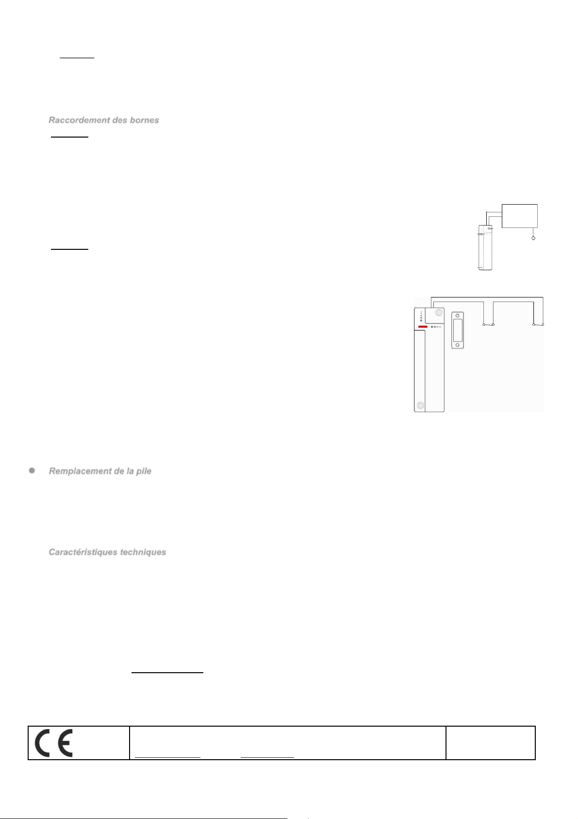
Bornes 2
Les bornes 2 détectent l’ouverture d’un circuit normalement fermé ou d’un détecteur de bris de
verre. La signalisation d’une alarme sur cette entrée sera du même type que celle signalée par
l’ouverture de la porte.
Pour raccorder un dispositif externe :
1. Desserrer les vis de fixation pour ouvrir le boîtier.
2. La partie supérieure du couvercle est dotée d’une partie amovible en plastique mince.
Défoncer les parties prédécoupées pour créer un trou pour le raccordement des câbles
aux bornes.
3. Raccorder le dispositif aux bornes.
Les bornes peuvent être utilisées pour les situations suivantes :
- Si le contact ne peut pas être installé sur le châssis de la porte, il est possible de
raccorder aux bornes un interrupteur supplémentaire et installer le contact à
distance.
-
N’importe quel dispositif avec contact libre de potentiel et circuit NF (normalement
fermé) peut être raccordé aux bornes en utilisant le contact comme un
transmetteur universel
.
Il est possible de raccorder avec le contact plusieurs dispositifs avec contact libre de potentiel, comme montré dans la figure
suivante :
Remplacement de la pile
I. Démonter le contact, enlever d’abord les bouchons blancs et ensuite les vis de fixation.
II. Desserrer les vis de fixation et ouvrir le contact.
III. Enlever les piles épuisées et appuyer deux fois sur l’interrupteur Tamper pour décharger complètement le dispositif.
IV. Insérer la nouvelle pile au lithium CR2 3V, en respectant la polarité.
V. Repositionner et serrer le couvercle.
VI. Revisser le contact avec les vis de fixation et mettre de nouveaux les bouchons blancs.
Caractéristiques techniques
Alimentation : 1 pile au lithium 3V CR2
Autonomie de pile : 5 ans (valeur typique qui peut changer selon l’utilisation)
Fréquence radio bidirectionnelle : 868 MHz
Température de fonctionnement : de -10°C à +45°C
Dimensions : 107 mm x 32 mm x 22 mm
Poids : 100g
Certification EN 50131 Grade 2, Class Ⅱ
DECLARATION UE DE CONFORMITÉ SIMPLIFIÉE
Le fabricant, URMET S.p.A., déclare que l’équipement radio : CONTACT MAGNÉTIQUE AVEC ENTRÉES FILAIRES BLANC/ MARRON
DC6002I et DC6002I/BR est conforme à la directive 2014/53/UE. Le texte complet de la déclaration UE de conformité est disponible à
l’adresse internet suivant : www.elkron.com.
ELKRON
Tel. +39 011.3986711 - Fax +39 011.3986703
www.elkron.com – mail to: [email protected]
MADE IN TAIWAN
This manual suits for next models
1
Table of contents
Languages:
Popular Household Hardware manuals by other brands

Lefroy Brooks
Lefroy Brooks X1-3091 Installation, operating, & maintenance instructions

Griffwerk
Griffwerk 417 ASSEMBLY, CARE INSTRUCTIONS, SERVICE AND MAINTENANCE

Patterson
Patterson Homecraft Rolyan AA6240 instruction sheet

Dr. Hahn
Dr. Hahn 4 AT installation instructions

Xylem
Xylem GPH Series instruction manual

TESA
TESA Powerstrips Waterproof Basket Small Product information


