Ellard CITY1-EVO User manual

ENGLISH
- 15 -
INDEX
1 - IMPORTANT REMARKS .........................................................................................................................................
2 - DISPOSAL...............................................................................................................................................................
3 - EU DECLARATION OF CONFORMITY....................................................................................................................
4 - TECHNICAL SPECIFICATIONS ................................................................................................................................
5 - DESCRIPTION OF THE CONTROL UNIT .................................................................................................................
5.1 - ELECTRIC CONNECTIONS ................................................................................................................................
5.2 - PLUG IN RECEIVER..........................................................................................................................................
6 - CONTROL PANEL ..................................................................................................................................................
6.1 - USE OF DOWN MENU AND UP KEYS FOR PROGRAMMING ............................................................................
7 - QUICK CONFIGURATION......................................................................................................................................
8 - LOADING DEFAULT PARAMETERS.......................................................................................................................
9 - SELF-LEARNING OF WORKING TIMES.................................................................................................................
10 - EMERGENCY DEAD MAN OPERATION..............................................................................................................
11 - PROGRAMMING THE CONTROL UNIT...............................................................................................................
12 - OPERATION DEFECTS .........................................................................................................................................
mATTENTION
THIS QUICK GUIDE IS ONLY USED TO START THE AUTOMATION IN ITS
BASIC CONFIGURATION. THE FULL MANUAL IS AVAILABLE ON THE V2
WEBSITE (www.v2home.com)
16
16
16
17
17
18
18
20
20
21
21
21
23
23
28

ENGLISH
- 16 -
1 - IMPORTANT REMARKS
For any installation problem please contact our Customer Service
at the number +39-0172.812411 operating Monday to Friday
from 8:30 to 12:30 and from 14:00 to 18:00.
V2 has the right to modify the product without previous
notice; it also declines any responsibility to damage or
injury to people or things caused by improper use or wrong
installation.
mPlease read this instruction manual very carefully
before installing and programming your control unit.
• This instruction manual is only for qualified technicians, who
specialize in installations and automations.
• The contents of this instruction manual do not concern the end
user.
• Every programming and/or every maintenance service should
be done only by qualified technicians.
AUTOMATION MUST BE IMPLEMENTED IN COMPLIANCE
WITH THE EUROPEAN REGULATIONS IN FORCE:
EN 60204-1 (Machinery safety. electrical equipment of
machines, part 1: general rules)
EN 12445 (Safe use of automated locking devices,
test methods)
EN 12453 (Safe use of automated locking devices,
requirements)
• The installer must provide for a device (es. magnetotermical
switch) ensuring the omnipolar sectioning of the equipment
from the power supply. The standards require a separation of
the contacts of at least 3 mm in each pole (EN 60335-1).
• After making connections on the terminal board, use one
hose clamp to fix dangerous voltage wires near the terminal
board and another hose clamp to fix safety low voltage wires
used for accessories connection; this way, in case of accidental
detachment of a conducting wire, dangerous voltage parts will
not come into contact with safety low voltage ones.
• The plastic case has an IP55 insulation; to connect flexible or
rigid pipes, use pipefittings having the same insulation level.
• Installation requires mechanical and electrical skills, therefore it
shall be carried out by qualified personnel only, who can issue
the Compliance Certificate concerning the whole installation
(EEC Machine Directive 89/392, Annex IIA).
• The automated vehicular gates shall comply with the following
rules: EN 12453, EN 12445, EN 12978 as well as any local rule
in force.
• Also the automation upstream electric system shall comply with
the laws and rules in force and be carried out workmanlike.
• The door thrust force adjustment shall be measured by means
of a proper tool and adjusted according to the max. limits,
which EN 12453 allows.
• We recommend to make use of an emergency button, to be
installed by the automation (connected to the control unit
STOP input) so that the gate may be immediately stopped in
case of danger.
• Always remember to connect the earth according to current
standards (EN 60335-1, EN 60204-1).
2 - DISPOSAL
As for the installation operations, even at the end of this product’s
life span, the dismantling operations must be carried out by
qualified experts.
This product is made up of various types of materials: some can
be recycled while others need to be disposed of.
Find out about the recycling or disposal systems envisaged by your
local regulations for this product category.
Important! – Parts of the product could contain pollutants or
hazardous substances which, if released into the environment,
could cause harmful effects to the environment itself as well as to
human health.
As indicated by the symbol opposite, throwing away this product
as domestic waste is strictly forbidden. So dispose of it as
differentiated waste, in accordance with your local regulations,
or return the product to the retailer when you purchase a new
equivalent product.
Important! – the local applicable regulations may envisage heavy
sanctions in the event of illegal disposal of this product.
3 - EU DECLARATION OF CONFORMITY
V2 S.p.A. hereby declare that CITY1-EVO products conform to the
essential requirements established in the following directives:
• 2014/30/UE (EMC Directive)
• 2014/35/UE (Low Voltage Directive)
• ROHS2 2011/65/CE
Racconigi, 01/06/2015
V2 S.p.A. legal representative.
Giuseppe Pezzetto

ENGLISH
- 17 -
4 - TECHNICAL SPECIFICATIONS 5 - DESCRIPTION OF THE CONTROL
UNIT
The digital control unit CITY1-EVO is an innovative V2 product
that guarantees a safe and reliable automation of leaf swing or
sliding gates.
CITY1-EVO is provided with a display that, not only makes
programming simple, but also allows a continuous monitoring of
the input statuses; in addition, thanks to a menu structure, the
working schedule and the operation logic can be set easily.
In compliance with the European standards concerning electrical
safety and electromagnetic compatibility (EN 60335-1,
EN 50081-1 and EN 50082-1) it has been equipped with the low
voltage circuit total electric insulation (motors included) from the
network voltage.
Other characteristics:
• Automatic control for the null current relay switch
• Allows to control ENCODER-equipped 230V motors
• Power adjustment with independent wave shutting on both
the two motors
• Obstacle detection by means of monitoring start condenser
voltage
• Automatic learning of the operation time
• Operation by means of mechanical ends of stroke connected to
the gearcase or connected in series to the motor
• Tests for safety devices (photocells, safety edges and triacs)
before each opening (as required by the referred regulations)
• Deactivation of safety inputs through the configuration menu:
no jumper is required for terminals concerning safety devices
that have not been installed, yet. You will only need to disable
this function from its relevant menu
• Control unit programming can be locked through the optional
CL1+ key
• ADI 2.0 connector for the advanced management of the ADI
devices.
• USB connector to connect the control unit to a PC and manage
through software the programming of the unit, the firmware
updates and the operation diagnostics.
• Connector for the LOW ENERGY module that allows saving
electrical energy: when the gate is standing the LOW ENERGY
module deactivates the display, the photocells and all the
devices power supplied by a terminal box.
To activate the operation of the module, it is necessary to
activate the ENERGY SAVING function (parameter EnSA = Si).
CITY1-EVO
Power supply 230V / 50Hz
Max motors load 2 x 700W
Duty clcle 40%
Consumption in stand-by
(with LOW ENERGY module installed)
0,45 W
Max accessories load 24V 10W
Protection fuse 5A
Weight 1600 g
Dimensions 295 x 230 x 100 mm
Working temperature -20 ÷ +60°C
Protection IP55
CITY1-EVO-120V
Power supply 120V / 60Hz
Max motors load 2 x 500W
Duty clcle 30%
Consumption in stand-by
(with LOW ENERGY module installed)
0,45 W
Max accessories load 24V 10W
Protection fuse 8A
Weight 1600 g
Dimensions 295 x 230 x 100 mm
Working temperature -20 ÷ +60°C
Protection IP55

ENGLISH
- 18 -
L1 Antenna
L2 Antenna shielding
L3 START - Opening control for the connection of
control devices with N.O. contact
L4 START P. - Opening controls for pedestrian access for
the connection of control devices with N.O. contact
L5 STOP - Stop command. N.C. contact
L6 Common (-)
L7 FOT1 - Photocells type 1. N.C. contact
L8 FOT2 - Photocells type 2. N.C. contact
L9 COS1 - Safety edges type 1. N.C. contact
L10 COS2 - Safety edges type 2. N.C. contact
L11 Common (-)
H1 - H2 Flashing light 230 / 120 Vac - 40W
H3 Motor M2 (OPENING)
H4 Motor M2 (COMMON)
H5 Motor M2 (CLOSING)
H6 Motor M1 (OPENING)
H7 Motor M1 (COMMON)
H8 Motor M1 (CLOSING)
LPower phase 230V / 120V
NNeutral 230V / 120V
Z1 Power output 24 Vac for photocells and other
accessories
Z2 Common for accessories power supply
Z3 Photocell/optical edge TX power supply for
functional test
Z4 - Z5 Lock 12V
Z5 - Z6 Low voltage light (12Vdc - 3W)
RM MR receiving modules
ADI 2.0 ADI 2.0 interface
USB USB connector
OVERLOAD It shows that there is an overload on accessories
power supply
MAINS It shows that the control unit is power supplied
F1 5 A (230V versions)
8 A (120V versions)
J1 - J2 - J3 Connectors for the LOW ENERGY module
REFER TO THE COMPLETE MANUAL TO CONFIGURE THESE
DEVICES
E1 FCA1 - Open limit switch
motor M1 Encoder
motor M2
E2 FCC1 - Close limit switch
motor M1
E3 FCA2 - Open limit switch
motor M2 Encoder
motor M1
E4 FCC2 - Close limit switch
motor M2
E5 Common (-)
5.1 - ELECTRIC CONNECTIONS
mWARNING: The installation of the unit, safety
devices and accessories must be carried out when the
power supply is disconnected
BEFORE PROCEEDING WITH THE ELECTRICAL
CONNECTIONS, READ CAREFULLY THE CHAPTERS
DEDICATED TO THE INDIVIDUAL DEVICES AVAILABLE IN
THE PAGES THAT FOLLOW.
5.2 - PLUG IN RECEIVER
CITY1-EVO is suitable for plugging in a Personal Pass MR receiver.
mWARNING: Pay attention to the way you connect the
removable modules.
MR1 module receiver is provided with 4 channels and each of
them is suitable for a command of CITY1-EVO control unit::
• CHANNEL 1 gSTART
• CHANNEL 2 gPEDESTRIAN START
• CHANNEL 3 gSTOP
• CHANNEL 4 gCOURTESY LIGHT
The transmitter codes can be stored in two ways:
1. By pressing the P1 button on the MR receiver (read the
instructions supplied with the receiver)
2. Using WINPPCL software: to run the program you need to
connect a PC to the control unit. The connection can be made
via USB using a standard USB cable.

ENGLISH
- 19 -
ANT
START
STOP
START P.
COM
FOT1
FOT2
COS1
COS2
COM
FCA1
FCC1
FCA2
FCC2
COM
+24VAC
COM (-)
+24VAC (TEST)
NEUTRAL
PHASE
LOCK
WARNING LIGHT
FLASHING LIGHT
ANT-
E1
OVERLOAD
RM
DOWN MENU UP
MAINS
J1 J2
J3
F1
E2 E3 E4 E5 Z1 Z2 Z3 Z4 Z5 Z6 H1 H2 H3 H4 H5 H6 H7 H8 N L
OPEN
COM
CLOSE
M2
OPEN
COM
CLOSE
M1
L1 L2 L3 L4 L5 L6 L7 L8 L9 L10 L11
mATTENTION: jumpers J1 and J2 must be removed
only to allow connection of the LOW ENERGY
optional module. Insert the module only after having
disconnected the power supply unit.
ENGLISH
- 20 -
6 - CONTROL PANEL
When power is on, the control unit checks that display correctly
operates by switching on all segments for 1.5 sec. 8.8.8.8.
Then you can see the ID of the control unit (Evo1) and the version
of the firmware (Pr 1.0).
Panel will be viewed upon completion of this test.
The control panel represents the physical status of the terminal
board contacts and of the program mode keys: if the upper
vertical segment is on, the contact is closed; if the lower vertical
segment is on, the contact is open (the above picture shows
an instance where the inputs START, START P, FOTO 1, FOTO 2,
COSTA 1, COSTA 2 and STOP have all been correctly connected).
Points being among display digits show the status of
programming push-buttons: as soon as a push-button is pressed,
its relevant point turns on.
NOTE: the “points” among the numbers, are used also to signal
the state of the remote safety devices controlled through the ADI
module.
The arrows on the display left side show the status of the ends
of stroke. As for a one door-gate, arrows turn on when its end
of stroke shows that the gate is completely closed or completely
open.
As for a two-door gate, arrows turn on when both the ends
of stroke show that both the doors are completely closed or
completely open; the arrow will blink in case only one door
reaches its end of stroke.
mWARNING: these functions have not been activated
in case of ends of stroke being connected in series to the
motor.
The arrows on the display right side show the gate status:
• The highest arrow turns on when the gate is into its opening
phase. If it blinks, it means that the opening has been caused
by a safety device (border or obstacle detector).
• The central arrow shows that the gate is on pause. If it blinks, it
means that the time countdown for the automatic closing has
been activated.
• The lowest arrow blinks when the gate is into its closing phase.
If it blinks, it means that the closing has been caused by a
safety device (border or obstacle detector).
6.1 - USE OF DOWN MENU AND UP KEYS FOR
PROGRAMMING
Control unit time and function programming is made within a
special configuration menu, to which you can access and where
you can shift through DOWN, MENU and UP keys placed under
the display.
mCAUTION: Except in the configuration menu, pressing
the UP key activates a START command and pressing the
DOWN key activates a START PEDESTRIAN command.
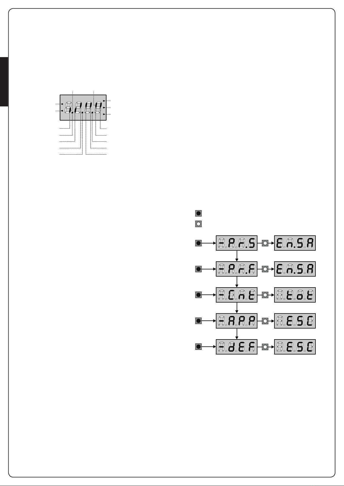
Hold down the MENU key to scroll through the 5 main menus:
-Pr.S BASE PROGRAMMING (SHORT MENU): only the useful
parameters for a base programming are displayed.
-Pr.F ADVANCED PROGRAMMING (FULL MENU) *: all
parameters of the programming menu are displayed.
-Cnt COUNTERS *
-APP SELF-LEARNING OF WORKING TIMES
-dEF LOAD DEFAULT PARAMETERS
To enter one of the 5 main menus, just release the MENU key
when the menu you want appears on the display.
To move through the 5 main menus, press the UP and DOWN keys
to scroll through the various items. Press the MENU key to display
the current value of the selected item and change it if needed.
OPENING IN PROGRESS
CLOSED CONTACTOPEN CONTACT
CLOSING
LIMIT SWITCH
OPENING
LIMIT SWITCH
PAUSE (GATE OPENED)
CLOSING IN PROGRESS
EDGE 2
EDGE 1
UP
PHOTOCELL 2
PHOTOCELL 1
START
DOWN
PEDESTRIAN START
STOP
MENU
MENU
3”
3”
MENU
6”
3”
3”
3”
MENU
9”
MENU
12”
MENU
15”
* download the full manual from the website www.v2home.com

ENGLISH
- 21 -
7 - QUICK CONFIGURATION
This paragraph concerns a quick procedure to set the control unit
and set it at work immediately.
We recommend following these instructions, in order to
check quickly the correct operation of control unit, motor and
accessories, and then changing the configuration in case of any
non-satisfactory parameter.
1. Call up the default configuration (chapter 8).
NOTE: The DEFAULT configuration includes a photocell
connected to the FOT2 input.
mWARNING: If you load the AntE DEFAULT and the
installation only requires one door, set the opening time
t.AP2 to zero.
2. Set parameters StoP, Fot1, Fot2, CoS1, CoS2 according
to the safety devices installed on the gate
3. Check that the connection of the motors is correct:
a. Feed the unit and activate the automation with a START
order: the motors must move in opening in the correct order
b. If the direction of the movement is wrong, invert the
opening/closing motor cables that move in reverse
c. If the opening order of the doors is not correct, invert the
connections of the two motors
4. Start the self-learning cycle (chapter 9)
5. Check that the automation work properly and if necessary
modify the configuration of the desired parameters
8 - LOADING OF DEFAULT
PARAMETERS
If necessary, it is possible to restore all the parameters to their
standard or default value (see table at the end)
mWARNING: This procedure causes the loss of all the
customized parameters.
1. Press and hold down the MENU key until the -dEF appears
on the display
2. Release the MENU key: the display will show ESC (press the
MENU key only if you want to leave this menu)
3. - If the unit controls a door, press the UP key: the display
shows AntE
- If the unit controls another type of automation press the
DOWN key: the display shows SCor
4. Press the MENU key: no will appear on the display.
5. Press the DOWN key: Si will appear on the display.
6. Press the MENU key: All of the parameters are returned to their
default values (chapter 11) and the display shows the control
panel
9 - SELF-LEARNING OF WORKING
TIMES
This menu allows the automatic learning of the times necessary to
open and close the gate. The encoder positions are also saved, if
enabled.
Place the doors, or door, at half run and proceed with the
following points:
NOTE: if the gate has only one door, the opening time of motor 2
must be set at 0 (t.AP2 = 0)
1. Press and hold down the MENU key until the -APP appears
on the display
2. Release the MENU key: the display will show ESC (press the
MENU key only if you want to leave this menu)
3. Press the DOWN key: t.LAv will appear on the display
4. Press the MENU key to start the self-learning cycle for the work
cycle times.
CAUTION: This procedure varies based on the number of gate
panels and travel control devices installed (refer to the tables
outlined on the following pages).

ENGLISH
- 22 -
2 MOTORS
(LIMIT SWITCHES OR SENSOR OF OBSTACLES IS ENABLED)
1. Door 1 is opened for a few
seconds
2. Door 2 is closed until the limit
switches comes into action, or
the sensor of obstacles detects
that the door is locked
3. Door 1 is closed until the limit
switches comes into action, or
the sensor of obstacles detects
that the door is locked
4. An opening manoeuvre for
each door is carried out, the
operation ends when the limit
switches comes into action, or
the sensor of obstacles detects
that the door is locked
5. A closing manoeuvre for
each door is carried out, the
operation ends when the limit
switches comes into action, or
the sensor of obstacles detects
that the door is locked
6. The detected parameters are stored and the unit is ready for
use
2 MOTORS
(NO LIMIT SWITCHES AND SENSOR OF OBSTACLES IS
DISABLED)
ATTENTION: in this case the limits of the run must be signalled
with a START order
1. Door 1 is opened for a few
seconds
2. Door 2 is closed until the unit
receives a START order
3. Door 1 is closed until the unit
receives a START order
4. An opening manoeuvre is
carried out for each door, the
operation ends when the unit
receives a START order (the first
START stops door 1, the second
START stops door 2)
5. A closing manoeuvre is
carried out for each door, the
operation ends when the unit
receives a START order (the first
START stops door 2, the second
START stops door 1)
6. The detected parameters are stored and the unit is ready for
use
1 MOTOR
(LIMIT SWITCHES OR SENSOR OF OBSTACLES IS ENABLED)
1. The door is closed until the limit
switches comes into action, or
the sensor of obstacles detects
that the door is locked
2. An opening manoeuvre is
carried out, the operation ends
when the limit switches comes
into action, or the sensor of
obstacles detects that the door
is locked
3. A closing manoeuvre is carried
out, the operation ends when
the limit switches comes
into action, or the sensor of
obstacles detects that the door
is locked
4. The detected parameters are stored and the unit is ready for
use
1 MOTOR
(NO LIMIT SWITCHES AND SENSOR OF OBSTACLES IS
DISABLED)
ATTENTION: in this case the limits of the run must be signalled
with a START order
1. The door is closed until the unit
receives a START order
2. An opening manoeuvre is
carried out, the operation ends
when the unit receives a START
order
3. A closing manoeuvre is carried
out, the operation ends when
the unit receives a START order
4. The detected parameters are stored and the unit is ready for
use

ENGLISH
- 23 -
11 - CONTROL UNIT
CONFIGURATION
Control unit time and function programming is made within a
special configuration menu, to which you can access and where
you can shift through DOWN, MENU and UP keys placed under
the display.
The configuration menu consists in a list of configurable items;
the display shows the selected item.
• By pressing DOWN, you will pass to the next item
• By pressing UP, you will return to the previous item
• By pressing MENU, you can view the current value of selected
item and possibly change it.
Based on the requirements of the installation, it is possible to
activate the SHORT or FULL programming menu.
The SHORT menu consists only of parameters useful for a
programming base, while the FULL menu consists of all the
parameters of the programming menu (the parameters present
only in the FULL menu are shown in the table).
To activate the SHORT programming menu hold the MENU key
until the display shows -Pr.S; by releasing the key, the unit
displays the first parameter of the En.SA menu.
To activate the FULL programming menu *hold the MENU key
until the display shows -Pr.F; by releasing the key, the unit
displays the first parameter of the En.SA menu.
The last menu item (FinE) allows storing the carried out changes
and going back to the control unit normal operation.
You must exit from programming mode through this menu item if
you do not want to lose your configuration.
mWARNING: in case no operation is carried out for
more than one minute, the control unit exits from the
programming mode without saving any of your setups and
changes, which will get lost.
NOTE: By holding pressed the UP key the programming menu
parameters scroll fast backwards until item En.SA is displayed.
By pressing key DOWN the programming menu parameters scroll
fast forward until item FinE is displayed.
MENU
3”
3”
10 - EMERGENCY DEAD MAN
OPERATION
This operational mode can be used to move the gate in DEAD
MAN mode in particular cases, such as installation/maintenance or
in the case of malfunctioning of photocell, edge, limit switches or
encoder.
To activate the function the START command must be pressed
3 times (presses must last at least 1 second; the pause between
commands must last at least 1 second).
1” 1” 1” T
>1” >1” >1”
The fourth START command activates the gate in MAN PRESENT
mode. To move the gate keep the START command pressed for
the duration of the operation (time T).
The function will automatically turn off after 10 seconds of
inactivity of the gate.
NOTE: if the Strt parameter is set as StAn, the Start
command (from the terminal block or remote control) moves the
gate in the open and closed directions alternatively (unlike the
normal DEAD MAN mode).
* download the full manual from the website www.v2home.com

ENGLISH
- 24 -
PARAMETER VALUE DESCRIPTION AntE SCor MEMO
En.SA ENERGY SAVING function
When the function is active and the LOW ENERGY module is installed,
the control unit deactivates the display, the photocells, and all the
devices powered by a terminal box under determined conditions.
NOTE: If the LOW ENERGY module is not installed, the control unit
deactivates only the display.
The control unit activates the ENERGY SAVING mode under the
following conditions:
• 30 seconds after completion of an operational cycle
• 30 seconds after an opening (if automatic closure is not enabled)
• 30 seconds after exiting the programming menu
The control unit exits from the ENERGY SAVING mode in these cases:
• If an operational cycle is activated
• If one of the keys on the control unit are pressed
no no
no Function deactivated
Si Function activated
t.AP1 Leaf 1 opening time 20.0” 22.5”
0.0”-5’00 Adjustable time from 0 seconds to 5 minutes
t.AP2 Leaf 2 opening time 20.0” 0.0”
0.0”-5’00 Adjustable time from 0 seconds to 5 minutes.
WARNING: if motor M2 is not connected, this time must be set to
zero
t.Ch1 Leaf 1 closing time 21.0” 23.5”
0.0”-5’00 Adjustable time from 0 seconds to 5 minutes.
NOTE: To avoid that the door does not close completely, we
recommend to setup a longer time than t.AP1 opening time.
t.Ch2 Leaf 2 closing time 21.0” 0.0”
0.0”-5’00 Adjustable time from 0 seconds to 2 minutes
NOTE: To avoid that the door does not close completely, we
recommend to setup a longer time than t.AP2 opening time
t.APP Partial opening time (pedestrian access) 6.0” 6.0”
0.0” - 2’00 When the control unit receives a Start Pedestrian command, it
will open leaf 1 only, for a shorter time.
Max allowed time to be setup is t.AP1
t.ChP Partial closing time (pedestrian access) 7.0” 7.0”
0.0” - 2’00 When the control unit receives a Start Pedestrian command, it will use
this time to close the gate. Max allowed time to be setup is t.Ch1.
NOTE: To avoid that the door does not close completely, we
recommend to setup a longer time than t.APP opening time
r.AP Opening door delay 1.0” 0.0”
0.0” - 1’00 During the opening phase, leaf 1 must start moving before leaf 2, to
avoid that both doors may collide.
Leaf 2 opening will be delayed for the setup time.
NOTE: If you set the opening door delay to zero, the control board
does not execute the control of the correct leaves closing order
r.Ch Closing door delay 3.0” 0.0”
0.0” - 1’00 During the closing phase, leaf 1 must start moving after leaf 2, to
avoid that both doors may collide.
Leaf 1 closing will be delayed for the setup time

ENGLISH
- 25 -
PARAMETER VALUE DESCRIPTION AntE SCor MEMO
Pot1 Motor M1 power 60 60
30 - 100 The displayed value is the percentage of max. motor power.
mWARNING: In case an hydraulic motor is used, set value
100
Pot2 Motor M2 power 60 60
30 - 100 The displayed value is the percentage of max. motor power.
mWARNING: In case an hydraulic motor is used, set value
100
rA.AP Slow down in opening 25 15
no Function deactivated
1 - 50 This menu allows regulating the percentage of the ride/drive that is
carried out at reduced speed during the last opening stretch
rA.Ch Slow down in closing 25 15
no Function deactivated
1 - 50 This menu allows regulating the percentage of the ride/drive that is
carried out at reduced speed during the last closing stretch
St.AP Start command during the opening phase
This menu allows fixing the control unit conduct in case it receives a
Start command during the opening phase
PAUS PAUS
PAUS The gate stops and goes to pause
ChiU The gate immediately starts closing
no The gate go on with the opening phase (command is ignored)
St.Ch Start command during the closing phase
This menu allows fixing the control unit conduct in case it receives a
Start command during the closing phase
StoP StoP
StoP The gate stops and its cycle is considered as finished
APEr The gate opens again
St.PA Start command during the pause
This menu allows fixing the control unit conduct in case it receives a
Start command when the gate is open during its pause phase
ChiU ChiU
ChiU The gate starts closing
no Command is ignored
PAUS The pause time is reset (Ch.AU)
SPAP Pedestrian Start during the partial opening phase
This menu allows fixing the control unit conduct in case it receives a
Pedestrian Start command during the partial opening phase.
mWARNING: a Start command in any phase of partial
opening will cause the total opening; the Start Pedestrian
command is always ignored during a total opening.
PAUS PAUS
PAUS The gate stops and goes to pause
ChiU The gate immediately starts closing
no The gate goes on with the opening phase (command is ignored)

ENGLISH
- 26 -
PARAMETER VALUE DESCRIPTION AntE SCor MEMO
Ch.AU Automatic closing no no
no Function deactivated
0.5” - 20.0’ The gate closes after the setup time
StoP Stop Input no no
no The input STOP is not available
ProS The input STOP stops the gate: pressing the command START the gate
continues the motion
invE The command STOP stops the gate: at the next START the gate starts
moving in the opposite direction
Fot1 Photocell 1 input
This menu allows enabling the input for type 1 photocells, that is to
say, photocells active both during the opening and closing phase
no no
no Input disabled
APCh Input enabled
Fot2 Photocell 2 input
This menu allows enabling the input for type 2 photocells, that is to
say, photocells non active during the opening phase
CFCh CFCh
CFCh Input enabled even at standstill gate too
Ch Input enabled for the closing phase only
mWARNING: If the photocell is damaged the gate is opened
anyway.
Before closing the test of the photocell (if enabled) will detect
the fault and prevent the gate from closing.
no Input disabled
CoS1 Safety edge 1 input
This menu allows enabling the input for type 1 safety edge, that is to
say, fixed edges
no no
no Input disabled
APCh Input enabled in opening and closure
AP Input enabled during the opening and disabled during the closure
CoS2 Safety edge 2 input
This menu allows enabling the input for type 2 safety edge, that is to
say mobile edges
no no
no Input disabled
APCh Input enabled in opening and closure
Ch Input enabled during the closing and disabled during the opening
This manual suits for next models
1
Table of contents
Popular Control Unit manuals by other brands


Spirax Sarco
Spirax Sarco TD3-3 Installation and maintenance instructions

Minarik
Minarik SL-15U user manual

Whelen Engineering Company
Whelen Engineering Company 295HFSA6 installation guide

CALEFFI
CALEFFI PLUMBVENT NA502640A instructions

vistaCNC
vistaCNC iMachIII P4-S manual

laerdal
laerdal Q-CPR Directions for use


