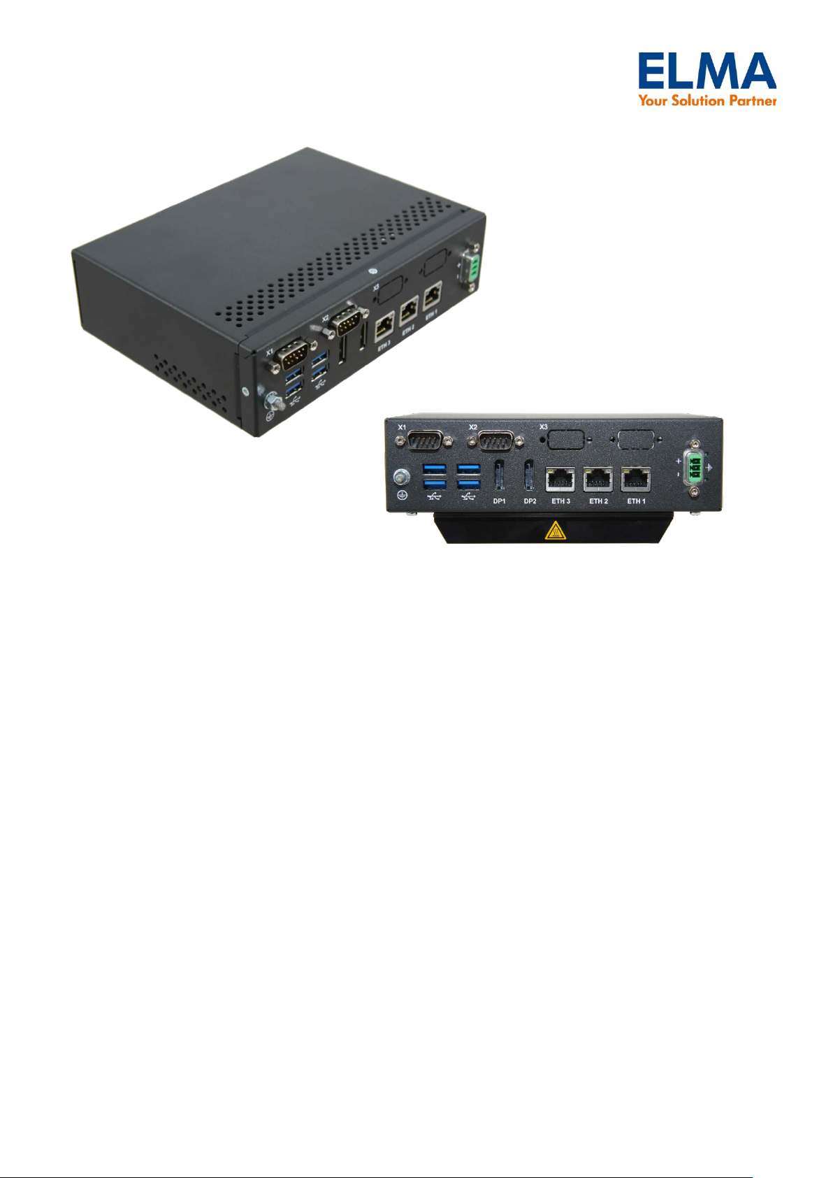
Elma ProSys-5102 User manual

ProSys-5102
Box PC with Intel® Haswell i5-4300U
Table of contents
Introduction.....................................................................................................................................2
Symbols used in this Manual........................................................................................................................ 2
Important Instructions................................................................................................................................... 2
Note on the Warranty..................................................................................................................................... 2
Technical Short Information ..........................................................................................................2
Order Information...........................................................................................................................2
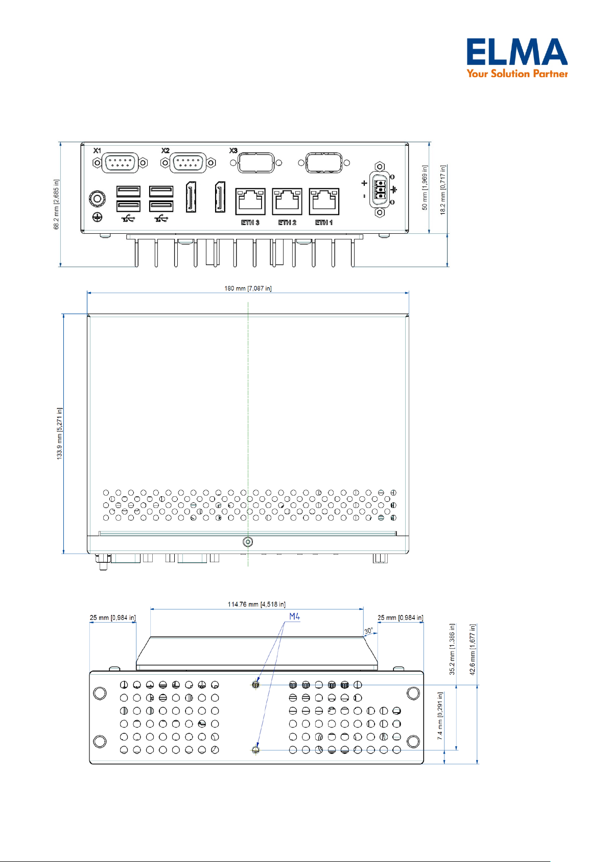
Dimensions.....................................................................................................................................3
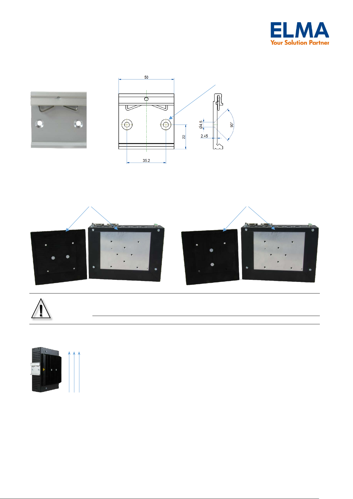
Mounting options............................................................................................................................5
Open the housing...........................................................................................................................7
CPU inside ....................................................................................................................................................... 8
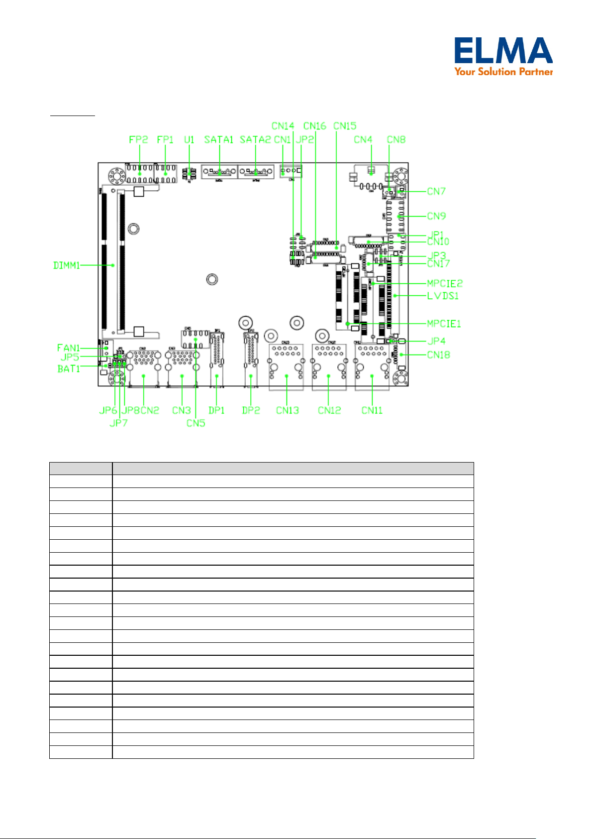
Internal Connector List:.................................................................................................................................... 9
Panel Connector List:..................................................................................................................................... 10
Jumper List:.................................................................................................................................................... 10
Jumper Settings ............................................................................................................................................. 11
BIOS Power Setting ..................................................................................................................................... 12
Panel Connector Pin Assignments ................................................................................................................ 14
Internal Connector Pin Assignment ............................................................................................................... 17
24V-to-12VDC – Converter............................................................................................................................ 23

ProSys-5102
Box PC with Intel® Haswell i5-4300U
Introduction
Symbols used in this Manual
This symbol point out to especially information.
Important Instructions
This chapter contains instructions which must be observed when using your Flatman Monitor.
The manufacturer’s instructions provide useful information on your device.
Note on the Warranty
Due to their limited service life, parts which by their nature are subject to a particularly high degree of wear
(wearing parts) are excluded from the warranty beyond that provided by law. This applies to the CMOS
battery, for example.
Technical Short Information
Housing
Interfaces
RAL 7021 powder coated
4x USB3.0
(WxDxH) 180 x 134 x 68mm (Heatsink included)
3x GbE LAN
Weight: 1300g
2x Display Port
Integrated SBC
2x COM (RS232, RS422, RS485, BIOS configurable)
CPU Intel® Haswell ULT i5-4300U
(option: w/ i7-4650)
Power
4GB RAM
(option up to 8GB)
16-30VDC Input via Phoenix Connector PSC 1,5/ 3-F
Storage: 64GB mSATA SSD
(option: up to ?GB)
OS Support
Hardware Monitor
Windows7, Windows8, Linux
Voltages, Temperature
Environment
Fanless passive cooling
EMC
Operating temp.: 0 °-50°C ambient
EN55022 class B
Humidity: 10%-90% @ 39°C, non condensing
Power Consumption
UIN
IIN
PIN
Standby
24 V
0,020 A
0,5 W
Windows IDLE
24 V
0,308 A
7,4 W
Windows typical workload (BurnIn with max. load)
24 V
0,800 A
19,2 W
Windows with CPU at TDP (Thermal Design Power selected in Thermal-analysis-
tool)
24 V
0,990 A
23,8 W
Windows with max. workload & max. Graphics adjusted in Thermal-analysis-tool
& turbo mode (max. current consumption)
24 V
1,440 A
34,6 W
Test Setup: Windows 7 pro. 64bit; 4GB RAM ; 60GB mSATA
Order Information
Order#
Description
EN00-004001-01 RAIL-PC-5101; Intel Haswell i5-4300U, 4GB RAM, 64GB mSATA
EN00-004002-01 RAIL-PC-5101; Intel Haswell i5-4300U, 8GB RAM, 128GB mSATA
EN00-004003-01 RAIL-PC-5101; Intel Haswell i5-4300U, 8GB RAM, 256GB mSATA
EN00-004004-01 RAIL-PC-5101; Intel Haswell i5-4300U, 4GB RAM, 32GB mSATA
EN00-004005-01 RAIL-PC-5101; Intel Haswell i5-4300U, 4GB RAM, 128GB mSATA

ProSys-5102
Box PC with Intel® Haswell i5-4300U
Dimensions

ProSys-5102
Box PC with Intel® Haswell i5-4300U

ProSys-5102
Box PC with Intel® Haswell i5-4300U
Mounting options

ProSys-5102
Box PC with Intel® Haswell i5-4300U
Always make sure to mount the DIN rail retaining clamp in upper position
The heatsink is flippable according to the Rail PC mounting. Make sure that the airflow always works in
upright direction.
Important note: For operating mode has to be inserted a thermal grease between heatsink
and mounting plate
(example for heatsink mounting and airflow:)
The small milling boundary of the heatsink has to be mounted to the small rim of the Box housing
mounted with two M4x8 (max. length)
counter sunk bolds

ProSys-5102
Box PC with Intel® Haswell i5-4300U
Open the housing
To open the housing just remove five screws:

ProSys-5102
Box PC with Intel® Haswell i5-4300U
CPU inside
TPM
(optional)
Speaker Out
3 X RJ45
Connectors
Audio AMP
IS31AP2010B
1 X USB2.0
PIN Header
SPI
4-DI/4-DO
Wafer USB2.0
Watch Dog
Timer
Super I/O
Fintek
F81803U
2 X COM
Ports
Intel I210-AT
GbE Controller
DP
Intel I210-AT
GbE Controller
2 X Mini-PCIE
Sockets
2 X Speaker
Connectors
2 X Display Port
Connectors
Audio Codec
Reltek
ALC662
USB3.0
1 X DDR3 SO-DIMM
Sockets
1 X LVDS
Connector
GbE PHY
Intel I218-LM
Haswell
ULT
Processors
IN/OUT/MIC
CHRONTEL
CH7511B
4 X USB3.0
Ports
PCIE x1
Block Diagram
SPI Flash
ROM
H/W
Monitor
Audio
PIN Header
DDR3LLVDS eDP
SATA
HD
LPC
2 X SATA
Connector
DI/DO
1x mPCIE / mSATA
1x mPCIE

ProSys-5102
Box PC with Intel® Haswell i5-4300U
Top View:
Internal Connector List:
Label
Function
BAT1
Battery Power Input Wafer
BZ1
Onboard Buzzer
CN1
SATA HDD Power Output Wafer
CN5
USB2.0 Port 4, 5 Pin Header
CN7
Right Channel 3W Audio AMP Output Wafer
CN8
Left Channel 3W Audio AMP Output Wafer
CN9
Audio Pin Header
CN10
Digital Input / Output Pin Header
CN14
P80_Header LPC
CN15
RS-232 / 422 / 485 Port 1 Wafer
CN16
RS-232 / 422 / 485 Port 2 Wafer
CN17
SIM Interface Wafer for MPCIE2
CN18
Backlight Power Output Wafer for LVDS1
DIMM1
DDR3 Memory SO-DIMM Socket
FAN1
C P U F A N W a f e r
FP1
Front Panel 1 Pin Header
FP2
F r o n t Panel 2 Pin Header
LVDS1
P r i m a r y 2 4 -b i t , 2 -channel LVDS Panel Connector
mPCIE1
Mini-PCIE Express v1.2 Socket / mSATA
mPCIE2
Mini-PCIE Express v1.2 Socket
SATA1
Serial ATA Port 0 Connector
SATA2
Serial ATA Port 1 Connector
/ mSATA

ProSys-5102
Box PC with Intel® Haswell i5-4300U
Panel Connector List:
Label
Function
CN2
USB3.0 Port 0,1 Connector
CN3
USB3.0 Port 2,3 Connector
CN11
GbE LAN1 RJ-45 Connector
CN12
GbE LAN2 RJ-45 Connector
CN13
GbE LAN3 RJ-45 Connector
DP1
DP Connector
DP2
DP Connector (Dual Mode)
X1
COM1
X2
COM2
PWR
Input Power Connector (3pin Phoenix)
Jumper List:
Label
Function
JP1
Panel & Backlight Power Selection for LVDS1
JP2
AT_ATX Mode / MPCIE1 mSATA / mPCIE Selection
JP3
Backlight Power Enable Selection for LVDS1
JP4
MPCIE Activity LED Indication
JP5
USB POWER Selection
JP6
Flash Description Security Over-ride
JP7
RTC Reset Selection
JP8
SRTC Reset Selection

ProSys-5102
Box PC with Intel® Haswell i5-4300U
Jumper Settings
JP1: Panel & Backlight Power Selection for LVDS1 (Pitch 2.54mm)
(not used for Rail-PC-System !!)
Jumper
Setting
Status
1
1-3
Backlight Power = +12V
3-5
Backlight Power = +5V
2
2-4
Panel Power = +3.3V
4-6
Panel Power = +5V
JP2:AT_ATX Mode / MPCIE1 mSATA / mPCIE Selection (Pitch 2.54mm)
Jumper
Setting
Status
1
1-3
ATX Mode
3-5
A T M o d e (Default)
2
2-4
mP C I E 1 m S A TA Selected (Default)
4-6
mPCIE1 mPCIE Selected
2
1
65

ProSys-5102
Box PC with Intel® Haswell i5-4300U
Importent note:
There is no „power-on-button“ on the device available:
Therefore the jumper JP2(AT/ATX Mode) has always set to „AT-Mode“!
According to this the BIOS setting for Power Mode is „Power Off“!
(Default settings ex factory)
BIOS Power Setting
Control Group Structure Name
BIOS Defaults
Possible Setting
ACPI Sleep State
S3 (Suspend to Ram)
Suspend Disabled -S3 (Suspend to Ram)
Restore AC Power LOSS
Power OFF
Power Off -Power On -Last State
Power Saving Mode
Disabled
Disabled -Enabled
Resume Event Control
Resume from S3 By PS/2
Keyboard
Disabled Disabled -Enabled
Resume from S3 By PS/2 Mouse
Disabled
Disabled -Enabled
Resume By PCIE Device
Disabled
Disabled -Enabled
Resume By RingRTC Alarm
Disabled
Disabled -Enabled
Resume By RTC Alarm
Disabled
Disabled -Enabled
►WatchDog Timer Configuration
JP3:Backlight Power Enable Selection for LVDS1 (Pitch 2.00mm)
(not used for Rail-PC-System !!)
Jumper
Setting
Status
1
1-3
Backlight
Enable
Voltage = +3.3V
3-5
Backlight
Enable
Voltage = +5V
2
2-4
Active High
4-6
Active Low
JP4:mPCIE Activity LED Indication (Pitch 2.54mm)
(not used for Rail-PC-System !!)
Pin
Description
1
LED+
2 LED-
JP5:USB Power Selection (Pitch 2.00mm)
Jumper
Status
1-2 S h o r t
USB power will be cut off in S4 & S5
state.
2-3 S h o r t
USB power will be cut off in Deep S5
state.
21
65
1
2
2
3
1

ProSys-5102
Box PC with Intel® Haswell i5-4300U
JP6: Flash Description Security Over-ride (Pitch 2.54mm)
Jumper
Status
1-2 O p e n
Disabled
1-2 S h o r t Enabled
JP7:RTC Reset Selection (Pitch 2.54mm)
Jumper
Status
1-2 O p e n
Normal Operation
1-2 S h o r t Clear RTC CMOS
JP8:SRTC Reset Selection (Pitch 2.54mm)
Jumper
Status
1-2 Open
Normal Operation
1-2 S h o r t Clear ME Registers
1
2
1
2
1
2

ProSys-5102
Box PC with Intel® Haswell i5-4300U
Panel Connector Pin Assignments
PWR: Input Power Connector
Pin
Signal
Mating connector
1 GND
Phoenix Contact
PSC 1,5/ 3-F
Order# 1841909
2 Shield
3 VCC
X1: COM1 RS-232/422/485 (via internal cable connection to CN15)
X2: COM2 RS-232/422/485 (via internal cable connection to CN16)
Pin
RS-232
RS-422
Half Duplex RS-
485
Full Duplex
RS-485
1
DCD
Tx-
DATA-
Tx-
2
RxD
Tx+
DATA+
Tx-
3
TxD
Rx+
-
Rx+
4
DTR
Rx-
-
Rx-
5
GND
GND
GND
GND
6
DSR
-
-
-
7
RTS
-
-
-
8
CTS
-
-
-
9
RI
-
-
-
CN2:USB3.0 Port-0,1 Type-A Connector
Pin
S i g n a l N a m e
Pin
S i g n a l N a m e
1
+USBA_VCC
10
+USBB_VCC
2
USBA_D-
11
USBB_D-
3
USBA_D-
12
USBB_D-
4
GND
13
GND
5
USBA_RX-
14
USBB_RX-
6
USBA_RX+
15
USBB_RX+
7
GND
16
GND
8
USBA_TX-
17
USBB_TX-
9
USBA_TX+
18
USBB_TX+
*:The power source of +USBVCC can be selected by JP5.
3
2
1

ProSys-5102
Box PC with Intel® Haswell i5-4300U
CN3: USB3.0 Port-2,3 Type-AConnector
Pin
S i g n a l N a m e
Pin
S i g n a l N a m e
1
+USBA_VCC
10
+USBB_VCC
2
USBA_D-
11
USBB_D-
3
USBA_D-
12
USBB_D-
4
GND
13
GND
5
USBA_RX-
14
USBB_RX-
6
USBA_RX+
15
USBB_RX+
7
GND
16
GND
8
USBA_TX-
17
USBB_TX-
9
USBA_TX+
18
USBB_TX+
*:The power source of +USBVCC can be selected by JP5.
CN11:GbE LAN1 RJ-45 Connector
Pin
S i g n a l N a m e
Pin
S i g n a l N a m e
1
TX1+
5
TX3-
2
TX1-
6
TX2-
3
TX2+
7
TX4+
4
TX3+
8
TX4-
CN12:GbE LAN2 RJ-45 Connector
Pin
S i g n a l N a m e
Pin
S i g n a l N a m e
1
TX1+
5
TX3-
2
TX1-
6
TX2-
3
TX2+
7
TX4+
4
TX3+
8
TX4-
CN13:GbE LAN2 RJ-45 Connector
Pin
S i g n a l N a m e
Pin
S i g n a l N a m e
1
TX1+
5
TX3-
2
TX1-
6
TX2-
3
TX2+
7
TX4+
4
TX3+
8
TX4-
LED Diagram of LAN Connectors:
(front view)
left LED: activity / link
ri g h t L E D : 10/100/1000
off No LAN connectivity off 1 0 Mbit
yellow link green 100 Mbit
blinking activity orange 1 GbE
left
right

ProSys-5102
Box PC with Intel® Haswell i5-4300U
DP1: DisplayPort Port-1Connector
Pin
Signal
Pin
Signal
1
TX0+
11
GND
2
GND
12
TX3-
3
TX0-
13
GND
4
TX1+
14
GND
5
GND
15
AUX+
6
TX1-
16
GND
7
TX2+
17
AUX-
8
GND
18
HPD
9
TX2-
19
GND
10
TX3+
20
PWR
DP2:Dual Mode DisplayPort Port-2 Connector *
Pin
Signal
Pin
Signal
1
TX0+
11
GND
2
GND
12
TX3-
3
TX0-
13
GND
4
TX1+
14
GND
5
GND
15
AUX+
6
TX1-
16
GND
7
TX2+
17
AUX-
8
GND
18
HPD
9
TX2-
19
GND
10
TX3+
20
PWR
* The Dual-Mode DisplayPort source automatically detects the presence of a plugged-in Dual-Mode DisplayPort
cable adaptor and provides the DVI or HDMI signal, as required, to support the connected DVI or HDMI
monitor

ProSys-5102
Box PC with Intel® Haswell i5-4300U
Internal Connector Pin Assignment
BAT1: Battery Power Input Wafer
Pin
S i g n a l N a m e
1
+VBAT
2
GND
CN1:SATA HDD Power Output Wafer
Pin
S i g n a l N a m e
1
+12V
2
GND
3
GND
4
+5V
CN4:Power Input Wafer (internal cable connection to DC-DC-Converter)
Pin
Signal
1
+Vin
2
GND
3
GND
4
+Vin
CN5:USB2.0 Port 10, 11 Pin Header
(not used for Rail-PC-System !!)
Pin
S i g n a l N a m e
Pin
S i g n a l N a m e
1
+USBVCC
2
+USBVCC
3
USB_A-
4
USB_B-
5
USB_A+
6
USB_B+
7
GND
8
GND
9
KEY
10
GND
*:The power source of +USBVCC can be selected b y J P 7
CN7:Right Channel 2W Audio AMP Output Wafer
(not used for Rail-PC-System !!)
Pin
S i g n a l N a m e
1
Speaker+
2
Speaker-
CN8:Left Channel 2W Audio AMP Output Wafer
(not used for Rail-PC-System !!)
Pin
S i g n a l N a m e
1
Speaker+
2
Speaker-
3
4
1
2
6
1
3
10
4
5
2
87

ProSys-5102
Box PC with Intel® Haswell i5-4300U
CN9:Audio Pin Header
(not used for Rail-PC-System !!)
Pin
S i g n a l N a m e
Pin
S i g n a l N a m e
1
MIC_IN_L
2
MIC_IN_R
3
MIC_IN_JD
4
GND
5
LINE_IN_L
6
LINE_IN_R
7
LINE_IN_JD
8
GND
9
LINE_OUT_L
10
LINE_OUT_R
11
LINE_OUT_JD
12
GND
CN10:Digital Input / Output Wafer
(not used for Rail-PC-System !!)
Pin
S i g n a l N a m e
1
+5V
2
Digital Input 0
3
Digital Output 0
4
Digital Input 1
5
Digital Output 1
6
Digital Input 2
7
Digital Output 2
8
Digital Input 3
9
Digital Output 3
10
GND
CN15 / CN16: RS-232/422/485 Port 1 / 2 Wafer
CN17:SIM Interface Wafer for MPCIE2
(not used for Rail-PC-System !!)
Pin
S i g n a l N a m e
1
UIM_PWR
2
UIM_DATA
3 UIM_RESET
4
UIM_VPP
5
UIM_CLK
6
GND
12
1 2
11

ProSys-5102
Box PC with Intel® Haswell i5-4300U
CN18: Backlight Power Output Wafer for LVDS1
(not used for Rail-PC-System !!)
Pin
S i g n a l N a m e
1
BL_ADJ_PWM *
2
BL_ADJ_VOL *
3
GND
4
+5V / +12V **
5
+5V / +12V **
6
GND
7
BL_EN***
*:BL_ADJ can be setting in BIOS setup.
**:Backlight Power can be selected by JP1.
***:BL_EN can be selected by JP3.
DIMM1:DDR3 Memory SO-DIMM Socket
FAN1:CPU FAN Wafer
(not used for Rail-PC-System !!)
Pin
Signal
1
GND
2
+12V*
3
FAN_RPM
*:PWM Fan control supported.
FP1: Front Panel 1 Pin Header
Pin
Signal
Pin
Signal
1
Reset Button +
2
Speaker +
3
Reset Button -
4
NC
5
H D D L E D +
6
Internal Speaker-
7
H D D L E D -
8
Speaker -
Note:Internal Buzzer is enabled when Pin6-8 is shorted.
FP2: Front Panel 2 Pin Header
Pin
Signal
Pin
Signal
1
Po w e r L E D +
2
Power Button +
3
NC
4
Power Button -
5
P o w e r L E D -
6
SMBALERT#
7
BATLOW#
8
SMBus Data
9
GND
10
SMBus Clock
1
3
2
-+
SPKR
+
78
HLED
21
-
+
RSTBTN
-

ProSys-5102
Box PC with Intel® Haswell i5-4300U
LVDS1: Primary 24-bit, 2-channel LVDS Panel Connector
(not used for Rail-PC-System !!)
Pin
S i g n a l N a m e
Pin
S i g n a l N a m e
1
LVDS_A0-
16
LVDS_B1+
2
LVDS_A0+
17
GND
3
LVDS_A1-
18
LVDS_B2-
4
LVDS_A1+
19
LVDS_B2+
5
LVDS_A2-
20
LVDSBCLK-
6
LVDS_A2+
21
LVDS_BCLK+
7
GND
22
LVDS_B3-/NC
8
LVDS_ACLK-
23
LVDS_B3+/NC
9
LVDS_ACLK+
24
GND
10
LVDS_A3-/NC
25
DDC_DATA
11
LVDS_A3+/NC
26
VDDEN
12
LVDS_B0-
27
DDC_CLK
13
LVDS_B0+
28
+3.3V / +5V *
14
GND
29
+3.3V / +5V *
15
LVDS_B1-
30
+3.3V / +5V *
*:Panel Power can be selected by JP1.
Table of contents
Popular Desktop manuals by other brands

eMachines
eMachines emonster Series user guide

Acnodes
Acnodes FES2215 user manual

Digital Equipment
Digital Equipment VAX 10000 Advanced Troubleshooting

Sony
Sony PCV-RS310 - Vaio Desktop Computer user guide

SilverStone
SilverStone GD04 Grandia Series Manual guide

Sony
Sony MSX2 HB-F9P Hit Bit operating instructions