Elmuz PMF600 User manual
User s Manual
PROFESSIONAL MIXING CONSOLE
PMF600

1.Introduction
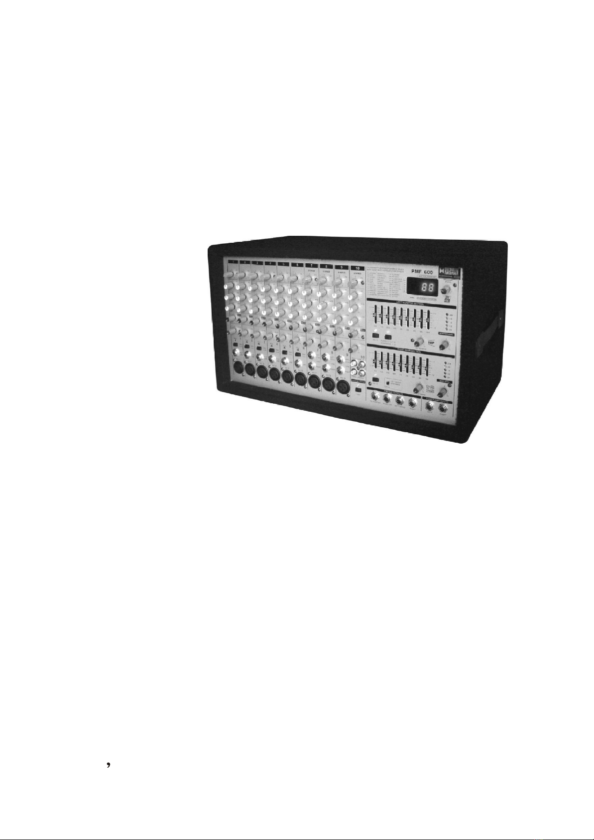
Congratulations! With the PMF600 you have acquired a state-of-the-art 10-channel power
mixer that sets new standards . Right from the start ,our goal has been to design a revolutionary
device that can be used for a great variety of applications . And indeed , this over whelming
power mixer gives you plenty of functionality and a broad range of connection and expansion
options .
1.1 Before you start
Your PMF600 was carefully packed at the factory and the packaging is designed to
protect the unit from rough handling . Nevertheless , we recommend that you carefully
examine the packaging and its contents for any signs of physical damage which may have
occurred during transit .
FIf the unit is damaged , please do NOT return it to HARMAN ,but notify your dealer
and the shipping company immediately . Otherwise ,claims for damage or replacement
may not be granted .
1.1.1 Shipment
1.1.2 Initial operation
Be sure that there is enough space around the unit for cooling and , to avoid overheating
please do not place the PMF600 near radiators etc .
FBefore you connect the PMF600 to the mains , please make sure that the voltage
setting on the unit matches the local voltage !
FIf you set the unit to a different mains voltage , be sure to use a fuse of the correct
type and rating . Please referto the SPECIFICATIONS for details .
FBlown fuses must be replaced by fuses of the same type and rating ! Please refer to
the SPECIFICATIONS for details .
The mains connection is made using the enclosed power cord and a standard IEC receptacle.
It meets all of the international safety certification requirements .
FPlease make sure that all units have a proper ground connection . For your own
safety , never remove or disable the ground conductor from the unit or of the AC
power cord . The unit shall always be connected to the mains socket outlet with a
protective earthing connection .
2. CONTROL ELEMENTS
2.1 Front panel
Your PMF600 comes with ten input channels , which only differ in terms of pad switch ,
peak LED and interface panel . Since the EQ effect ,monitor and level controls are identical
on all channels , they will be described only once on the enclosed sheet .
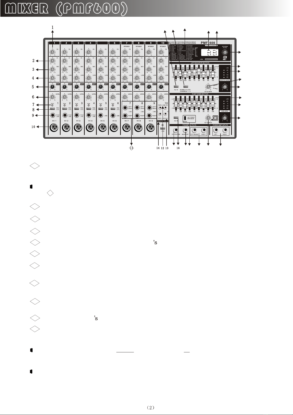
The FX control determines the signal level that is routed from the respective channel
to the built-in effects processor .
1
FPlease note that the effects processor is muted as long as the FX TO MAIN control
( )is set fully counter-clockwise .
22
The HI control in the EQ section governs the high frequencies of the respective channel
2
Use the MID control to boost/cut the mid range .
3
The LOW control allows you to raise or lower the bass frequencies .
4
The MON control determines the channel volume assigned to the monitor mix
5
Use the LEVEL control to set the volume level of the respective channel .
6
Use the PEAK LED to ensure that the input gain is set properly . The PEAK LED
should light up only with peak signals , but never all the time .
7
The PA D button reduces the channel input sensitivity by 25 dB . Thus you can also
connect high-level line signals to the respective channel input .
8
This HI - Z/LINE input can be used to connect line level signal sources , such as
keyboards , electric and bass guitars .
9
This is the channel balanced XLR microphone input .
10
The stereo line input of Channels 7 - 9 can be used to connect , for example keyboards
with stereo outputs or a stereo drum computer .
11
FPlease remember to use either the microphone or the line input on a specific
channel . Never use both at the same time . This rule applies to chanels 1 - 9 .
FWhen you connect a mono line signal to channels 7 - 9 , please always use the left
input . The mono signal will then be reproduced on both stereo sides .
5
IMPIMP
2525 2626 2121 2727 2222 2828
2323
1515
2424
1919
1515
2020
1818
1616 1717 3030
2929
3232
3131

The TAPE/LINE IN RCA input of channel 10 allows you to feed in external stereo
signals from your CD player or tape deck , for example .
12
The TAPE / LINE OUT RCA output provides the stereo main mix signal of your
PMF600 and can be routed to , say , a recording machine .
13
FWhen the TAPE OUT signal is connected to a tape deck whose output signal is
routed back to the TAPE IN on the PMF600 feedback can be produced as soon as
you start recording . Be sure to interrupt the connection to the TAPE IN before
recording !
The phantom power supply provides the voltage necessary for the operation of
condenser microphones . Use the PHANTOM POWER switch to activate the supply
together for channels 1 - 9 (XLR connector) . The LED above the switch is lit when
phantom power is on .
14
This is the PMF600 graphic stereo equalizer which comprises two units and can be used
to adapt the sound to the room acoustics .
15
The stereo equalizer is effective on the main mix when both units have been activated
with the EQ IN buttons and the MODE switch is set to its upper position
( LEFT/RIGHT ) .
16
21
The stereo equalizer use one unit each to process the main and monitor mix
signals if both units are on and the MODE switch is set to its lower position
( MON/MAIN ).
21
Use the EQ IN buttons to switch the two equalizer units on or off .
16
Press the RUMBLE FILTER button to activate the low -cut filter of channels 1-6 . This
filter eliminates unpleasant bass frequencies (e.g. Microphone pop noise)
17
The FX TO MON IN control determines the effects intensity of the multi - effects
processor as part of the monitor mix . Tum the control fully counter-clockwise to add
no effect to the monitor mix .
18
The MONITOR LEVEL control adjusts the volume of the monitor mix .
19
Use the MONITOR LEVEL display to control the monitor signal level . The upper
LED (LIM) lights up when the built-in limiter is activated , thus protecting against
overload .
20
With this MODE switch you can determine whether the PMF600 works as a stereo
amplifier ( LEFT/RIGHT ) or as a dual mono amplifier( MON/MAIN ) . Please
note that the equalizer function also depends on this switch setting (see ) .
21
15
The FX TO MAIN control functions as FX return for the built-in effects processor
Use this control to add the desired effect signal to the main mix . No effect signal is
added when the FX TO MAIN is set fully counter-clockwise .
22
The MAIN LEVEL control governs the overall volume of the PMF600 .
23
The MAIN LEVEL display reads the output level of the PMF600 . The upper LED(LIM)
lights up when the built-in limiter is activated , thus protecting against signal peaks .
24
Use the FX FOOT SWITCH jack to connect any commercially available foot controller
It allows you to bypass the effects unit .
25
This is balanced MONITOR output of your PMF600 . Use it to feed an external monitor
amp or active wedge .
26
These two 1/4 TS jacks allow you to route the output signal to an external amplifier
This allows you to , say , use only the mixing and effect section of the PMF600 . The
signal is taken pre-power amp . Of course , you can also use only the left jack as a
mono output .
27
These two 1/4 TS jacks can be used to connect external signals , such as the main mix
signal from an additional mixing console (pre-power amp ).
28
Here , you will find a list of all multi-effect presets available .
29
This is the LED level meter of the effects processor .Please make sure that the clip LED
lights up with signal peaks only . If it lit constantly , this indicates that the effects
processor is overdrive , which can lead to unpleasant distortion .
30
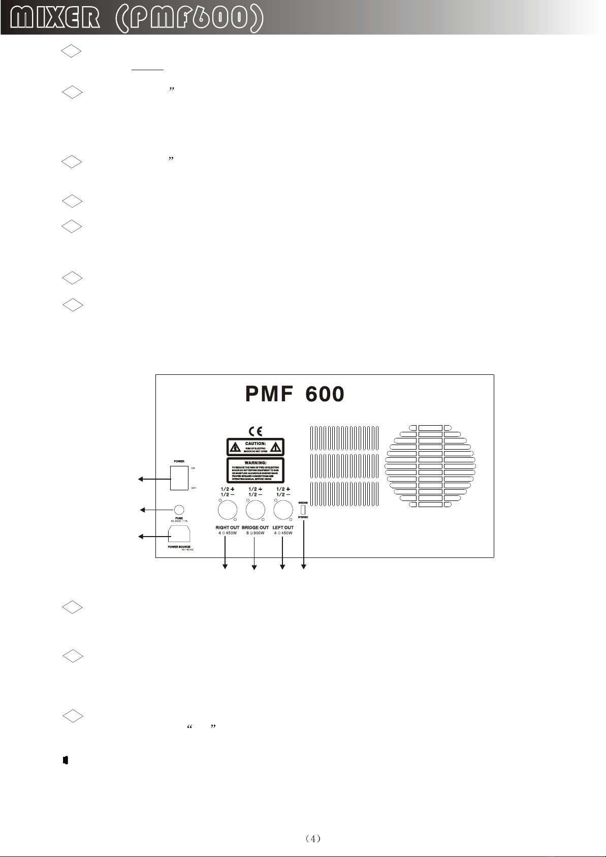
The mains connection is on a standard IEC receptacle . An appropriate power cord is
supplied with the unit .
33
Tum the PROGRAM control to select the effect presets . Press the control briefly to
confirm your selection .
32
2.2 Rear panel
The EFFECT display reads the currently selected preset .
31
FUSE HOLDER Before connecting the unit to the mains ,ensure that the voltage setting
matches your local voltage . Blown fuses should only be replaced by fuses of the same
type and rating .
34
Use the POWER switch to put your PMF600 into operation .The POWER switch should
always be in the off position when you are about to connect your unit to the mains .
35
FAttention : The POWER switch does not fully disconnect the unit from the mains
Unplug the power cord completely when the unit is not used for prolonged periods
of time .
AC 200~240V:AC 200~240V:
3535
3434
3333
3636 3737 3838 3939

FThe impedance of the loudspeaker connected here must not fall below 4 .
This is the RIGHT/MONO MAIN loudspeaker output of your PMF600 . Where you
can connect the right loudspeaker of a stereo system . For this purpose , switch must
be set to its upper position . If however , you run a mono main mix (switch set to its
lower position ) , this loudspeaker output provides the main mix signal in mono .
36
21
21
The BRIDGE loudspeaker output allows you to combine the left and right stereo
channel in one mono output , which is useful for applications that require the use of
one loudspeaker only . To use the BRIDGE output , switch must be set to
LEFT/RIGHT .
37
21
FAlways connect the BRIDGE jack to a loudspeaker with a minimum impedance
of 8 !
FPlease note that the power delivered to the speaker connected to the BRIDGE
output is considerably higher than the power provided to the speakers wired
to the parallel speaker outputs . Please read the information given on the rear
panel of your PMF600 .
FWhen using the BRIDGE loudspeaker output , NEVER use any of the other two
connectors ( RIGHT/MONO MAIN and LEFT/MONITOR ) at the same time !
This is the LEFT/MONITOR loudspeaker output of your PMF600 , to which you can
connect the left loudspeaker of a stereo system ( switch set to its upper position).
If you do a main mix in mono ( switch set to its position ) , this loudspeaker
output provides the monitor signal in mono .
38
21
21
FThe impedance of the loudspeaker connected here must not fall below 4 .
FInformation on how to properly connect your speaker with regard to polarity can
be found on the rear of the unit ( PIN assignment ) .
BRIDGE/STEREO Switch : Mode option when the switch is on BRIDGE,
the mixes is on “BRIDGE” working mode, when in STEREO it is on “ STEREO”
working mode.
39
3. EFFECTS PROCESSOR
A special feature of your PMF600 is its built-in multi-effects processor . The processor
comes with 99 different standard effects such as reverb , chorus , flanger , delay , vocal
distortion as well as various effects combinations .
FX
REVERBREVERB
Cathedral : Simulates the dense , long reverberation of a large cathedral , which is
appropriate for solo instruments or vocals in slow pieces . Please choose between two
variations .

Concert : Here , you can select between a small theater and a large hall . Although this
program is similar to studio ( see below ) it features more presence which adds to its
lively character .
Stage : Is well suited to dissipating the sound of a keyboard or an acoustic guitar .
Room : You can clearly heat the walls of the room . A useful program for reverb that isn
directly noticable ( rap , hip hop vocals ) or to make dry recordings of instruments sound
natural again .
S
Studio : This simulation of a middle to large-sized room is also available in two
variations . Both variations sound very natural . Very all-round effect .
Small Hall : Simulates a small , lively ( strongly reflecting ) hall and is perfect for
processing drums .
Ambience : Reproduces a middle-sized room with out late reflections .
Early Reflections : The initial reflections of this room are clearly audibly . This effect
a classic for dynamic signals ( drums , percussion , slap bass etc . ) .
Spring Reverb : Simulates a classic spring reverberation .
Gated Reverb : This effect synthetically cuts off reverberation after a period of time . It
is famous in the song In the Air Tonight by Phil Collins . The variations differ in the
reverb length .
Revers Reverb : This is a reverberation in which the envelope is reversed-it slowly
gets louder .
FX
MODULATIONMODULATION
Chorus : This effect slightly detunes the original signal . A very pleasant detune effect is
created in connection with the pitch variation . The chorus effect is quite often and
extensively used for dispersing signals - in such a variety of applications that any
recommendation would mean a limitation of their use . The variations available here range
from slow to fast chorus effects .
Symphonic : This effect creates the sound of an eight-person (!) Vocal chorus .
Flanger : The word flange means tape spool ,and this explains the characteristics
of the effect . Originally the flanger effect was generated with two tape recorders which ran
synchronously . The same audio signal was recorded on both machines. If you put a finger on
the left spool of the machines , the spool and the playback speed are slowed down . The
generated delay results in phase shifting of the signals . Please choose either medium
flanger or one of the bright flanger programs , which feature an increase in persence.
Plate : Simulates the sound of plate reverberators and hence is a classic for drums
(snare) and vocals . In comparison with the first variation , the second one features more
high-end sparkle .

Phaser : With the phaser , a second , phase-shifted signal is added to the original audio
signal .This effect is often used for guitar sounds and keyboards . In the 70s, it was also
extensively used for other instruments like electric pianos . The PMF600 offers you four
different phaser variations .
Rotary Speaker : Thesimulation of a classic effect that is normally generated with a
very heavy enclosure comprising ( slow or fast ) rotating speakers .
FX
DELAYDELAY
Delay : A delay of the input signal with various repetitions . Different tempo settings
( ten variations in total ) allow interesting delay effects .
Echo : Similar to the stereo delay , with the difference being that the repetitions have less
presence . This simulates the character of the original tape echo that was used before the digital
era and can be thought of as a Vintage Sound .
Multi Tap : A delay effect with changing stereo positioning . Four variations of reverb .
FX
SERIALSERIAL
Chorus Reverb : This algorithm combines the popular chorus with a reverb effect .
Taking all variations into account , they differ in the length of reverb .
Flanger Reverb : The combination of flanger and reverb effects .
Phaser Reverb: The combination of a classic stereo phaser and a reverb effect . Here
too , the phaser is combined with different reverb types .
Rotary Speaker Reverb: A real classic , the rotary speaker effect , is processed
with a reverb effect . This effect works especially well with keyboards and guitars .
Delay Reverb: Delay and reverb is the most common combination for vocals , solo
guitars , etc .
Pitch Reverb: The pitch shifter slightly detunes the audio signal , while the reverb
adds ambience to the signal .
Delay Chorus: While the chorus can contribute to a wideness of the signal , interesting
repetition effects can be adjusted with the delay . Vocals can be given a distinctive effect
without making the voice sounding blurred .
Delay Flanger : This effect is just right for creating a modem , slightly spacey
vocal sound .
Delay Pitch : A repetition of the audio signal , with an oscillatory effect added by the
pitch shifter .

3-Voice Pitch : The pitch effect can be used to produce a cartoon-character type voice
effect .
FX
SPECIAL FXSPECIAL FX
LFO Bandpass : Filters , in general , influence the frequency response of a signal . A
low-pass filter allows low frequencies to pass and suppresses high frequencies , while a high
pass filter allows high frequencies to pass and suppresses low frequencies . This LFO
bandpass effect is complemented by modulation due to a LFO ( Low Frequency Oscillator) .
Vocal Distortion : This effect is very hip when used on vocals and drum loops .
Vinylizer : This effect adds clicks and noise to your audio signal , simulating old vinyl
records .
Space Radio : Here , the typical sound of scanning an FM tuner is simulated . This can
be very interesting effect when sound-tradking radio plays .
Tes t To ne : Use this 1 kHz test tone to facilitate P. A .level setting .

Specification
Model JF844 JF842 JF666
Mic-60dBm Line-20dBm StereoCH In-20dB Tape In-10dB Aux Send-20dB
8V Max
Less than 0.01%(at 1kHZ)
20Hz-20kHz 2dB
90dB
N/A
Hi 15dB/12kHz Mid 15dB/2.5kHz Low 15dB/80Hz
AC 95-120V 60Hz / AC 220-240V / 50-60Hz
280 460 270
14.5
+22dBu
120
+22dBu
20k balanced/10k unbalanced
+22dBu
240 synm/120 unbalanced
+22dBu
240 synm/120 unbalanced
120dB all Channelsat Unity Gain
AC 95V-120V/60Hz
AC 220V-240V/50-60Hz
24-bot Sigma-Delta
64/128-times oversampling
46-85KHZ
Item
Input Sensitivity
Output Voltage
S/N
THD(1kHz Full Power)
Frequency Response
Headphone
Power Consumption
Parametric EQ
Power Supply
Dimension(H W D)mm
Weight(Kg)
Master Mix Section
Aux sends
Impedance approx
Stereo aux returns
Impedance approx
Main outputs
Impedance approx
Group output
Impedance approx
S/N
Power Supply
DSP
46-85KHZ
Sampling
rate
9
N/A
Table of contents
Other Elmuz Music Mixer manuals


