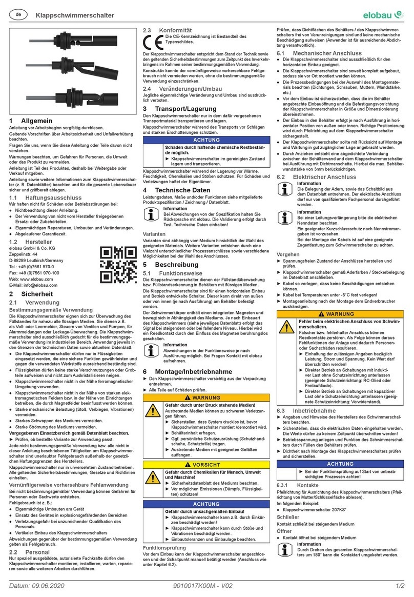
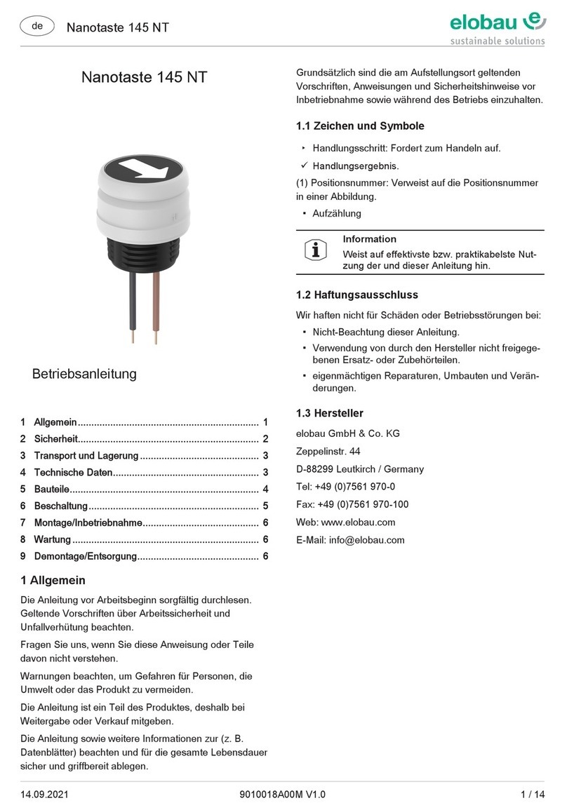
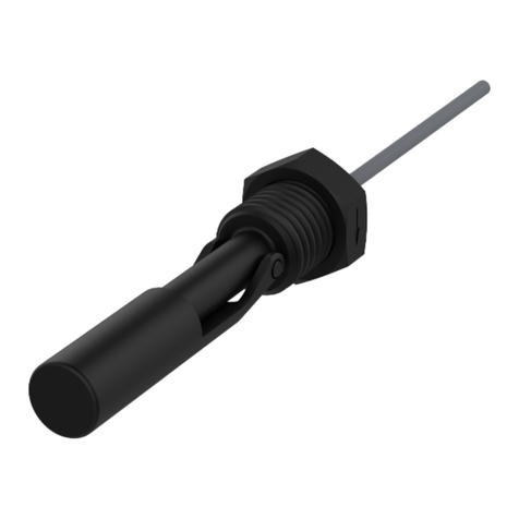
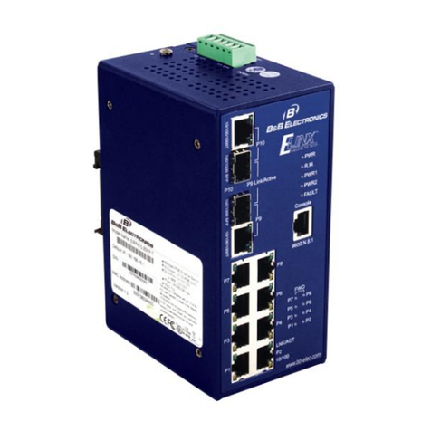
elobau 145NT Series User manual

de
Nanotaste
1 / 6Version 1.025.07.2017
Inhaltsverzeichnis
1 Allgemein................................................................... 1
2 Sicherheit................................................................... 2
3 Transport und Lagerung ............................................ 3
4 Technische Daten...................................................... 3
5 Bauteile...................................................................... 5
6 Beschaltung............................................................... 5
7 Montage / Inbetriebnahme......................................... 6
8 Wartung ..................................................................... 6
9 Demontage / Entsorgung........................................... 6
1 Allgemein
Die Anleitung vor Arbeitsbeginn sorgfältig durchlesen.
Geltende Vorschriften über Arbeitssicherheit und
Unfallverhütung beachten.
Fragen Sie uns, wenn Sie diese Anweisung oder Teile
davon nicht verstehen.
Warnungen beachten, um Gefahren für Personen, die
Umwelt oder das Produkt zu vermeiden.
Die Anleitung ist ein Teil des Produktes, deshalb bei
Weitergabe oder Verkauf mitgeben.
Die Anleitung sowie weitere Informationen zur Nanotaste
(z. B. Datenblätter) beachten und für die gesamte
Lebensdauer sicher und griffbereit ablegen.
Grundsätzlich sind die am Aufstellungsort geltenden
Vorschriften, Anweisungen und Sicherheitshinweise vor
Inbetriebnahme sowie während des Betriebs einzuhalten.
1.1 Zeichen und Symbole
▸ Handlungsschritt: Fordert zum Handeln auf.
üHandlungsergebnis.
(1) Positionsnummer: Verweist auf die Positionsnummer
in einer Abbildung
▪ Aufzählung
i
Information
Weist auf effektivste bzw. praktikabelste Nut-
zung der Nanotaste und dieser Anleitung hin.
1.2 Haftungsausschluss
Wir haften nicht für Schäden oder Betriebsstörungen bei:
▪ Nicht-Beachtung dieser Anleitung.
▪ Der Verwendung von durch den Hersteller nicht frei-
gegebenen Ersatz- oder Zubehörteilen.
▪ Eigenmächtigen Reparaturen, Umbauten und Verän-
derungen.
1.3 Hersteller
elobau GmbH & Co. KG
Zeppelinstr. 44
D-88299 Leutkirch / Germany
Tel: +49 (0)7561 970-0
Fax: +49 (0)7561 970-100
Web: www.elobau.com
E-Mail: [email protected]
Nanotaste
Gebrauchsanweisung

de
Nanotaste
2 / 6 25.07.2017Version 1.0
1.4 Gewährleistung
i
Information
Alle Nanotasten unterliegen vor Auslieferung
einer Funktionskontrolle.
Für dieses Produkt gilt eine Gewährleistung von 24
Monaten ab Kaufdatum.
Defekte, die während dieser Gewährleistungszeit in Form
von Material- und/oder Herstellungsfehlern auftreten,
werden kostenfrei behoben, entweder durch Reparatur
oder durch Ersatzlieferung. Soweit gesetzlich zulässig,
sind andere Ersatzansprüche ausgeschlossen.
Die Gewährleistung entfällt beim Eingreifen Dritter bzw.
bei Demontage von Seiten Dritter ohne unsere vorherige
Zustimmung. Die Gewährleistung entfällt auch bei
willkürlicher Beschädigung oder fehlerhafter
Handhabung.
Bei Erbringung einer Gewährleistung verlängert sich der
Gewährleistungszeitraum nicht.
Für nicht gerechtfertigte Reklamationen, z. B.
Installations- bzw. Bedienungsfehler behalten wir uns das
Recht vor, die entstandenen Kosten in Rechnung zu
stellen.
i
Information
Ohne vollständig ausgefüllte und vorliegende
Unbedenklichkeitsbescheinigung wird die An-
nahme der Reklamation verweigert!
2 Sicherheit
2.1 Verwendung
Bestimmungsgemäße Verwendung
Die Nanotaste 145NT eignet sich für verschiedene
Einsatzbereiche, z. B.:
▪ Einbau in Bedienpanels oder Tastaturfelder.
▪ Einsatz im Fahrzeugbau, Joystickgriffen, … .
Die Umgebungsbedingungen sind vor Einsatz der
Nanotaste vom Anwender zu prüfen.
▪ Die Nanotaste nur im vollständig geschlossenen und
unversehrten Gehäuse betreiben.
▪ Die Nanotaste nur sachgerecht und bestimmungsge-
mäß verwenden. Bei Zuwiderhandlungen erlischt jeg-
liche Garantie und Herstellerverantwortung.
▪ Sicherstellen, dass die Sicherheitsbestimmungen der
einzelnen Maschinen beachtet werden.
▪ Sicherstellen, dass die internationalen und nationalen
Bestimmungen beachtet werden.
▪ Tasten dürfen nicht in ferritischen Materialien mon-
tiert werden.
Vernüftigerweise vorhersehbare Fehlanwendung
Bei nicht bestimmungsgemäßer Verwendung können
Gefahren für Personen oder Sachwerte entstehen.
Fehlgebrauch ist z. B.:
▪ Fall aus Höhen über 1 m. Die Funktion der Nanotaste
ist dadurch nicht mehr gewährleistet.
▪ Technische Daten nicht einhalten.
2.2 Warnhinweise
2.2.1 Signalwörter
In der Anleitung wird die Schwere der Gefahr und deren
Folgen mit dem Signalwort und mit Farben eingestuft.
GEFAHR
Bezeichnet eine unmittelbar drohende Ge-
fahr.
Wenn sie nicht gemieden wird, sind Tod oder
schwerste Verletzungen die Folge.
WARNUNG
Bezeichnet eine möglicherweise gefährli-
che Situation.
Wenn sie nicht gemieden wird, sind Tod oder
schwerste Verletzungen die Folge.
VORSICHT
Bezeichnet eine möglicherweise schädli-
che Situation.
Wenn sie nicht gemieden wird, können leichte
oder geringfügige Verletzungen die Folge
sein.
HINWEIS
Bezeichnet eine möglicherweise schädli-
che Situation.
Wenn sie nicht gemieden wird, können Schä-
den am Produkt oder andere Sachschäden die
Folge sein.
2.2.2 Piktogramme
Diese Piktogramme werden in dieser Anleitung
verwendet, wenn es erforderlich ist.
Warnung vor einer allgemeinen Gefahr.
Dieses Warnzeichen warnt vor Tätigkeiten, bei
denen mehrere Ursachen zu Gefährdungen
führen können.

de
Nanotaste
3 / 6Version 1.025.07.2017
Warnung vor gefährlicher elektrischer
Spannung
Dieses Warnzeichen warnt vor Tätigkeiten, bei
denen die Gefährdungen eines elektrischen
Schlages, eventuell mit tödlichen Folgen, be-
stehen.
2.3 Personal
Nur speziell ausgebildete, autorisierte Fachkräfte dürfen
die Nanotaste montieren, installieren, warten, reparieren
sowie alle weiteren Arbeiten durchführen.
2.4 Konformität
Die Nanotaste entspricht dem Stand der Technik sowie
den geltenden Sicherheitsbestimmungen zum Zeitpunkt
des Inverkehrbringens im Rahmen ihrer
bestimmungsgemäßen Verwendung.
Konstruktiv konnte der vernünftigerweise vorhersehbare
Fehlgebrauch vermieden werden, ohne die
bestimmungsgemäße Funktionalität einzuschränken.
2.5 Veränderungen und Umbau
Jegliche eigenmächtige Veränderung und Umbau sind
ausdrücklich verboten.
3 Transport und Lagerung
Die Nanotaste während der Lagerung vor Wärme,
Feuchtigkeit, Chemikalien und Stößen schützen.
4 Technische Daten
4.1 Bezeichnung/Typenschlüssel
Artikelnummer Nanotaste:
1-3 4-5 6 7 8 9-10 Hinweis
145 NT Nanotaste
GGewindege-
häuse und
Reedschalter
HGewindege-
häuse und Hall
Switch
0keine LED’s
1eine LED
2zwei LED’s
0Open Drain
(Hall Switch)
Schließer N/O
(Reedschalter)
1High Side
(Hall Switch),
Namurbeschaltung
(Reedschalter)
xx Codierung
Farbeinleger

de
Nanotaste
4 / 6 25.07.2017Version 1.0
4.2 Abmessungen
4.3 Einbaumaße
Durchmesser: 15 mm
Höhe: 15,85 mm
Einbaugewinde: M12x1
4.4 Mechanische Kennwerte
Lebensdauer: 2 Mio. Schaltspiele
Betätigungskraft: ca. 7 N
Betätigungsweg: 2,15 mm
Hysterese: typ. 0,25 mm
Schock: beständig gemäß DIN EN
60068-2-27
Vibration: beständig gemäß DIN EN
60068-2-6
4.5 Anschlussart
Litzenlänge, standardisiert: Lify 500 mm ± 30 mm, Ø
0,1 mm²
4.6 Elektrische Kennwerte
Schaltspannung: Max. 30 V AC/DC
Schaltstrom: Max 0,3 A/DC
Schaltleistung: Max. 3 W/VA
Betriebsspannung LED: Typisch 5 V, 12 V, 24V
(abhängig vom
Vorwiderstand)
Betriebsspannung
(Hall Switch):
5 V +/- 10 %
Stromaufnahme
(Hall Switch):
max. 2,5 mA
MTTF (Reedschalter): 2111 Jahre (ohne LED)
436 Jahre (mit LED)
MTTF (Hall Switch): 296,24 Jahre (ohne LEDs)
217,30 Jahre (mit LEDs)
EMV-Beständigkeit
(Reedschalter):
gemäß
ISO 7637-3:2007
ISO 7637-3:200
ISO 10605:2008
ISO 16750-2:2012
EMV-Beständigkeit
(Hall Switch):
gemäß
DIN EN 14982:2009
DIN EN 55025:2009
ISO 11452-2:2004
ISO 11452-4:2005
ISO 11452-5:2002
ISO 11452-8:2015
ISO 7637-3:2007
ISO 10605:2008

de
Nanotaste
5 / 6Version 1.025.07.2017
4.7 Sonstige Angaben
Arbeitstemperaturbereich: -40°C…+85°C
Lagertemperaturbereich: -40°C…+85°C
Schutzart Elektronik: IP 67 DIN EN 60529
Schutzart Betätigungsseite
(im eingebauten Zustand):
IP 65 DIN EN 60529
UV-Beständigkeit: gemäß DIN EN 60068-2-5
4.8 Chemische Beständigkeit
+ Getriebeöl + Motoröl + Diesel
+ Biodiesel + Batteriesäure +Reinigungsmittel
+ Benzin + Kühlflüssigkeit + handelsübliche
Getränke
5 Bauteile
5.1 Gehäuse
Nanogehäuse
5.2 Mutter
Mutter SW17, M12x1
Rändelmutter M12x1
5.3 Drücker
Standarddrücker transparent – diffus für Farbeinleger
2-Komponenten-Drücker mit Haptik, konvex
2-Komponenten-Drücker mit Haptik, flach
2-Komponenten-Drücker mit Haptik, konkav
5.4 Beleuchtung
Beleuchtung für Funktions- und / oder Nachtbeleuchtung.
Ansteuerbare LED Farben:
rot weiß grün
gelb blau orange
5.5 Farbeinleger
1
Farbeinleger (1) mit Ø 12 mm sind gemäß Katalog als
Standard beziehbar. Jede andere RAL-Farbe ist nach
Rücksprache möglich und im Datenblatt definiert.
5.6 Symbole
Symbole können gemäß dem Standard der ISO 7000
aufgedruckt werden.
Die Einleger werden hinterdruckt und sind vor Abrieb
geschützt. Der beleuchtete Durchmesser der
Betätigungskappe beträgt 10 mm.
6 Beschaltung
Standardschaltbilder beispielhaft- maßgeblich ist die im
Datenblatt angegebene Schaltung
Schließerkontakt

de
Nanotaste
6 / 6 25.07.2017Version 1.0
Reedschalter
Namur-
beschaltung
LED 1 Funktionsbeleuchtung, LED 2 Nachtbeleuchtung
Hall Switch, „open drain“ schaltend
Hall Switch, „low side“ schaltend
Hall Switch, „high side“ schaltend
Maßgeblich sind die im Datenblattdiagramm
angegebenen Ausgangssignale in Abhängigkeit des
Lastwiderstands (in den technischen Daten sind die
Angaben standardmäßig bei 10kΩ erfolgt).
7 Montage / Inbetriebnahme
HINWEIS
Gefahr durch falsche Anschlusswerte.
Beschädigung der Nanotaste.
Elektrische Daten einhalten.
Stellen Sie diese Anleitung den Personen zur Verfügung,
die die Nanotaste installieren, warten und bedienen.
ØSicherstellen, dass die Nanotaste nur von speziell
ausgebildetem, autorisiertem Personal montiert wird.
1. Die Nanotaste auf einer ebenen Fläche (mechanisch
spannungsfrei) montieren.
ðNanotaste in die Einbauöffnung stecken und mit
der Mutter kontern.
2. Die Nanotaste anschließen.
7.1 Anschluss
Die Litzenabgänge können je nach Erfordernissen mit
Stecker (Molex, AMP, …) bestückt werden.
i
Information
Polarität der LED-Anschlüsse beachten. Bei
falscher Polung leuchtet die LED nicht.
8 Wartung
Die Nanotaste ist wartungsfrei.
9 Demontage / Entsorgung
9.1 Demontage
ØSpannungsfreien Zustand herstellen.
▸ Nanotaste demontieren.
üNanotaste ist demontiert.
9.2 Entsorgung
Verpackung und verbrauchte Teile gemäß den jeweiligen
Landesvorschriften entsorgen. Die Nanotaste getrennt
vom Hausmüll, z. B. bei einer Sammelstelle eines
Entsorgungsträgers, entsorgen.

en
Nano push-button
1 / 6version 1.008.08.2017
Table of Contents
1 General Points........................................................... 1
2 Safety ........................................................................ 2
3 Transport and Storage............................................... 3
4 Technical Specifications ............................................ 3
5 Components .............................................................. 4
6 Wiring ........................................................................ 5
7 Assembly / Commissioning ....................................... 6
8 Maintenance .............................................................. 6
9 Disassembly / Disposal ............................................. 6
1 General Points
Read the manual carefully before beginning work.
Observe the valid health and safety regulations.
If you do not understand this manual or parts thereof,
please contact us.
Observe warnings in order to avoid dangers to persons,
the environment or the product.
The manual is part of the product and should therefore
be included in the case of transfer or sale.
Observe the manual and further information on the nano
push-button (e.g. data sheets) and store in a safe,
accessible place throughout the useful life.
The regulations, instructions and safety information valid
at the place of installation are always to be observed
before commissioning and during operation.
1.1 Icons and Symbols
▸ Operating step: Requires an action.
üResult of action.
(1) Item number: Refers to the item number in a diagram
▪ List
i
Information
Indicates the most effective or most practical
use of the nano push-button and of these in-
structions.
1.2 Disclaimer
We are not liable for damage or operational faults in the
event of:
▪ failure to observe this manual.
▪ use of replacement and accessory parts not author-
ised by the manufacturer.
▪ unauthorised repairs, conversions and modifications.
1.3 Manufacturer
elobau GmbH & Co. KG
Zeppelinstr. 44
D-88299 Leutkirch / Germany
Phone +49 (0)7561 970-0
Fax: +49 (0)7561 970-100
Web: www.elobau.com
Mail: [email protected]
Nano push-button
Translation of the original operating
manual

en
Nano push-button
2 / 6 08.08.2017version 1.0
1.4 Warranty
i
Information
All nano push-buttons are subject to a func-
tional inspection before delivery.
This product is covered by a warranty of 24 months from
date of purchase.
Defects occurring within this warranty period in the form
of material and/or production faults will be rectified free of
charge, either by means of repair or replacement. Insofar
as legally permitted, other claims for compensation are
excluded.
The warranty is rendered null and void in the event of
interventions by third parties or disassembly by third
parties without our prior permission. The warranty is also
rendered null and void in the event of wilful damage or
incorrect handling.
Provision of a service under warranty does not extend
the warranty period.
In the case of unjustified complaints, e.g. installation or
operating faults, we reserve the right to charge the costs
incurred.
i
Information
We shall refuse to accept the complaint
without a clearance certificate!
2 Safety
2.1 Application
Use as intended
The nano push-button 145NT is suitable for various
areas of application, e. g.:
▪ installation in control panels or keypads.
▪ use in vehicle manufacture, joystick handles, … .
The environmental conditions are to be checked by the
user before using the nano push-button.
▪ Only operate the nano push-button in the completely
sealed, undamaged housing.
▪ Only use the nano push-button correctly and for its in-
tended purpose. In the event of infringement, all war-
ranty claims and responsibility of the manufacturer
are excluded.
▪ Ensure that the safety regulations of the individual
machines are observed.
▪ Ensure that the national and international regulations
are observed.
▪ Keys must not be installed in ferritic materials.
Reasonably predictable incorrect use
Improper use may constitute dangers to persons and
property.
Improper use is, e. g.:
▪ fall from heights of more than 1 m. Operation of the
nano push-button is then no longer guaranteed.
▪ failure to observe technical specifications.
2.2 Warning Signs
2.2.1 Key Words
In the instructions, the seriousness of the danger and its
consequences are classified by the key word and with
colours.
DANGER
Designates an imminent danger.
If it is not avoided, the consequence is death
or very serious injury.
WARNING
Indicates a possible danger.
If it is not avoided, the consequence is death
or very serious injury.
CAUTION
Designates a potentially dangerous situ-
ation.
If it is not avoided, the consequence may be
slight or minor injury.
NOTE
Designates a potentially dangerous situ-
ation.
If it is not avoided, the consequence may be
damage to the product or other property.
2.2.2 Pictograms
These pictograms are used in these instructions where
necessary.
Warning of a general danger.
This warning sign warns against activities
where several causes may lead to dangers.
Warning of hazardous electrical voltage
This warning sign warns against activities
where there is a risk of an electric shock with
potentially fatal consequences.

en
Nano push-button
3 / 6version 1.008.08.2017
2.3 Personnel
Only specially trained, authorised specialists may
assemble, install, maintain, repair and carry out all other
work on the nano push-button.
2.4 Conformity
The Nanotaste complies with latest technical standards
and the valid safety regulations at the time of being
placed in the stream of commerce for its intended use.
For design reasons, it was not possible to reasonably
prevent foreseeable misuse without restricting the
intended use.
2.5 Modifications and Conversions
All unauthorised modifications and conversions are
strictly prohibited.
3 Transport and Storage
Protect the nano push-button against heat, humidity,
chemicals and shocks during storage.
4 Technical Specifications
4.1 Designation/type key
Article No. nano push-button:
1-3 4-5 6 7 8 9-10 Note
145 NT nano push-button
GThreaded
housing and reed
switch
HThreaded
housing and Hall
switch
0no LEDs
1one LED
2two LEDs
0Open Drain
(Hall switch)
Normally open N/O
(reed switch)
1High side
(Hall switch),
Namur wiring (reed
switch)
xx Coding colour insert
4.2 Dimensions
4.3 Installation Dimensions
Diameter: 15 mm
Height: 15.85 mm
Installation thread: M12x1

en
Nano push-button
4 / 6 08.08.2017version 1.0
4.4 Mechanical Parameters
Lifetime: 2 m switching cycles
Actuating force: approx. 7 N
Actuating travel: 2.15 mm
Hysteresis: Typ. 0.25 mm
Shock: resistant pursuant to DIN
EN 60068-2-27
Vibration: resistant pursuant to DIN
EN 60068-2-6
4.5 Connection type
Braid length, standardised: Lify 500 mm ± 30 mm, Ø
0.1 mm²
4.6 Electrical Parameters
Switching voltage: Max. 30 V AC/DC
Switching current: Max 0.3 A/DC
Switching capacity: Max. 3 W/VA
Operating voltage LED: Typically 5 V, 12 V, 24V
(depending on pre-
resistance)
Operating voltage
(Hall switch):
5 V +/- 10 %
Power consumption
(Hall switch):
max. 2,5 mA
MTTF (reed switch): 2111 years (without LED)
436 years (with LED)
MTTF (Hall switch): 296.24 years (without
LEDs)
217.30 years (with LEDs)
EMC resistance (reed
switch):
pursuant to
ISO 7637-3:2007
ISO 7637-3:200
ISO 10605:2008
ISO 16750-2:2012
EMC resistance
(Hall switch):
pursuant to
DIN EN 14982:2009
DIN EN 55025:2009
ISO 11452-2:2004
ISO 11452-4:2005
ISO 11452-5:2002
ISO 11452-8:2015
ISO 7637-3:2007
ISO 10605:2008
4.7 Other information
Working temperature
range:
-40°C…+85°C
Storage temperature
range:
-40°C…+85°C
Protection class electronic
system:
IP 67 DIN EN 60529
Protection class actuation
side (when installed):
IP 65 DIN EN 60529
UV resistance: pursuant to DIN EN
60068-2-5
4.8 Chemical resistance
+ Gear oil + Engine oil + Diesel
+ Biodiesel + Battery acid +Detergents
+ Petrol + Cooling fluid + commercially
available beverages
5 Components
5.1 Housing
Nano housing
5.2 Nut
Nut SW17, M12x1
Knurled nut M12x1
5.3 Pusher
Standard push-button transparent – diffuse for colour
insert

en
Nano push-button
5 / 6version 1.008.08.2017
2-component push-button with haptics, convex
2-component push-button with haptics, flat
2-component push-button with haptics, concave
5.4 Lighting
Lighting for functional and / or night lighting.
Controllable LED colours:
red white green
yellow blue orange
5.5 Colour inserts
1
Colour inserts (1) with Ø 12 mm can be purchased as
standard according to the catalogue. Every other RAL
colour is available on request and defined in the data
sheet.
5.6 Icons
Icons can be printed on according to the standard of ISO
7000.
The inserts are back printed and protected against
abrasion. The lit diameter of the actuation cap is 10 mm.
6 Wiring
Standard circuit diagrams as examples- the circuit given
in the data sheet is authoritative
Normally open contact
Reed switch
Namur
wiring
LED 1 Functional lighting, LED 2 Night lighting
Hall switch,”open drain” toggling
Hall switch, “low side” toggling

en
Nano push-button
6 / 6 08.08.2017version 1.0
Hall switch, “high side” toggling
The output signals given in the data sheet diagram
depending on the load resistance (in the technical data,
the values are given as standard at 10kΩ).
7 Assembly / Commissioning
NOTE
Danger due to incorrect connected loads.
Damage to the nano push-button.
Observe electrical specifications.
Make these instructions available to the persons who
install, maintain and operate the nano push-button.
ØEnsure that the nano push-button is only installed by
trained, authorised personnel.
1. Assemble the nano push-button on a level surface
(free of mechanical torsion).
ðInsert the nano push-button into the installation
opening and counter with the nut.
2. Connect the nano push-button.
7.1 Connection
If required, the braid outlets can be equipped with plugs
(Molex, AMP, …).
i
Information
Observe polarity of the LED connections. If the
polarity is incorrect, the LED is not lit.
8 Maintenance
The nano push-button is maintenance-free.
9 Disassembly / Disposal
9.1 Disassembly
ØDisconnect from voltage.
▸ Disassemble nano push-button.
üThe nano push-button is disassembled.
9.2 Disposal
Dispose of packaging and used parts in accordance with
the relevant national regulations. Dispose of the nano
push-button separately from domestic waste, e.g. at a
collection point of a disposal company.
Other manuals for 145NT Series
1
This manual suits for next models
2
Table of contents
Languages:
Other elobau Switch manuals
