Montage- und Betriebsanleitung
Installation and Operating Instructions
Mode d´emploi
Instrucciones de montaje de servicio
Istruzioni per l´uso
Montage- en bedieningshandleiding
SSM/A, SSM/U
SafeKey-Schaltmodul
SafeKey Switching Module
Module commutation SafeKey
Módulo interruptor SafeKey
Modulo di commutazione per SafeKey
Safekey Schakelmodule
Einbruchmeldetechnik
2CDG 941 085 P0001
1
DE
EN
FR
IT
NL
ABB STOTZ-KONTAKT GmbH
Eppelheimer Straße 82, 69123 Heidelberg,
Germany
v+49 (0) 6221 701 607
6+49 (0) 6221 701 724
www.abb.com/knx
Technische Helpline / Technical Support
v+49 (0) 6221 701 434
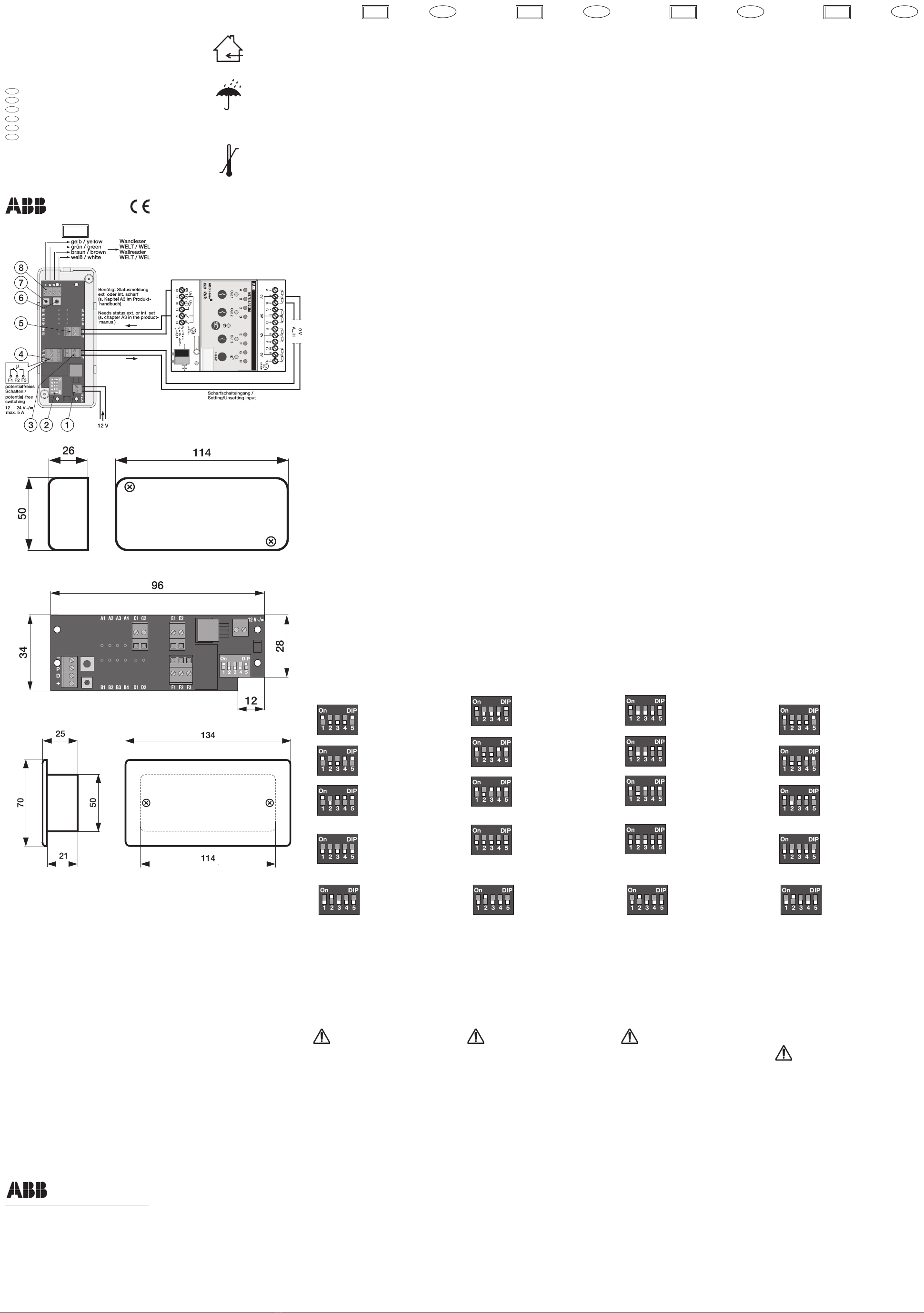
aVersorgungsspannung 12 V DC/AC
bDIP-Schalter
cAusgang E zur Scharf-/Unscharfanforderung
dAusgang F zum potentialfreien Schalten
e Quittierungseingang C
fProgrammiertaster
g Drehpotentiometer
hAnschluss SafeKey-Wandleser (+ / D / P / -)
Gerätebeschreibung
Das SafeKey-Schaltmodul ermöglicht die einfache
Anbindung und Auswertung eines SafeKey-Wandlesers
mit oder ohne Code-Tastatur (WEL od.WELT). Das Modul
kann entweder zum potentialfreien Schalten von elekt-
rischen Komponenten bis 5 A bei max. 12-24 V DC/AC,
z.B. elektrische Türöffner oder Garagentore, oder zum
Weiterleiten einer Scharf-/ Unscharfanforderung an das
Sicherheitsterminal MT/x verwendet werden.
Die Scharf-/Unscharfanforderung kann wahlweise über
Chipschlüssel und/ oder Code-Eingabe eingeleitet wer-
den. Das Gerät ist je nach Gehäuseart für die Unter- bzw.
Aufputzmontage geeignet. Eine 12 V Versorgungsspan-
nung wird benötigt, z.B. NTU/S 12.2000.1.
DE EN FR
Modul-Funktionalität
Die Modul-Funktionalität ist über einen DIP-Schalter
einstellbar. Dabei können folgende Funktionen
eingestellt werden:
Funktion Scharf- / Unscharfanforderung
DIP 1 (ON) : Scharf-/Unscharfanforderung
DIP 2 (OFF) : keine Funktion
DIP 3 (OFF) : Direkte Scharfschaltung
DIP 4 (OFF) : StatischeAnsteuerung des Relais
DIP 5 (ON): IntegrierteWiderstandskombination
DIP 1 (ON): Scharf-/Unscharfanforderung
DIP 2 (OFF): keine Funktion
DIP 3 (OFF): Direkte Scharfschaltung
DIP 4 (ON): DynamischeAnsteuerung des Relais
DIP 5 (ON): IntegrierteWiderstandskombination
DIP 1 (ON): Scharf-/Unscharfanforderung
DIP 2 (OFF): keine Funktion
DIP 3 (ON): Verzögerte Scharfschaltung
DIP 4 (ON): DynamischeAnsteuerung des Relais
DIP 5 (ON): IntegrierteWiderstandskombination
Funktion potentialfreies Schalten
DIP 1 (OFF): potentialfreies Schalten
DIP 2 (OFF):Ansteuerungszeit Relais 1…10 s
(Feinjustierung über Drehpotentiometer)
DIP 3 (OFF): keine Funktion
DIP 4 (OFF): keine Funktion
DIP 5 (OFF): keine Funktion
DIP 1 (OFF): potentialfreies Schalten
DIP 2 (ON):Ansteuerungszeit Relais 10…100 s
(Feinjustierung über Drehpotentiometer)
DIP 3 (OFF): keine Funktion
DIP 4 (OFF): keine Funktion
DIP 5 (OFF): keine Funktion
Montage
Das Gerät ist je nach Gehäuseart für die Unter- bzw.
Aufputzmontage geeignet. Die Zugänglichkeit des
Gerätes zum Betreiben, Prüfen, Besichtigen, Warten
und Reparieren muss sichergestellt sein.
Anschluss
Der elektrische Anschluss erfolgt über Schraubklemmen.
Die Klemmenbezeichnungen befinden sich auf dem Modul.
Inbetriebnahme
Das Gerät ist betriebsbereit,nachdem der SafeKey-Wandleser
und die Versorgungsspannung angeschlossen wurden.
Wichtige Hinweise
Montage und Inbetriebnahme dürfen nur von Elektrofach-
kräften ausgeführt werden. Bei der Planung und Errichtung
von elektrischen Anlagen sind die einschlägigen Normen,
Richtlinien,Vorschriften und Bestimmungen zu beachten.
- Gerät bei Transport, Lagerung und im Betrieb vor
Feuchtigkeit, Schmutz und Beschädigung schützen!
- Gerät nur innerhalb der spezifizierten technischen
Daten betreiben!
- Gerät nur im geschlossenen Gehäuse betreiben!
Reinigen
Verschmutzte Geräte können mit einem trockenenTuch
oder ein mit Seifenlösung leicht angefeuchtetem Tuch
gereinigt werden. Auf keinen Fall dürfen ätzende Mittel
oder Lösungsmittel verwendet werden.
Wartung
Das Gerät ist wartungsfrei. Bei Schäden (z.B. durch
Transport, Lagerung) dürfen keine Reparaturen vorge-
nommen werden.
Bei Beschädigung des Gerätes erlischt der Gewährlei-
stungsanspruch.
1 1 1
Technische Daten (Auszug)
Versorgungsspannung 12 V DC /AC ± 1,6 V
Stromaufnahme < 5 mA (typisch) max. 50 mA
bei Relaisansteuerung
Eingänge
Anzahl 2
SafeKey-Wandleser-
Anschluss + / D / P / -
Quittierungseingang C potentialfrei oder
max. 12 V DC
Klemme C1: +
Klemme C2: -
Ausgänge
Anzahl 2
Typ monostabiles Relais
Ausgang E
Zur Scharf-/Unscharfanforderung mit integrierter
Widerstandskombination (2,7 KOhm + 560 Ohm)
Ausgang F
Zum potentialfreien Schalten elektrischer Komponenten
- max. Schaltstrom
(Ausgang F) max. 5A
- max. Schaltspannung
(Ausgang F) 12 - 24 V DC/AC
Bedienelemente
Programmiertaster
Zum Anlegen des Programmierschlüssels / Löschen
des Schlüsselspeichers
Drehpotentiometer
Zum Feinjustieren der Relais- Ansteuerungszeit bei
der Funktion potentialfreies Schalten
DIP-Schalter
Zur Auswahl der Modul-Funktionalität
Anschlusstechnik
Anschlussklemmen 0,2…1,5 mm2feindrahtig
0,2…1,5 mm2eindrahtig
Anziehdrehmoment max. 0,25 Nm
Temperaturbereich
im Betrieb -5°C…+45°C
Lagerung -25°C…+55°C
Transport -25°C…+70°C
max. Feuchte 93%, keine Betauung
Schutzart IP 30 nach DIN EN 60529
Schutzklasse II nach DIN EN 61140
Abmessung in mm (HxBxT)
Gehäuse AP 50x114x26
Gehäuse UP 50x114x21
Deckel UP 70x134x4
aSupply voltage 12 V DC/AC
bDIP switch
cOutput E for setting/unsetting request
dOutput F for potential-free switching
e Acknowledgement input C
fProgramming key
g Rotary potentiometer
hConnection of SafeKey Wall Reader (+ / D / P / -)
Description of device
The SafeKey switching module makes possible the
simple connection and evaluation of a SafeKey Wall
Reader with or without Keypad (WEL or WELT). The
module can used either for potential-free switching of
electrical components up to 5 A at maximum 12-24 V
DC/AC, such as electric door openers or garage doors,
or for transferring setting/unsetting requests to the MT/x
Security Terminal.
The setting/unsetting request can be initiated selectively
via a chipkey and/or the entry of a code. Depending on
the housing the device is suitable for flush-mounting
or surface-mounting. A 12 V supply voltage is required,
e.g. NTU/S 12.2000.1.
Module function
The function of the module can be set via a DIP switch.
The following functions can be set:
Setting/unsetting request
DIP 1 (ON): Setting/unsetting request
DIP 2 (OFF): No function
DIP 3 (OFF): Direct setting
DIP 4 (OFF): Static activation of relay
DIP 5 (ON): Integrated resistance combination
DIP 1 (ON): Setting/unsetting request
DIP 2 (OFF): No function
DIP 3 (OFF): Direct setting
DIP 4 (ON): Dynamic activation of relay
DIP 5 (ON): Integrated resistance combination
DIP 1 (ON): Setting/unsetting request
DIP 2 (OFF): No function
DIP 3 (ON): Delayed setting
DIP 4 (ON): Dynamic activation of relay
DIP 5 (ON): Integrated resistance combination
Potential-free switching function
DIP 1 (OFF): Potential-free switching
DIP 2 (OFF): Relay activation time 1...10 s
(fine adjustment via rotary potentiometer)
DIP 3 (OFF): No function
DIP 4 (OFF): No function
DIP 5 (OFF): No function
DIP 1 (OFF): Potential-free switching
DIP 2 (ON): Relay activation time 10...100 s
(fine adjustment via rotary potentiometer)
DIP 3 (OFF): No function
DIP 4 (OFF): No function
DIP 5 (OFF): No function
Installation
Depending on the housing the device is suitable for
flush-mounting or surface-mounting. Make sure that
the unit can be accessed at all times for operation,
examination, inspection, maintenance and repair.
connection
The electrical connections are made via screw terminals.
The terminal identification can be found on the module.
Start-up
The unit is ready for operation after the SafeKey Wall
Reader and the power supply have been connected.
Important notes
Installation and commissioning of the device may only be
carried out by qualified electricians. Please comply with
all the relevant standards, guidelines, rules and regula-
tions when planning and setting up electrical installations.
- Protect the unit against humidity, dirt and damage
during transport, storage and operation!
- Always operate the device within the specified techni-
cal data!
- The device may only be operated in closed enclosures!
Cleaning
Soiled units can be cleaned with a dry cloth or with a
cloth that is slightly moistened with a soap solution. Do
not use corrosive agents or solvents.
Maintenance
The unit is maintenance-free. Do not carry out any
repairs when the unit is damaged (e.g. during transport,
storage).
Damaging the unit voids the warranty.
Technical data (excerpt)
Supply voltage 12 V DC /AC ± 1.6 V
Current consumption < 5 mA (typical) max. 50 mA
for relay activation
Inputs
Number 2
SafeKey wall-mounted reader
connection + / D / P / -
Acknowledgement input C potential-free or
max. 12 V DC
Terminal C1: +
Terminal C2: -
Outputs
Number 2
Type Monostable relay
Output E
For setting/unsetting request with integrated resist-
ance combination (2.7 KOhm + 560 KOhm)
Output F
For potential-free switching of electrical components
- max. switching current
(Output F) max. 5 A
- max. switching voltage
(Output F) 12 - 24 V DC/AC
Control elements
Programming key
For creating the programming key / deleting the key
memory
Rotary potentiometer
For fine adjusting the relay activation time of the
potential-free switching function
DIP switch
For selecting the module function
Connection
Connecting terminals 0.2…1.5 mm2, fine-wire
0.2…1.5 mm2, single-wire
Tightening torque max. 0.25 Nm
Temperature range
During operation -5°C…+45°C
Storage -25°C…+55°C
Transport -25°C…+70°C
Maximum humidity 93%, no condensation
Protection IP 30 in acc. DIN EN 60529
Safety class II in acc. DIN EN 61140
Dimensions in mm (HxWxD)
Housing, SM 50x114x26
Housing, FM 50x114x21
Cover, FM 70x134x4
aTension d'alimentation 12 V c.c./c.a.
bInterrupteur DIP
cSortie E pour demande de réglage en alerte/pas en alerte
dSortie F pour la commutation sans potentiel
e Entrée d'acquittement C
fTouche de programmation
g Potentiomètre rotatif
hRaccordement du lecteur mural SafeKey (+ / D / P / -)
Description de l'appareil
Le module commutation SafeKey permet de raccorder et
d'évaluer facilement un lecteur mural SafeKey avec ou sans
clavier de saisie de code (WEL ou WELT). Le module peut
servir à la commutation sans potentiel des composants
électriques jusqu'à 5 A avec une alimentation max. 12-24
V c.c./c.a., par ex. un système électrique d'ouverture de
porte /un portail de garage, ou à transférer une demande
de réglage en alerte/pas en alerte au terminal de sécurité
MT/x.La demande de réglage en alerte/pas en alerte peut,
au choix,être réalisée via une clé à puce et/ou la saisie d'un
code.En fonction du type de bâtiment,l'appareil est adapté
à un montage encastré ou apparent. Une alimentation
électrique 12 V est nécessaire, par ex. NTU/S 12.2000.1.
Fonctionnalité du module
La fonctionnalité du module est réglable via un interrupteur
DIP. Il est ainsi possible de régler les fonctions suivantes:
Fonction Demande de réglage en alerte/pas en alerte
DIP 1 (ON): demande de réglage en alerte/pas en alerte
DIP 2 (OFF): aucune fonction
DIP 3 (OFF): commutation en alerte directe
DIP 4 (OFF): commande statique du relais
DIP 5 (ON):combinaison de résistances intégrée
DIP 1 (ON): demande de réglage en alerte/pas en alerte
DIP 2 (OFF): aucune fonction
DIP 3 (OFF): commutation en alerte directe
DIP 4 (ON): commande dynamique du relais
DIP 5 (ON):combinaison de résistances intégrée
DIP 1 (ON): demande de réglage en alerte/pas en alerte
DIP 2 (OFF): aucune fonction
DIP 3 (ON):commutation en alerte temporisée
DIP 4 (ON): commande dynamique du relais
DIP 5 (ON):combinaison de résistances intégrée
Fonction de commutation sans potentiel
DIP 1 (OFF): commutation sans potentiel
DIP 2 (OFF): temps de commande du relais 1…10 s
(ajustement via un potentiomètre rotatif)
DIP 3 (OFF): aucune fonction
DIP 4 (OFF): aucune fonction
DIP 5 (OFF): aucune fonction
DIP 1 (OFF): commutation sans potentiel
DIP 2 (ON):temps de commande du relais 10…100 s
(ajustement via un potentiomètre rotatif)
DIP 3 (OFF): aucune fonction
DIP 4 (OFF): aucune fonction
DIP 5 (OFF): aucune fonction
Montage
En fonction du type de bâtiment, l'appareil est adapté à
un montage encastré ou apparent. L'accès à l'appareil
doit être possible pour son utilisation, son contrôle, son
inspection, sa maintenance et sa réparation.
Raccordement
Le raccordement électrique s'effectue à l'aide de bornes
à vis. La description des bornes se trouve sur le module.
Mise en service
L'appareil est prêt à fonctionner une fois le lecteur mural
SafeKey et l'alimentation électrique raccordés.
Remarques importantes
Le montage et la mise en service ne doivent être effectués que
par des électrotechniciens. Lors de la planification et de la mise
en place des installations électriques, il convient de respecter les
normes,directives, réglementations et prescriptions applicables.
- Protéger l'appareil contre l'humidité, la poussière
et tout endommagement lors de son transport, son
stockage et son utilisation !
- Utiliser l'appareil uniquement dans les limites spé-
cifiées dans les caractéristiques techniques.
- Utiliser l'appareil uniquement dans un boîtier fermé.
Nettoyage
Les appareils salis peuvent être nettoyés avec un chiffon
sec ou légèrement humidifié à l'aide d'une solution
savonneuse. N'utiliser en aucun cas des produits
corrosifs ou des solvants.
Maintenance
Cet appareil ne nécessite pas de maintenance. En cas
de dommages (par ex. lors du transport, du stockage),
aucune réparation ne doit être entreprise.
La garantie est annulée si l'appareil est endommagé !
Caractéristiques techniques (extrait)
Tension d'alimentation 12 V c.c ./c.a. ± 1,6 V
Consommation électrique < 5 mA (type) max.50 mA
en cas de commande relais
Entrées
Nombre 2
Raccordement du lecteur
mural SafeKey + / D / P / -
Entrée d'acquittement C sans potentiel ou
12 V c.c. max.
Borne C1 : +
Borne C2 : -
Sorties
Nombre 2
Type Relais monostable
Sortie E
Pour une demande de réglage en alerte/pas en alerte
avec combinaison de résistances intégrée (2,7 KOhm
+ 560 Ohm)
Sortie F
Pour la commutation sans potentiel de composants
électriques
- courant de commutation
max. (sortie F) 5 A max.
- Tension de commutation
max. (sortie F) 12 - 24 V c.c./c.a.
Eléments de commande
Touche de programmation
Pour créer la clé de programmation / effacer la
mémoire de la clé
Potentiomètre rotatif
Pour ajuster le temps de commande du relais pour la
fonction de commutation sans potentiel
Interrupteur DIP
Pour sélectionner la fonctionnalité du module
Technique de raccordement
Bornes de raccordement 0,2…1,5 mm2, fils de
faible diamètre
0,2…1,5 mm2, à un fil
Couple de serrage 0,25 Nm max.
Plage de température
en fonctionnement -5 °C…+45 °C
stockage -25°C…+55°C
transport -25°C…+70°C
Humidité max. 93 %, sans condensation
Indice de protection IP 30 à la norme DIN EN 60529
Classe de protection II selon DIN EN 61140
Dimensions en mm (HxlxP)
Boîtier apparent 50x114x26
Boîtier encastré 50x114x21
Cache encastré 70x134x4
ES
ES
1
aTensión de alimentación 12 V DC/AC
bConmutador DIP
c
Salida E para el requerimiento de activación/desactivación
dSalida F para la conmutación sin potencial
e Entrada de confirmación C
fPulsador de programación
g Potenciómetro giratorio
hConexión lector de pared SafeKey (+ / D / P / -)
Descripción del aparato
Con el módulo de conmutación SafeKey se puede conectar
y evaluar de forma sencilla un lector de pared SafeKey
con y sin teclado de código (WEL o WELT). El módulo se
puede usar para la conexión sin potencial de componentes
eléctricos de hasta 5 A hasta un máx. de 12-24 V DC/AC,
p. ej., porteros automáticos o puertas de garajes o para
transferir un requerimiento de activación/desactivación al
terminal de seguridad MT/x.El requerimiento de activación/
desactivación se puede iniciar a través de una llave chip
o la introducción de un código. El equipo, en función de la
caja,es apropiado para montaje empotrado o para montaje
sobre revoque. Se precisa una tensión de alimentación de
12 V, p. ej., NTU/S 12.2000.1.
Funcionalidad del módulo
La funcionalidad del módulo se puede ajustar a través
de un conmutador DIP. Aquí se pueden ajustar las
funciones siguientes:
Función de requerimiento de activación/desactivación
DIP 1 (ON) : Requerimiento de activación/desactivación
DIP 2 (OFF) : Ninguna función
DIP 3 (OFF) : Activación directa
DIP 4 (OFF) : Excitación estática del relé
DIP 5 (ON) : Combinación integrada de resistencia
DIP 1 (ON): Requerimiento de activación/desactivación
DIP 2 (OFF) : Ninguna función
DIP 3 (OFF) : Activación directa
DIP 4 (ON): Excitación dinámica del relé
DIP 5 (ON): Combinación integrada de resistencia
DIP 1 (ON): Requerimiento de activación/desactivación
DIP 2 (OFF) : Ninguna función
DIP 3 (ON): Activación retardada
DIP 4 (ON): Excitación dinámica del relé
DIP 5 (ON): Combinación integrada de resistencia
Función de conmutación sin potencial
DIP 1 (OFF) : Conmutación sin potencial
DIP 2 (OFF): Tiempo de excitación relé 1…10 s
ajuste de precisión a través del potenciómetro giratorio)
DIP 3 (OFF) : Ninguna función
DIP 4 (OFF) : Ninguna función
DIP 5 (OFF) : Ninguna función
DIP 1 (OFF) : Conmutación sin potencial
DIP 2 (ON) : Tiempo de excitación relé 10…100 s
(ajuste de precisión a través del potenciómetro giratorio)
DIP 3 (OFF) : Ninguna función
DIP 4 (OFF) : Ninguna función
DIP 5 (OFF) : Ninguna función
Montaje
El equipo, en función de la caja, es apropiado para
montaje empotrado o para montaje sobre revoque.
Asegúrese de que el aparato quede accesible para
la puesta en funcionamiento y trabajos de control,
inspección, mantenimiento y reparación.
SafeKey
La conexión eléctrica se realiza a través de terminales
roscados.Las denominaciones de los terminales se indican
en la superficie del módulo.
Puesta en funcionamiento
El aparato está listo para funcionar una vez que el lector de
pared SafeKey y la tensión de alimentación se han conectado.
Indicaciones importantes
El montaje y la puesta en marcha deberán realizarse
exclusivamente por electricistas cualificados. Durante la
planificación y el montaje de las instalaciones eléctricas
se deberán observar las normas, directivas,prescripciones
y disposiciones pertinentes.
- ¡Durante el transporte, almacenamiento y funcio-
namiento, proteger el aparato contra humedad,
contaminación y daños!
- ¡Utilizar el aparato sólo dentro de los datos técnicos
especificados!
- ¡Utilizar el aparato solo cuando la caja esté cerrada!
Limpieza
Si los aparatos están sucios, puede limpiarlos con un
paño seco o un paño levemente humedecido con una
solución jabonosa. No se deberán aplicar, en ningún
caso, agentes cáusticos o disolventes.
Mantenimiento
El aparato no necesita mantenimiento. En caso de daños
(p. ej.: por transporte, almacenamiento) no se deberán
realizar reparaciones.
Si el aparato se daña, expirará la garantía.
Datos técnicos (en extracto)
Tensión de alimentación 12 V DC/AC ± 1,6 V
Consumo de corriente < 5 mA (típico) máx. 50 mA
en excitación por relé
Entradas
Cantidad 2
Conexión del lector de pared
SafeKey + / D / P / -
Entrada de confirmación C sin potencial o
máx. 12 V DC
Borne C1: +
Borne C2: -
Salidas
Cantidad 2
Tipo Relé monoestable
Salida E
Para el requerimiento de activación/desactivación con combi-
nación integrada de resistencia (2,7 Kohmios + 560 ohmios)
Salida F
Para la conmutación sin potencial de los componentes
eléctricos
- Corriente máx. de conmutación
(Salida F) máx. 5A
- Tensión máx. de conmutación
(Salida F) 12 - 24 V DC/AC
Elementos de control
Pulsador de programación
Para crear la clave de programación / Borrar la
memoria de claves
Potenciómetro giratorio
Para ajustar con precisión el tiempo del relé y de
excitación en la función de conmutación sin potencial
Conmutador DIP
Para seleccionar la funcionalidad del módulo
Técnica de conexión
Terminales de conexión 0,2…1,5 mm2de hilo fino
0,2…1,5 mm2monofilar
Par de apriete máx. 0,25 Nm
Rango de temperatura
durante el funcionamiento -5°C…+45°C
Almacenamiento -25°C…+55°C
Transporte -25°C…+70°C
Humedad máx. 93%, sin condensación
Modo de protección IP 30 según DIN EN 60529
Clase de protección II según DIN EN 61140
Dimensiones en mm (AltoxAnchoxProfundo)
Caja montaje sobre revoque 50x114x26
Caja montaje empotrado 50x114x21
Cubierta montaje empotrado70x134x4
IP30
-5 °C
+45 °C


