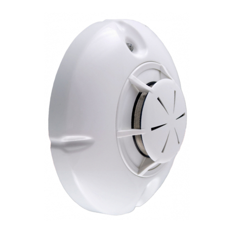
ELOTEC ASPECT 2010 Series User manual

ASPECT
Aspirating Smoke Detector,
NITRO and GRIZZLE;
Conventional, Addressable and Stand-alone
INSTALLATION MANUAL
IMA 201 006 R2D
ENGLISH

IMA 201 006 R2D Installation Manual ASPECT 2010
2
TABLE OF CONTENTS
TABLE OF CONTENTS ....................................................................................................................................2
1. INTRODUCTION............................................................................................................................................4
1.1. The ASPECT 2010 series ....................................................................................................................... 4
1.2. Applications ............................................................................................................................................. 5
1.3. Environmental adaptation and sensitivity ................................................................................................ 6
1.4. Installation instructions ............................................................................................................................ 7
1.5. Aspect Tool.............................................................................................................................................. 8
1.5.1. Installation......................................................................................................................................... 8
1.5.2. Get started ........................................................................................................................................ 8
1.5.3. Connect to Aspect............................................................................................................................. 9
1.5.4. Connecting to a new Aspect for the first time ................................................................................. 10
1.5.6. Overview ......................................................................................................................................... 11
2. OPERATION................................................................................................................................................13
2.1 Indications............................................................................................................................................... 13
2.2 Buttons.................................................................................................................................................... 13
2.3 Status read-outs ..................................................................................................................................... 14
2.3.1. Event logs ....................................................................................................................................... 14
2.3.2. System and real-time information ................................................................................................... 15
2.3.2.2. ASPECT tab – generic device information............................................................................... 15
2.3.2.1. FLOW tab – air flow and calibrated thresholds ........................................................................ 15
2.3.3. Program parameters ....................................................................................................................... 16
3. PROCEDURES FOR ALARMS AND FAULTS...........................................................................................17
3.1. Fire alarm............................................................................................................................................... 17
3.2. Service alert........................................................................................................................................... 17
4. PIPELINE PARTS AND ACCESSORIES ...................................................................................................18
4.1. Sampling pipes ...................................................................................................................................... 18
4.1.1. General ........................................................................................................................................... 18
4.1.2. Parts overview ................................................................................................................................ 19
4.2. AU 002 air exhaust kit ........................................................................................................................... 20
4.2.1. Purpose of the exhaust kit .............................................................................................................. 20
4.2.2. Installing or removing the exhaust kit ............................................................................................. 20
4.3. Sniffer * .................................................................................................................................................. 21
4.3.1. Purpose of the sniffer...................................................................................................................... 21
4.3.2. Installing a sniffer with sleeve ......................................................................................................... 21
4.4. VULCAN dust- and condensation filter.................................................................................................. 21
4.4.1. Purpose of the filter......................................................................................................................... 22
4.4.2. Installing the filter ............................................................................................................................ 22
5. PLANNING...................................................................................................................................................23
5.1. Cable ..................................................................................................................................................... 23
5.2. Pipelines ................................................................................................................................................ 23
5.2.1. Pipe length ...................................................................................................................................... 23
5.2.2. ASPECT placement and pipe path ................................................................................................. 23
5.2.3. Sampling points .............................................................................................................................. 23
5.3. Special applications............................................................................................................................... 24
5.3.1. Greenhouses .................................................................................................................................. 24
5.3.2. Poultry and pig farms ...................................................................................................................... 24
5.3.3. Churches......................................................................................................................................... 25
5.3.4. Deep freeze storage ....................................................................................................................... 25
6. INSTALLATION...........................................................................................................................................26
6.1. Pipes...................................................................................................................................................... 26
6.1.1. Preparations.................................................................................................................................... 26
6.1.2. Installation....................................................................................................................................... 26
6.1.3. Sampling points .............................................................................................................................. 27
6.1.4. Marking sampling points ................................................................................................................. 27
6.1.5. Pipe entry into ASPECT.................................................................................................................. 28
6.2. Aspect.................................................................................................................................................... 29

IMA 201 006 R2D Installation Manual ASPECT 2010
3
6.2.1. Opening the ASPECT ..................................................................................................................... 29
6.2.2. Cable entry...................................................................................................................................... 30
6.2.3. Loop connection.............................................................................................................................. 30
6.2.4. Wireless systems ............................................................................................................................ 30
6.2.5. Mains connection ............................................................................................................................ 30
6.2.6. Battery connection .......................................................................................................................... 31
6.2.7 External power supply (optional) ..................................................................................................... 31
7. COMMISSIONING .......................................................................................................................................32
7.1. Calibration.............................................................................................................................................. 32
7.2. Important check points .......................................................................................................................... 33
7.3. Verification and documentation ............................................................................................................. 33
7.3.1. EloVac............................................................................................................................................. 33
7.3.2. System report in Aspect Tool.......................................................................................................... 33
8. PROGRAMMING.........................................................................................................................................34
8.1. Air flow and disablement ....................................................................................................................... 34
8.2. Power, signaling and sensitivity............................................................................................................. 34
8.3. Sensitivity, day/night modes .................................................................................................................. 35
9. MAINTENANCE...........................................................................................................................................36
9.1. Suggested service intervals................................................................................................................... 36
9.2. Annual inspection .................................................................................................................................. 36
9.3. Testing the Aspect................................................................................................................................. 37
9.3.1 Test Mode (Stand-alone only) ......................................................................................................... 37
9.4. Replacing the main filters ...................................................................................................................... 38
9.5. Inspection and replacement of DIAMANT ............................................................................................. 38
9.6. Cleaning the flow sensor ....................................................................................................................... 39
9.7. Replacing the sensor kit ........................................................................................................................ 39
10. TECHNICAL SPECIFICATIONS...............................................................................................................41
10.1. General ................................................................................................................................................ 41
10.1.1 Mechanical..................................................................................................................................... 41
10.1.2 Electrical......................................................................................................................................... 41
10.1.3 Environment................................................................................................................................... 41
10.1.4 Indications...................................................................................................................................... 41
10.1.5 Buttons ........................................................................................................................................... 41
10.2. EN54.................................................................................................................................................... 41
10.3. Outputs ................................................................................................................................................ 41
10.3.1 Voltage outputs .............................................................................................................................. 41
10.3.2 Relay outputs ................................................................................................................................. 41
10.4. Power supply ....................................................................................................................................... 42
10.4.1 Integrated....................................................................................................................................... 42
10.4.2 External (optional).......................................................................................................................... 42
10.4.3 Battery capacity ............................................................................................................................. 42
11. ADDITIONAL INFORMATION...................................................................................................................43
11.1. Approval / Certificate numbers ............................................................................................................ 43
Appendix A – ASPECT CPU board...............................................................................................................44
Appendix B – Connections for conventional systems...............................................................................45
Appendix C – Connections for addressable systems................................................................................46
Notes for specific systems............................................................................................................................ 46
Appendix D – Connections for stand-alone unit.........................................................................................47
Appendix E – Program functions .................................................................................................................48
Appendix F – Service codes .........................................................................................................................49
Appendix G – CE marking and declarations ...............................................................................................50

IMA 201 006 R2D Installation Manual ASPECT 2010
4
1. INTRODUCTION
1.1. THE ASPECT 2010 SERIES
The ASPECT 2010 series of Aspirating Smoke Detectors are highly sensitive for use in computer rooms and other
clean rooms with high demands for early detection of smoke and fire gases. Recommended for use in churches
and office spaces, using capillary sampling points (sniffers) for unobtrusive installation.
Additionally, ELOTEC ASPECT 2010 is built to handle rough conditions with dust, condensation, and ammonium
gases, making it the natural choice for protecting industrial production areas as well as livestock rooms and
greenhouses.
The ASPECT 2010 can be delivered in a number of variations – as a stand-alone system, or for connection to
conventional or addressable fire alarm panels, wired as well as wireless. Several sensor options are also
available.
Each version uses a specially adapted CPU board and firmware for optimal function.
The stand-alone ASPECT is approved as a control panel, and can be supplied with a number of integrated
modules that provide extra functionality.
•GSM transmitter for alarm transmission with voice messages or text (SMS) *
•Network module for remote control or connection to building management systems *
•Control module for approved wireless smoke detectors/alarms and alarm device in the 868 MHz band. *
The ASPECT is manufactured in an anodized aluminum alloy specially developed to maintain its good look even
after extended use in all environments. The top and bottom parts are made of PC/ABS. The closed housing with
overpressure ensures that dust and moisture do not reach the electronics.
The aspirating fan and housing are designed to balance effect and noise, which makes the ASPECT one of the
most silent aspirating smoke detectors available.
•Human speech produces approximately 60 dB, an ASPECT with standard settings produces 55 dB.
•The noise level can be lowered further (5-10 dB) by installing the exhaust kit AU 002.
•Special soundproofing with the fan in “silent mode” can be delivered, lowering the emitted noise all the
way down to 35 dB – the pipeline will naturally have to be shortened correspondingly (see separate pipe
design for dwellings).
A PSU is integrated, but the ASPECT can also communicate with an external 12V or 24 V power supply in cases
where extra capacity is required. (The internal battery must then be removed.)
The ASPECT is also prepared for accepting signals from external filters on the pipeline.
ASPECT has several levels of internal tests:
•Airflow is constantly monitored in order to reveal problems with filters or pipelines.
•Every month, an automatic verification of the flow sensor is performed to ensure that the constant filter
monitor isn’t degraded. By performing this test, the ASPECT achieves a complete test of its internal
processes.
•Sensors run continuous self-diagnosis, and possess an intelligent test system that provides notification
when the sensor needs to be cleaned (CleanMe).
Simple installation and service:
•External flanges ensure that the unit can be installed without touching its internal components, and helps
maintain the integrity of the protective housing.
•The top lid has been designed to allow easy access to the connection terminals in the upper part of the
unit, and can be opened using special tools concealed behind the bottom lid.
•ASPECT allows the door to be opened for inspection and filter replacement for 4.5 minutes with no need
to operate the control panel.
•No manual calibration is required, neither for sensitivity nor filter monitoring. This means the sensitivity
can never be adjusted outside the approved range.
“PipeDraw” planning software provides assurance that EN 54 is followed, and is very easy and efficient in use.
Required components are listed and priced automatically, both for ordering from Elotec and for the offer to the
customer.
*) Not tested by VdS

IMA 201 006 R2D Installation Manual ASPECT 2010
5
1.2.
A
PPLICATIONS
The ASPECT can be supplied with different types of sensors, and is very well suited for many different areas.
Some examples are shown below.
Churches Computer / switch rooms and technical installations
Heavy industry and warehouses
Sports- and swimming halls Office environments
Agriculture and greenhouses

IMA 201 006 R2D Installation Manual ASPECT 2010
6
1.3.
E
NVIRONMENTAL ADAPTATION AND SENSITIVITY
When planning an aspirating smoke detector installation, the desired sensitivity class (A/B/C) according to EN
54-20 must be determined. This could be specified by the customer, consultants, authorities, or through
regulations. PipeDraw will indicate if the planned pipeline achieves the required class with the chosen sensor, or if
a different variant must be used.
If smoke or gases are naturally occurring in the secured area, there are several possibilities for adaptation in order
to avoid nuisance alarms.
1. Order Aspect with sensors fit for the environment – three different sensitivity levels per sensor type.
a. Sensor kit can be easily replaced on-site if the wrong choice was made, or the operating
conditions change at a later time.
2. Use the app ASPECT TOOL to set reduced sensitivity for the affected area.
•Medium is used where no special conditions indicate otherwise.
•High may be used to maintain the desired class with long pipelines and many sampling points, primarily in
clean environments where a regular smoke detector can survive.
•Normal is used where other variants are expected to be too sensitive, typically in environments with
extreme amounts of dust or air pollution, as well as certain special applications, like freeze storage.
Remember that by using the companion app, Aspect can be programmed, if the customer wants, to have
higher sensitivity at night than during work hours. See 8.3. Sensitivity, day/night modes, page 35.
Ordering information:
Select one element from each column to find the ordering code for the desired version of Aspect or Sensor Kit.
NB! If ‘Sensitivity’ is not specified, Aspect / Sensor Kit will be delivered with Medium sensitivity.
Base Sensor Sensitivity - System (AE2010 only)
AE2010
SENSORKIT N= Nitro
G= Grizzle
N= normal
(none) = medium
H= high
-
V= Voice
M= Magnum
R= Royal
S= Stand-alone
Example: AE2010NN-V
SENSORKIT-G
(Aspect Nitro Normal for Voice)
(Sensor kit Grizzle Medium)

IMA 201 006 R2D Installation Manual ASPECT 2010
7
1.4.
I
NSTALLATION INSTRUCTIONS
Please read this manual carefully before beginning the installation.
Throughout the manual, there will be paragraphs marked . These are to be considered recommendations or
advice to make the installation easier.
Other paragraphs are marked . These instructions must be followed to ensure that the system will function as
intended.
The symbol may be used to indicate other interesting facts.
In several places in this manual you will find so-called QR codes.
These can be scanned with your smartphone to show items such as
YouTube videos, web pages or apps. If you don’t already have a
barcode scanner installed on your phone, try “QR Droid” for Android
devices, or “QR Reader for iPhone”.
Study the plans made by the project planner, and follow them carefully. The
authorized planner must approve any divergence from the plan. Use cable and
pipe types as prescribed by Elotec. Pipes, bends and fixing sleeves must be
delivered by ELOTEC for the system to be approved. ELOTEC can also supply
a selection of signal cable for wired systems. Other installation materials should
be provided by the electrical contractor.
The connection of mains voltage to the unit must be performed by an authorized electrical contractor, and in
accordance with existing regulations.
Always remember that program settings like the flow window must be adapted to the building mass and
application. See page 48. If unexplained flow faults occur repeatedly, this indicates that the normal air
pressure fluctuates too much to maintain the chosen level of P1 (1-10) and/or time of P6 (1-3).

IMA 201 006 R2D Installation Manual ASPECT 2010
8
1.5.
A
SPECT
T
OOL
For simple commissioning, configuration and service, the app Aspect Tool is used. It is available for
Android smartphones and tablets, and communicates with the built-in WiFi diagnostics module.
1.5.1. Installation
Search for Elotec in the Google Play store, or scan the QR code above. Select the
Aspect Tool app, and press “Install”. Accept the permissions requested by the app.
Access to identity and contacts is only used to retrieve the e-mail address for your
Google account, as this is used for licensing.
It is recommended to activate automatic updates to ensure that you always
use the most recent version.
1.5.2. Get started
When you start Aspect Tool for the first time and touch one of the icons, you will be asked to fill in some user
information.
NB! No operations are available until you have filled in your name, company and e-mail address.
The “Handshake” button is your starting point. White cuffs indicate that connection
has not been established. The first time you touch this, you will be asked if you want to
run in demo mode or buy an access key.
In order to connect to a physical Aspect device, you need a key. Press the button “Buy key” to unlock the
app. A licence key can be ordered from Elotec. Remember to supply the e-mail address shown in the
field “Account ID” under user information. The key is valid for one year from the date of purchase.
NB! Remember to retain your order confirmation or write down the code in case you switch phones during the
lifetime of the key.

IMA 201 006 R2D Installation Manual ASPECT 2010
9
1.5.3. Connect to Aspect
Press the “handshake” button to connect to Aspect. If you are not
connected to the correct network, you will see the message on the
right.
Press “Open Wi-Fi settings” and connect to the wireless network
“Aspect_WiFi”. Then, press the back-button of your device to
return to Aspect Tool.
If the network “Aspect_WiFi” is not displayed, activate the Wi-Fi
module in the Aspect by opening the door and pressing the green
button in front. The blue LED should light up.
When connection with Aspect has been established, the cuffs on the “handshake”
button will turn green. Additionally, the wireless symbol in the top bar will change from
red to green – this symbol is visible in all screens.

IMA 201 006 R2D Installation Manual ASPECT 2010
10
1.5.4. Connecting to a new Aspect for the first time
When the app connects to an Aspect device it doesn’t already
know about, you will be asked to register system data.
On later connections to the same Aspect, data for this device will
be loaded automatically.
Register the date of installation. The current date is automatically
suggested.
Set a date for the next battery replacement. Elotec recommends
that standard lead-acid batteries are replaced every three years.
Register the name of the customer.
Type a name for the project or installation. Use a description that
will allow you to recognize the installation later.
If you input a known customer in the previous stage, existing
projects registered on the same customer will be suggested.
State who is responsible for the project. This could be your group
leader, or an external consultant. Copy of system documentation
will be sent to the e-mail address given here.
State where the system is installed. Postal code must be
provided, street address is optional.
Describe the location of the Aspect within the installation, so that
you can easily find it again later.

IMA 201 006 R2D Installation Manual ASPECT 2010
11
1.5.6. Overview
The following screen is displayed when you start the app. Here, you will find icons to access the different
functions. The app has been divided into two zones – a “green zone” for safe readout of information, and a “red
zone” for making changes to the Aspect. Also on the start screen, there is a separate button for initiating a
connection with an Aspect, and a shortcut to the calibration screen for ease of access during commissioning.
Status readouts, green zone
The green zone represents safe functions for readout. It is not possible to make changes to the configuration
through these functions.
•Event logs
•Program parameters
(air flow/disablement)
•Status information
•Program parameters
(power/signaling)
Status readouts, green zone
Handshake / connection
Edit user information
Shortcut to calibration
Help
Configure Aspect, red zone

IMA 201 006 R2D Installation Manual ASPECT 2010
12
Configuration, red zone
The red zone represents functions that will affect the operation of the Aspect.
•Configuration (air
flow/disablement)
•Day/night mode
•Configuration
(power/signaling)
•Clear event log
•Calibration
•Load presets etc.
User information
Under user information, you provide contact information that is used for filling in and sending system reports. The
account ID is automatically retrieved from your phone (Android only), and is used for licensing. The fields Name,
Company, and My e-mail must be filled in before you can start using the app. Touch the diskette symbol to save
changes.

IMA 201 006 R2D Installation Manual ASPECT 2010
13
2. OPERATION
2.1
I
NDICATIONS
Green Power LEDs on: ..........................Normal operation
Green Power LEDs off: ..........................Mains power is missing
Green Power LEDs flashing:..................Abnormal condition, battery or charger (specified in event log)
Service LED flashing:.............................Aspect not calibrated
Red area LED on:...................................Smoke detected in corresponding area
Yellow area LED flashing: ......................Area disabled
Yellow area LED on: ..............................CleanMe
Service LED on: .....................................Generic service message (specified in event log)
Sounder LED on:....................................Service required on sounder output – open circuit or missing EOL
Sounder LED flashing: ...........................Test mode
2.2
B
UTTONS
Two buttons – red and green – have different functions depending on product version.
NB! Make sure the text inserts are installed correctly.
Stand-alone Aspect:
Red button: Deactivate the integrated sounder output.
Green button: Reset the Aspect.
NB! Silencing the attached sounders with the red button will activate the fault output. This is logged as proof of
intentional user operation.
Addressable / conventional:
Red button: Disable Aspect (both areas).
Green button: Re-enable Aspect (only for local disablement with powered loop).
Buttons may also be used to configure the Aspect directly at the device if you cannot connect using Aspect Tool
on your smartphone or tablet. See Appendix E – Program functions, page 48.
FIRE
Silence/
disable
Service/
disabled
SERVICE
FIRE
Reset
/
enable
Service
/
disabled
Sounde
r

IMA 201 006 R2D Installation Manual ASPECT 2010
14
2.3
S
TATUS READ
-
OUTS
This section describes how to read information from the Aspect by using the Aspect Tool app for smartphones.
These are safe operations that are carried out in the green zone of the app – no settings can be changed here.
The descriptions assume that you are already connected to the Aspect as described in section 1.5.3, page 9.
2.3.1. Event logs
In Aspect Tool: Description of and recommended action for the last event is displayed.
This screen has three tabs, letting you switch between showing the latest service message, latest alarm and latest
configuration change.
•The Detail button will display detailed information on system values at the time of the event.
•The More button leads to a combined list of all logged events.
•The envelope icon at the top lets you send the event log to a given e-mail address.
oPlease note that the e-mail will not be sent immediately – you have to disconnect from the Aspect
and connect to a mobile or wireless network with an Internet connection first.

IMA 201 006 R2D Installation Manual ASPECT 2010
15
2.3.2. System and real-time information
In Aspect Tool: Status information divided onto several tabs.
2.3.2.2. ASPECT tab – generic device information
This tab displays an overview of useful information such as serial number, product variant and key dates.
System type: Aspect employs customized firmware based on the type of system it is meant to connect to.
•Conventional
•Addressable
•Stand-alone
2.3.2.1. FLOW tab – air flow and calibrated thresholds
It is recommended to write down these values. Check that the actual air flow is not too close to the thresholds for
no reason.
The Aspect door shall be closed during readout of flow values.
The value AVERAGE is the mean flow value over the last 3 hours, and this is the value you should relate to in
order to determine if conditions are OK / Aspect is correctly calibrated
The value NOW is the real-time flow integrated over 10 seconds, and will let you see continuous variations.

IMA 201 006 R2D Installation Manual ASPECT 2010
16
2.3.3. Program parameters
It is easy to verify the value of program parameters with no risk of changing anything. Parameters have been
divided into two groups as shown below. For an overview of possible values, see Appendix E – Program functions,
page 48.
In Aspect Tool: Parameters related to air flow and disablements.
In Aspect Tool: Parameters related to power, signaling and sensitivity.

IMA 201 006 R2D Installation Manual ASPECT 2010
17
3. PROCEDURES FOR ALARMS AND FAULTS
3.1.
F
IRE ALARM
The alarm location is specified through zone indication or device text on the connected fire alarm panel (if any).
A red LED on the ASPECT front indicates the area where smoke has been detected.
Check all rooms that are covered by the indicated pipe area. If no visible smoke can be observed, it is necessary
to inspect the area carefully.
A smoldering fire may not be visible until it bursts into flames at a much later time.
Operation varies, depending on whether the Aspect is connected to a fire alarm panel or not.
Aspect connected to a fire alarm panel:
Alarms are silenced and reset at the control panel – no operation is required at the Aspect
Stand-alone Aspect:
Red button: Deactivate the integrated sounder output.
Green button: Reset the Aspect.
NB! Silencing the attached sounders with the red button will activate the fault output. This is logged as proof of
intentional user operation.
3.2.
S
ERVICE ALERT
Conditions that require action by the end user or installer are indicated by the generic service LED on the ASPECT
front. To determine the nature of the condition, check the event log.
The purpose of service messages is to make the user aware of internal or external conditions that may affect the
functionality of the aspirating smoke detector system if the condition persists. It is important that the cause is
identified, and any non-conformities are corrected. Please note that certain service messages are normal after
events such as power outages, but may indicate a problem if the message persists after the situation has returned
to normal.
Events are easily displayed in Aspect Tool, but could also be indicated by blinking patterns on the device.
In Aspect Tool: Recommended action for the latest event is displayed.
Operation varies, depending on whether the Aspect is connected to a fire alarm panel or not.
Aspect connected to a fire alarm panel:
Service alerts are silenced and reset at the control panel – no operation is required at the Aspect.
Please note that if the cause of the alert has not been corrected at the device, the alert will return. If an Aspect
loses all power and shuts down, a fault will be displayed at the control panel.
Stand-alone Aspect:
Red button: Deactivate the integrated buzzer.
Green button: Reset the Aspect.
Please note that the fault relay is fail-to-safe, and will trigger if Aspect loses all power.
The event log can be cleared by shorting S100 (Appendix A, item 14 – page 44)
for a moment. This could be done after an annual inspection of the installation.
RESET

IMA 201 006 R2D Installation Manual ASPECT 2010
18
4. PIPELINE PARTS AND ACCESSORIES
4.1.
S
AMPLING PIPES
4.1.1. General
Air samples are transported to the detection chamber in ASPECT through pipes. ASPECT systems use pipes with
an outer diameter of 25 mm and an inner diameter of 22 mm.
Original pipes are marked with the Elotec logo to assure that approved pipes are used. Marks are also
applied at one metre intervals to assist in correct placement of sampling holes, as well as a guide line
along the length of the pipe to help avoid twisting the pipeline.
According to VdS/EN54-20, pipe parts must comply with EN61386-1, at least class 1131. Use only
approved original Elotec pipes that fulfil additional demands to rigidity (prevents drooping) and surface
finish. See “IMA 000 109, Pipe layout design and tables”.
Elotec pipes are delivered in 4 m segments that may be cut to length where needed. To ensure clean cuts with no
burrs, use the ELOCUT cutting tool.
Joins are made through special sleeve couplings or bends – no glue is needed, as the sleeves are conical and
supplied with a sealing agent inside.
The entire pipe system is fixed to walls and ceilings using fastening brackets. The standard clamp CL 250 is open,
and the pipes can be pushed straight in. The clamps are spacious enough to allow free movement of the pipes,
which is important where large temperature variations are to be expected. Wire suspension is also an option.
CL 250 CL 255 CL 250 W CL 251 W
Other parts may be used in certain applications.

IMA 201 006 R2D Installation Manual ASPECT 2010
19
4.1.2. Parts overview
The following are the parts that may make up a pipe system:
4 m lengths of 25 mm pipe:
PL 252 P – grey plastic, standard package of 13 pipes (total 52 m)
PL 252 – grey plastic, single pipe
PL 253 P – red plastic, standard package of 13 pipes (total 52 m)
PL 253 – red plastic, single pipe
AL 250 – aluminium, single pipe
Sleeve couplings:
SK 252 – grey plastic
SK 253 – red plastic
AL 250 S – aluminium
Bends:
BE 252 – 90° grey plastic
BE 252-45A – 45° grey plastic, f/f
BE 252-45B – 45° grey plastic, m/f
BE 253 – 90° red plastic
BE 253-45A – 45° red plastic, f/f
BE 253-45B – 45° red plastic, m/f
AL 250 B – 90° aluminium
Fastening brackets:
CL 250 – simple bracket, grey
CL 250 W – simple bracket for wire suspension, grey
CL 251 W – 'S-hook' bracket for wire suspension, black
CL 255 – closed bracket, roomy, white
End plug:
EP 250
Special purpose parts:
THUB – mounting bracket / pipe splitter / condensation reservoir *
THUB-LK – extended condensation reservoir for use with THUB *
LK 501 – condensation reservoir for use on pipeline
VF 250 com – heavy duty dust and condensation filter
AU 002 – air exhauster kit
GG 256 – 80 cm sampling branch *
GG 006 – 40 cm branch extension *
SN 250 – sampling point – clips directly onto tube *
SN 285 M – flexible sampling tube, plastic head, 75 cm *
SN 253 P – flexible sampling tube, plastic head, 300 cm *
SN 253 S – flexible sampling tube, steel head, 300 cm *
KG 250 – 4-way join, grey (special applications only) *
KG 253 – 4-way join, red (special applications only) *
TG 250 – 3-way join (special applications only) *
PLP 210 007 – 2-1 hub for combining areas into one pipeline *
*) Part has not been tested by VdS, and shall only be used as instructed by Elotec.

IMA 201 006 R2D Installation Manual ASPECT 2010
20
4.2.
AU
002
AIR EXHAUST KIT
4.2.1. Purpose of the exhaust kit
ASPECT can be equipped with an optional air exhaust kit. The AU 002 has three main applications:
1. If ASPECT is mounted in a room with much airborne dust, it is advisable to install the AU 002 with 0,5m lengths
of pipe to lead the exhaust away from the unit. Otherwise, dust may be dragged back into ASPECT because of
turbulence around the exhaust port.
2. If there is a large difference in pressure between the area where air is sampled and the spot where ASPECT is
mounted, the AU 002 must be employed to lead exhaust air back into the protected area in order to negate the
pressure difference. Both areas must draw air from rooms with approximately the same pressure.
3. Sometimes, the ASPECT may be placed in an office, while sampling air from areas with smelly environments.
In this case, the exhaust kit may be used to redirect air to avoid unpleasant smells.
The length of the exhaust pipes must be calculated into the total pipe length. If very long exhaust pipes are
required, it may be necessary to shorten the sampling pipes in order to keep the response time of
ASPECT within the given limits. As a rule of thumb, exhaust pipes shall be no longer than 4m.
The AU 002 can also be fitted to reduce noise from the ASPECT where the sound of the fan is considered
disturbing (like in churches and office environments).
4.2.2. Installing or removing the exhaust kit
The exhaust kit is easily installed without tools. Just set the kit into the slot in the exhaust port as shown in the
picture, and push until it snaps into place.
ASPECT fitted with AU 002 exhaust kit
1. Bottom cover
2. AU 002 exhaust kit
3. “Key” used for release
The AU 002 accommodates two exhaust pipes, and both must be fitted.
If the kit needs to be removed, one of the “keys” located inside the ASPECT bottom cover may be used to release
the snap as shown in the picture. The AU 002 is then easily pulled free.
1
2
3
Table of contents
Other ELOTEC Smoke Alarm manuals
Popular Smoke Alarm manuals by other brands
Honeywell
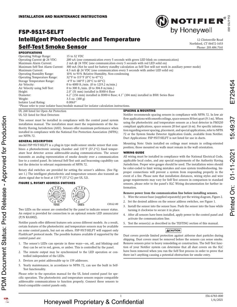
Honeywell NOTIFIER FSP-951T-SELFT Installation and maintenance instructions

Comelit
Comelit 48BFC000 manual

ADEMCO
ADEMCO 5808LST installation instructions
Visonic
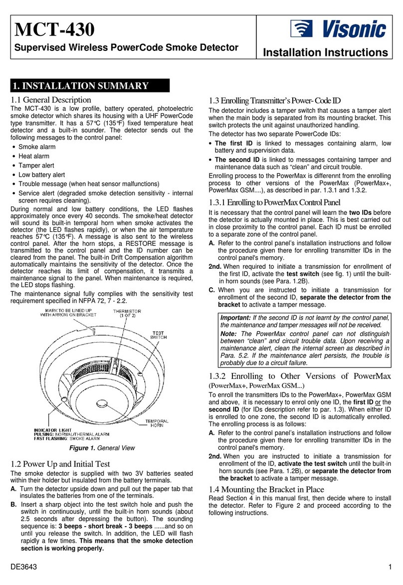
Visonic MCT-430 installation instructions

Bosch
Bosch D285DH installation instructions
Sunmatic
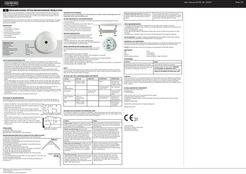
Sunmatic Housegard PEBBLE MINI user manual
