Smartek NUBI 4.0 User manual
NUBI 4.0
Model: NB40LP1
Power supply: Lithium battery 3,6V
PIR: yes
Thank you for pur hasing NUBI 4.0, the intelligent smoke
s reen se urity devi e able to be onne ted to any burglar
alarm system in new or existing systems.
OPERATIONAL OVERVIEW
The devi e is powered by a 3.6V AA size lithium battery
supplied with the produ t, su h as SAFT LS14500 or
similar. This battery provides the ne essary energy to the
devi e for a period of 10 years. The ignition of the smoke
artridge is ensured even when the battery is very low
(2.2V)
NUBI 4.0 effi iently prote ts volumes up to 100 m3. The
smoke generated by NUBI 4.0 is based on in ense and
does not produ e toxi atmosphere as tested a ording to
the TLV-STEL dire tive EU 2017/164 and ACGIH. After use
the room must be ventilated before staying there.
NUBI 4.0 is a tivated through 3 inputs: one input drives the
immediate emission of smoke, while the other two inputs
realize a triple- onsent logi to avoid false alarms. In this
ase, to trigger the emission of smoke, it is ne essary that
the state of the burglar system is armed, then within a time
window of 5 minutes two other onditions o ur:
1) The burglar system goes into alarm
2) The integrated NUBI 4.0 PIR sensor dete ts movement
At the moment the se ond ondition has been rea h, the
smoke will be emitted immediately.
The inputs polarity and logi level an be easily onfigured
using the DIP swit hes in order to interfa e NUBI 4.0 with
any burglar panel.
NUBI 4.0 has got two outputs to inform other devi es
about alarm state and the battery low. The output logi
level an be reversed using DIP swit hes.
The box opening is dete ted with a tamper swit h, its lean
onta t an be onne ted to the burglar panel.
An optional internal siren an be housed inside the box
and plugged to the proper motherboard onne tor. In this
ase the devi e must be powered by an auxiliary battery
pa k, housed inside the NUBI box and plugged into the
appropriate onne tor.
The smoke artridge works only on e, the smoke
emission, when triggered, an no longer be interrupted.
The smoke artridge repla ement is very easy, ea h spare
artridge is provided with a spe ial board soldered on its
wires to be easily plugged on the proper motherboard
onne tor.
INSTALLATION
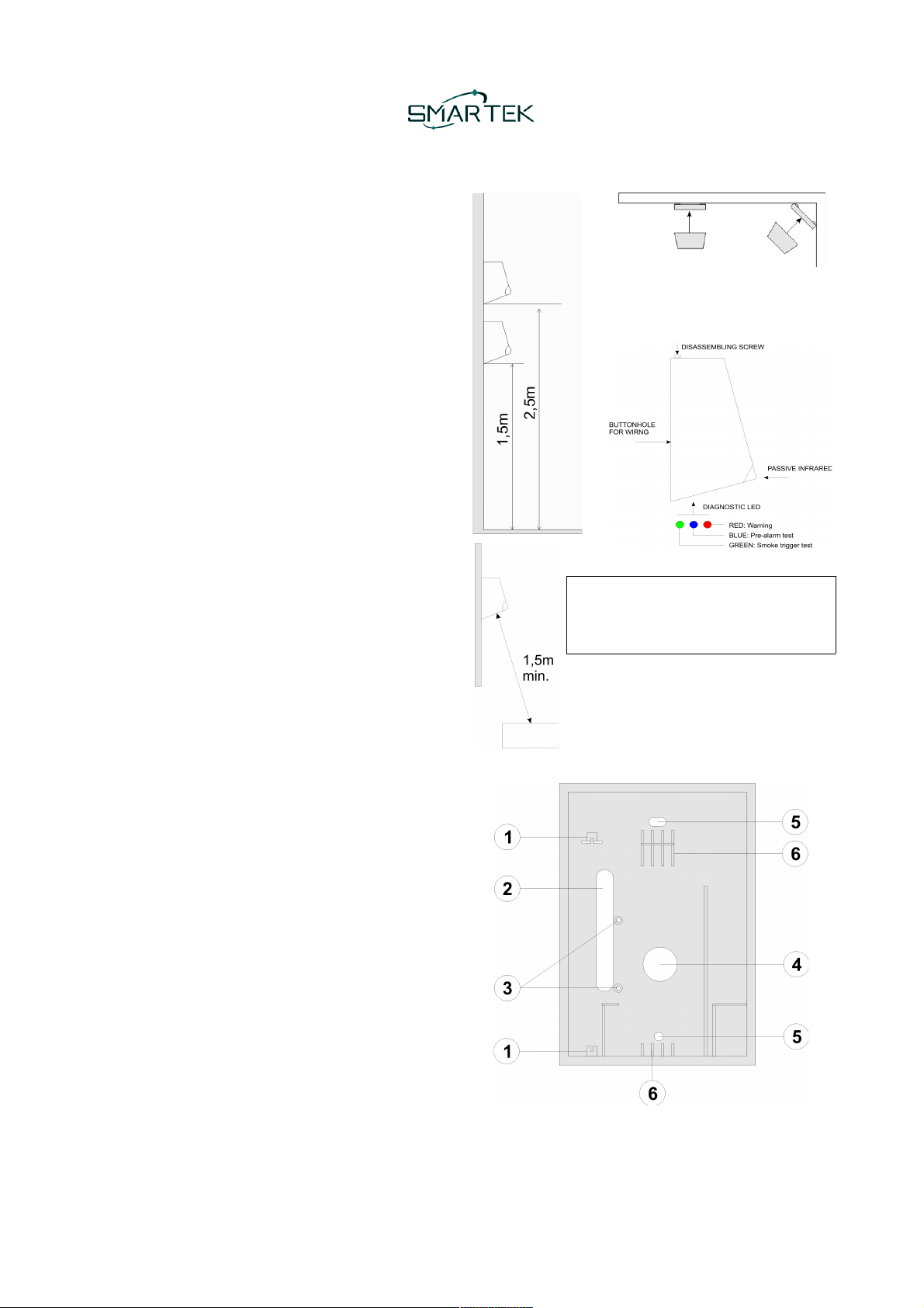
NUBI 4.0 an be easily installed on the
wall or even in a orner at a height
between 150 and 250 m.
WARNING
Do not insert any obsta le at a distan e
of less than 1.5 meters from the smoke
outlet hole.
The best performan e is a hieved when
the jet of smoke oming out from NUBI 4.0
dire tly hits the floor, in this way the smoke
will ool and spread better.
After opening the top over, remove the motherboard to fix
the lower part of the box on the wall.
1 Motherboard rails
2 Cabling wire buttonhole
3 Internal siren fixing spa ers
4 Internal siren sound outlet hole
5 Devi e fixing holes
6 Smoke artridge supports
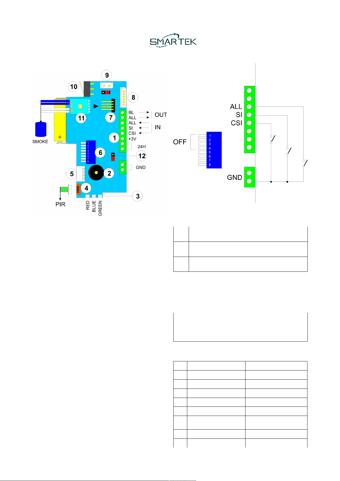
MAINBOARD
1) Main onne tor
2) Buzzer
3) Diagnosti LEDs
4) PIR onne tor
5) Optional auxiliary battery pa k
6) DIP Swit h
7) Smoke artridge onne tor
8) Expansion bus onne tor
9) Internal siren onne tor
10) Tamper swit h
11) Validation board provided with smoke artridge
12) Close this Jumper when the motherboard is
powered with external battery.
MAIN CONNECTOR
GND: Ground power supply
24H Tamper lear onta t
+3V External power supply, input or output.
CSI Immediate smoke delivery (INPUT)
SI System state (armed/disarmed) (INPUT)
ALL Alarm (INPUT)
ALL Alarm (OUTPUT)
BL Battery low (OUTPUT)
+3V EXTERNAL POWER SUPPLY
This terminal takes the battery voltage of NUBI to power
an external devi e or power the NUBI motherboard with an
external battery instead of the one supplied. In the first
ase the Jumper (12) must be open and the battery life of
NUBI will be redu ed due to the onsumption of the
external devi e. In the se ond ase the jumper must be
losed and the supply voltage must not ex eed 3.6V.
INPUTS INTERFACE
When the DIP Swit hes 1..4 are set to OFF, NUBI inputs
will be ome a tive when swit hed to GND, as shown in the
following table:
CSI Trigger the smoke delivery when the input is
losed to GND
SI Burglar system armed when the input is losed to
GND, disarmed when opened.
ALL Burglar alarm a tive when the input is losed to
GND.
With the DIP SW1 the inputs referen e an be hanged
from GND to VCC (3,6V). Using SW2, SW3, SW4 ea h
input logi an be swit hed from normally open to normally
losed as shown the following DIP Swit hes fun tional
table.
In the event that the inputs are not driven with a lean
onta t to GND, neve apply a voltage highe than
3.6V to the input whi h would irreversibly damage the
ele troni ir uit.
DIP SWITCHES
DIP OFF ON
1Input driven to GND Input driven to +3,6V
2CSI input normally open CSI input normally losed
3SI input normally open SI input normally losed
4ALL input normally open ALL input normally losed
5BL output a tive low BL output a tive open
6ALL output a tive low ALL output a tive open.
(Not for internal siren use)
7Operating mode Test mode
8Tamper enabled Tamper disabled
DIAGNOSTIC LEDs
BLUE NUBI pre-alarm in test mode.
GREEN Flash when the smoke artridge is triggered.
RED Warnings.
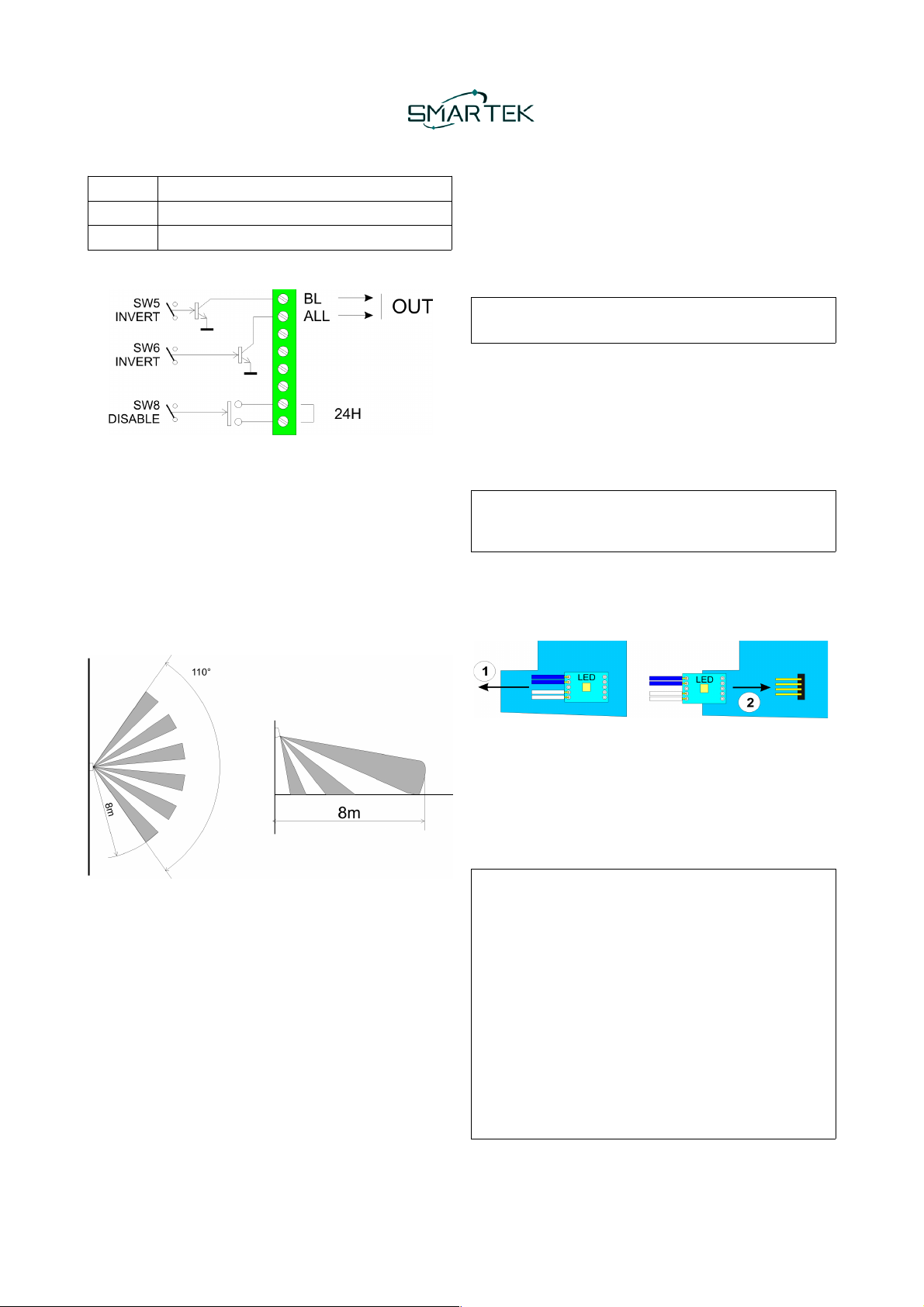
OUTPUTS
ALL output is a tive for 90 se onds starting from the
starting of smoke delivery. SW6 sets the output logi , when
use internal siren, set SW6 to OFF.
BL output is a tive when the battery is low. SW5 sets the
output logi .
24H output is a lear onta t normally losed when the
NUBI 4.0 box is losed, it will open when the box will be
opened. When the SW8 is set to ON, tamper output is
disabled (output is always losed).
PIR RANGE
The pi ture below shows the PIR range
TEST MODE
Set the DIP SW7 to ON to a tivate the test mode. As soon
as the devi e enters test mode, the green LED will flash to
indi ate the battery status:
•3 times: full harge
•2 times: medium harge.
•1 time: quite low.
•RED LED flash + Buzzer: low (to be repla ed)
Then the BLUE led will flash slowly, one time ea h se ond,
to indi ate the test mode is a tivated. In test mode, ea h
time the integrated PIR dete t movement, the RED led
flash and the buzzer will sound for 1 se ond.
the RED led on smoke artridge validation board will be
OFF when the artridge is empty, flash otherwise.
When the SI input dete ts that the system is armed, an
event between the dete tion of the PIR movement or the
a tivation of the ALL input will ause the NUBI 4.0 pre-
alarm state for 15 minutes and the BLUE led will flash
qui kly. When the se ond alarm event o urs within the
pre-alarm period, the GREEN led will flash for 1 se ond to
indi ate the simulation of smoke delivery.
If the pre-alarm was aused by the PIR dete tion, the
alarm onfirmation will be due to the a tivation of the ALL
input. If the pre-alarm was aused by the a tivation of the
ALL input, the onfirmation will o ur whit the PIR
dete tion. In test mode, the smoke artridge will never be
a tivated and never the validation ard will be damaged.
Remembe to activate the ope ating mode (DIP SW7
OFF) at the end of testing.
SMOKE CARTRIDGE REPLACEMENT
When a smoke artridge is empty, it must be repla ed with
a new one. The smoke artridge is supplied with the
validation ard welded to the ends of the wires. Only in test
mode (SW7 ON) the RED led on validation board is OFF
when the artridge is empty, then flash when the artridge
is full.
Remove the NUBI 4.0 batte y powe supply and wait
at least 3 minutes befo e eplacing the smoke
ca t idge.
1) Remove from the motherboard the old validation
ard soldered onto the wires of the empty smoke
artridge.
2) Insert the new validation ard soldered onto the
wires of the new artridge.
Commissioning
We advise to perform a test (see previous hapter Test
mode) before perform a definitive ommissioning of the
devi e.
Set the DIP SW7 to OFF to swit h in operating mode.
We advise to remove the adhesive that prote ts smoke
exit hole of the smoke artridge.
WARNING PROCEDURE TO PREVENT SMOKE
EMISSION AT THE POWER UP
During the first 30 minutes after power the devi e, there
is a spe ial fun tion to prevent unwanted smoke
emissions, for example due to wiring errors.
When the smoke a tivation ondition o urs during this
time, instead of immediately emitting smoke, a warning
pro edure starts and the buzzer emits an intermittent
sound for 120 se onds and the red LED flashes.
It will be possible to stop the a tivation by opening the
box and setting the DIP SW7 to ON or, in ase of
diffi ulty, it will also be possible to unplug the smoke
artridge validation ard from the motherboard.
If this warning pro edure is not interrupted, at the end of
the 120 se onds we will have the emission of smoke.
MAINTENANCE
We re ommend repla ing the smoke apsule every 5
years using only the original repla ement.
WARRANTY
SMARTEK s.r.l. It guarantees its produ ts against all
manufa turing defe ts for a period of 30 months from the
produ tion date shown on the label.
RECOMMENDATIONS
Before leaving, ventilate the rooms thoroughly after the
smoke has been delivered.
TECHNICAL SPECIFICATIONS
Power supply 3,6V lithium battery AA
size su h as SAFT
LS14500 or similar
Minimum operating voltage 2,2V
Battery low output threshold 2,6V
Autonomy About 10 years
Size 9 m x 14 m x 8 m
Saturable volume 100m3
Weight 760g
Smoke average delivery time 25se
Operating temperature From 0°C to +45°C
Storage temperature From -20°C to +55°C
Maximum relative humidity 70%
Inputs SI – System state
ALL – Alarm
CSI – Immediate a tion
Outputs 24H – Tamper
ALL – Alarm
BL – Battery low
ADVANCED WIRING
The inputs interfa e mode an be programmed using the
DIP swit hes SW1, SW2, SW3 and SW4 as previously
explained.
The inputs an be ontrolled not only with lean onta ts
but also with open olle tor or push-pull outputs. The
image below shows a typi al NPN or PNP interfa e.
For any kind of interfa e, the inputs voltage thresholds are
the followed:
Min V Max V
Level 0 GND 0,5V
Level 1 1,9V +Vbatt
12. WORKING DIAGRAM
This manual suits for next models
1
Other Smartek Smoke Alarm manuals


Popular Smoke Alarm manuals by other brands


Wander Oz
Wander Oz LGS Assembly and operation instructions

GEV
GEV Q10 FMR 4467 operating instructions

Panasonic
Panasonic EBL512 Specification sheet

Nexa
Nexa EL1313/KD-101LC user manual

System Sensor
System Sensor 2412 Installation and maintenance instructions

techem
techem smoke detector 2 operating instructions