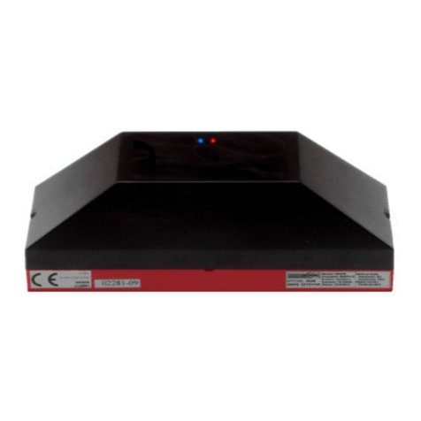
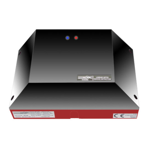
EDS RK100BS-EX User manual

EDS - INFORMAZIONI TECNICHE
1
OPTICAL BEAM SMOKE
DETECTOR
END TO END TYPE
RK100BS-EX
TECHNICAL MANUAL
TECHNICAL INSTRUCTIONS
FOR ASSEMBLY
START AND MAINTENANCE
EDS - V. Ca' Nova Zampieri 6 - 37057 S. G. Lupatoto - VERONA - Tel. 045/ 547529 - Fax 045/8750065 - Email: [email protected] - Web: www.eds.eu
ATEX

EDS - INFORMAZIONI TECNICHE
2
INDEX OF CHAPTERS
1 - reference standards
2 - safety instructions
3 - validity
4 - precautions before installation
5 - authorized personnel
6 - installation
7 - connection cables
8 - electrical connections
9 - operation
10 - optical alignment with BLP100
11 - TX setting
12 - RX setting
13 - self-compensation
14 - exit of Fault
15 - alarm and data memory
16 - total dimming option
17 - activation of the detector
18 - functional verification
19 - indication of the front LEDs
20 - change of sensitivity
21 - maintenance
22 - technical data
QUICK INSTALLATION
The following rules apply to experienced
personnel with previous experience in installing
EDK detectors model RK100BS-EX.
If you do not have this experience, the
operations indicated in the following manual
must be carried out carefully.
1 - Install the RK100BS-EX (TX + RX) detector
on the wall
2 - Connect the cables
3 - Go to the TX and perform the optical
alignment with the BLP-100 Laser pointer
(chap.11)
4 - Set the SW3 selector on the TX in relation to
the TX-RX distance and close the cover
(porthole)
5 - Set the jumpers on the RX JP2-JP3-JP4-JP5-
JP7 (v.cap.12)
6 - Place the JP1 jumper in position 2-3 on the
RX (Alignment ON) to activate the calibration
procedure
7 - Optimize the RX signal using:
• the adjustment screws of the V1-V2-V3
optical crew
• the P1 trimmer for adjusting the signal level
• observing the indication of the blue and red
LEDs (table on page 6) through the porthole
8 - On the RX with trimmer P1, adjust the signal
between 4 and 4.8V. This adjustment is not
critical. It is sufficient that the blue LED is
flashing or on steady. Avoid turning on the red
LED indicating saturation (see chap.12)
9 - Set the sensitivity using the SW2 selector
for the desired sensitivity 40-50-60-70% of
obscuration
10 - Position the jumper JP1 in position 1-2 (OFF
ALI) to end the calibration phase and activate
normal operation
11- Close the RX cover (porthole) within 5
minutes
12 - Wait at least 5 minutes for the detector to
become operational
13 - Perform functional tests by obscuring the
TX or RX
INITIAL SUPPLY CONDITIONS
• SW2 - in position 1 (minimun obscuration
sensitivity )
• SW3 - in position 4 (maximum power
transmitter)
• JP1 - in position 2-3 (optical alignment
inserted)
• JP2-JP3 - in position 2-3 (relay contacts
normally closed NC)
• JP4 - in position 1-2 to have the contact
closed NC because the fault relay is normally
energized
• JP5 - in position 1-2 (memory not inserted)
• JP7 - not inserted (normally de-energized
alarm relay)
• P1 - 1/2 stroke adjustment trimmer

EDS - INFORMAZIONI TECNICHE
3
OPTICAL BEAM SMOKE
DETECTOR
END TO END TYPE
RK100BS-EX
The RK100BS-EX detector is a newly developed optical beam microprocessor-based smoke detector,
composed of a Transmitter (TX) and a Receiver (RX), which bases its operation on the interaction between
the smoke present in a room and a infrared beam emitted by the Transmitter.
Normal installation involves fixing the Transmitter on a wall and on the opposite wall of the room to be
protected, fixing the Receiver.
For a correct installation, we recommend reading and scrupulously following the instructions listed below.
The excellent operating results of the device, will largely compensate for the time taken to read these
instructions.
1 - REFERENCE STANDARDS
EN60079-0 (2012) + A11 (2013)
EN 60079-1 (2014)
EN60079-31 (2014)
EN60529
EN50130-4: 1995 / A2: 2003
ATEX Directive 2014/34 / EU
1.1 - The installation of the RK100BS-EX detector must be carried out according to the rules indicated in
the Italian standards UNI 9795 (Automatic fixed detection, manual signaling and fire alarm systems. Systems
with point detectors of smoke and heat , linear optical smoke detectors and manual signaling points).
We recommend reading the "EDS_Installation Guide " manual available on our website www.eds.eu
In case of installation in countries of the European Community the rules of ‘EN54-14 (Fire detection and
fire alarm systems) must be followed.
In non-European countries the rules of those countries must be respected.
Directive 2014/34 / EU of the European Parliament and of the Council of 26 February 2014.
Certificate: INERIS 13 ATEX 0057X
2 - SAFETY INSTRUCTIONS
2.1 - These instructions are addressed to qualified personnel in accordance with the national laws including
the relative standards and, where applicable, in accordance with EN60079-17 (verification and maintenance
of the electrical systems located in rooms where explosive atmospheres can form and which specifies the
qualification of the personnel assigned to these checks and maintenance.)

EDS - INFORMAZIONI TECNICHE
4
2.2 - The RK100BS-EX detector can be installed in areas with danger of explosion: zone 1 - zone 2 - zone
21 - zone 22.
It must not be installed in a hazardous area classified as zone 0.
2.3 - The technical data indicated on the container must be respected
2.4 - Changes to the product are not permitted
2.5 - The RK100BS-EX detector must be installed only if it is completely intact
2.6 - Only EDS spare parts must be used
2.7 - Ordinary and extraordinary maintenance operations must be carried out only by qualified personnel
with the approval of "expert" personnel
2.8 - The national safety and accident prevention regulations and the instructions indicated with the warning
triangle in this technical manual must be strictly observed.
4 - PRECAUTIONS BEFORE INSTALLATION
4.1 - All installation and maintenance operations must be carried out when an explosive
atmosphere is present
5 - AUTHORIZED STAFF
5.1 - All installation, calibration, start-up, maintenance and operation checks of the RK100BS-EX detector
must be performed only by qualified personnel. These people are qualified by virtue of their experience,
participation in specialization courses, knowledge of the regulations in force, properties and technical
specifications of the product and its use. These people are therefore able to avoid errors or damage and
ensure optimal operation of the product. The installation operations indicated below must be carried out in
a time interval during which there are no hazardous conditions in the environment.
5.2 - The RK100B-EX detector must be used in accordance with the technical data and information in this
manual regarding use, installation and environmental and operating conditions.
66 6 - INSTALLATION
6.1 - For the installation of the RK100BS-EX detector we recommend using the following elements in
addition to the normal instruments (drill, expansion caps, etc.):
• 1 - 7 mm C or star key
• 1 - Tester. We recommend an analog hand pointer.
6.2 - Remove the cover of the TX and RX (porthole).
6.3 - Install the Transmitter at a distance from the ceiling within 10% of the height of the room to be protected
(UNI 9795 standard). This distance can be varied by the designer if there are particular environmental
conditions. Wall mounting must be carried out carefully using the 4 holes provided on the container. If the
wall is in masonry, 4 expansion plugs are enough. It is extremely important that the fixing wall is rigid and not
subject to deformation.
6.4 - Install the Receiver on the opposite wall and at the same height as the Transmitter. It is not necessary that

EDS - INFORMAZIONI TECNICHE
5
the Receiver is positioned perfectly in front of and perpendicular to the reflector (corner errors up to 5 ° in all
directions are allowed). For reasons of cable economy, we recommend installing the Receiver in the position
closest to the control panel.
6.5 - Introduce the cables inside using ATEX certified cable glands
7 - CONNECTION CABLES
7.1 - The reduced current of the device (20 mA with normally not attracted alarm relay and 30 mA with attracted
relay) allows the use of cables with small sections. We recommend, for distances up to 500m, a shielded cable
with 8 wires + screen [2x0.75 mmq (for power supply) + 6x0.22 mmq (for alarm relay contacts)].
In this way it is possible to carry away:
• the alarm signal (terminals C1-N1)
• the pre-alarm / fault signal (terminals C3-N3)
• the analogue signal (signal level) - (terminal 9 - SIGN)
The cable shield must be connected as shown in fig.8.
The box must be connected to the earth.
8 - ELECTRICAL CONNECTIONS
8.1 - To make the connection to the TX and RX terminal board, since the space inside the enclosure is very
small, it is necessary to remove the 4 fixing screws of the electronic board and position it adequately to
make the electrical connections on the terminal board. Then reinstall the card in its initial position.
Connect the appliance cables as shown in the diagrams in fig.6-7-8.
The symbols shown represent the following:
• (V+) (V-) - power terminals 11 - 30 Vdc (TX and RX)
• C1-N1 - normally closed contact of the Alarm relay. The connection is valid when the detector is not in
alarm state and the jumper JP2 is in position 2- 3. If the jumper JP2 is positioned between 1-2 the contact
is normally open. Terminals C1-N1 are without voltage
• C3-N3 - normally closed contact of the Fault / Fault relay. The connection is valid when the detector is not
in a fault state and the jumper JP4 is in position 1- 2. If the jumper JP4 is positioned between 2-3, the
contact is normally open. Terminals C3-N3 are without voltage. The Fault relay is normally energized (for
intrinsic safety)
• SIG - terminal with analogue output 0-5V of the detector. To be used only during calibration.
Figures 6-7-8 show the diagrams of the terminal board and the classical diagram for connection to a
control unit with terminated lines
9 - OPERATION
9.1 - The RK100BS-EX detector is equipped with a smoke detection circuit produced by a fire:
• DARKENING - circuit sensitive to darkening.
This circuit bases its operation on the decrease in the intensity of the infrared beam, along the optical path
between the TX and RX, caused by the smoke

EDS - INFORMAZIONI TECNICHE
6
10 - OPTICAL ALIGNMENT WITH POINTER
LASER BLP-100
10.1 - The BLP pointers are installed on board the EDS optical detectors in order to speed up the optical
alignment operations between TX and RX (for barrier devices) or between the detector and its optical
reflector (for reflection reflectors)
10.2 - The BLP laser pointer is an accessory that makes the installation of EDS detectors very fast. It allows
a fast primary alignment. However, it is always necessary to carry out the electrical alignment (optimal
signal adjustment). After the electrical alignment, the pointing of the Laser may differ slightly from the
initial one.
10.3 - Warnings
10.3.1 - During the operations described below, take extreme care not to deform the small card that supports
the Laser pointer by impact or pressure, on pain of its misalignment with the optics of the detector. The
Laser BLP pointer has been perfectly collimated with its optic on the optical bench during the assembly
of the detector
10.3.2 - Attention! - when the Laser is switched on, it is not absolutely necessary to point the beam at the
eyes or to look directly at the beam, getting on axis with it
10.3.3 - In the case of long distances between TX and RX, it is advisable to carry out aiming in conditions
of reduced environmental illuminance
12 - TX SETTING
11.1 - On the Transmitter (TX) turn the SW3 selector to one of the positions 1-2-3-4 (fig.5) in relation to the
distance between the TX and RX with reference to the following table:
position 1 ....... distance 25 - 50m
position 2 ....... distance 50 - 75m
position 3 ....... distance 75 - 100m
position 4 ....... distance 100 - 120m
11.2 - Power up the TX transmitter (the blue TX LED will emit a pulse every 10 seconds) and turn on the
pointing laser using the switch (see photo)

EDS - INFORMAZIONI TECNICHE
7
11.3 - Use the V1-V2-V3 bolts (fig.5) to orient the lens of the TX transmitter, so that the Laser beam hits the
RX receiver lens on the opposite wall.
When this happens, the lens of the receiver has an intense bright red spot.
In this way the TX is optically aligned with the receiver RX.
11.4 - on the receiver RX orientate the optic using the bolts V1-V2-V3 so that the red light dot on the white
disk behind the lens and representing the focal point of the incident laser beam, falls to the center of the
white disk (small black hole) where the sensor photo-element is present.
After this operation TX and RX are optically aligned
11.5 - On the TX turn off the alignment laser, close the lid and proceed with the next instructions of the
detector as per manual
12 - RX SETTING
12.1 - On the RX the electrical signal calibration operations must be performed according to the sequence
indicated below
12.2 - Setting the jumpers on the RX receiver
JP1 - jumper to activate / deactivate the optical alignment procedure. To activate the optical alignment
procedure, the JP1 jumper must be inserted in position 2-3 (ON). To deactivate the optical alignment pro-
cedure and thus make the detector operational, the JP1 jumper must be disengaged position 1-2 (OFF):
• JP1 position 2-3 ON .... alignment procedure activated
• JP1 position1-2 OFF ... alignment procedure deactivated
JP2 - JP4 jumpers to set the output contact respectively of the Alarm relay and normally closed NC fault or
normally open NA (see fig.1)
The RK100BS-EX detector is supplied with normally closed NC set contacts. For the Alarm relay the indication
of JP2 is valid if JP7 is in the OFF position.
JP5 - jumper to activate the alarm memory function or deactivate this function (to obtain the detector Auto
Reset)
• in position 1-2 memory off. When the alarm status ceases the detector resets itself (Auto Reset)

EDS - INFORMAZIONI TECNICHE
8
• in position 2-3 memory inserted. In the event of an alarm the detector remains in alarm until the voltage is
removed for 5 seconds
JP6 - jumper for microprocessor Reset
JP7 - jumper for setting the Alarm relay operating mode normally energized or de-energized
• JP7 ON - Alarm relay normally energized (in case of alarm it is de-energized). In this case the indication of
the JP2 jumper shown above is the reverse
• JP7 disabled OFF - Alarm relay normally de-energized (in case of alarm it is energized).
In this case the indication of the JP2 jumper indicated above is concordant
12.3 - Move the Initial Set jumper JP1 (fig.9) to the 2-3 ON position (Alignment) to activate the
initial setting phase
12.4 - The blue and red LEDs will begin to flash in a certain sequence to indicate to the operator the signal
level. In order for the receiver to be initially set so as to guarantee regular operation, the signal level must be
adjusted between 4 - 4.8V using the P1 trimmer.
12.5 - Keep in mind that the cover of the receiver (porthole) when installed will cause a decrease in the
signal due to the absorption of the front glass. In order for the receiver to work smoothly, the measured
signal with the lid inserted must be between 4 and 4.8V.
12.6 - To achieve this result it is therefore necessary to momentarily screw the cover and observe through
the porthole, the flashing of the red and blue LEDs positioned in front of the optic. The flashing of these
LEDs gives an indication of the signal level.
12.7 - Observe the status of the blue and red LEDs on the RX.
The signal level indication is as follows:
• 1 flash of the blue LED indicates 1 Volt
• 1 flash of the red LED indicates 0.5 Volt
• if the signal is less than 0.5V the blue and red LEDs are OFF
• if the signal is between 0.5-1 V, the red LED flashes 1, then 2 seconds remain off and then repeats the
sequence
• if the signal is between 1-1.5 V, the blue LED flashes once, then it remains OFF for 2 seconds and then
repeats the sequence
• if the signal is between 1.5-2V the blue LED flashes 1, after the red LED flashes 1, then 2 seconds remain
OFF and then repeats the sequence
• if the signal is between 2-2.5 V the blue LED flashes 2 times, then 2 seconds remain OFF and then
repeats the sequence
• if the signal is between 2.5-3V the blue LED flashes 2 times, after the red LED flashes 1, then 2 seconds
remain OFF and then repeats the sequence and so on up to 4 V
• if the signal exceeds 4 V, the blue LED flashes with increasing frequency as the signal increases up to
4.7V
• when the signal exceeds 4.7V and is between 4.7V - 4.9V, the blue LED lights up steadily. This is the
optimal calibration position

EDS - INFORMAZIONI TECNICHE
9
12.9 - Then act on trimmer P1 until the signal level indicated by the LEDs and displayed through the porthole,
is between 4 - 4.8V (blue LED flashing or fixed). After a few attempts the result is reached.
This is the optimal calibration position.
This procedure is important because it will ensure a perfect functioning of the detector for a long time.
Warning! - if to obtain this signal level it is necessary to adjust the trimmer in an anti-clockwise
direction almost to zero or, if turning the trimmer with small shifts you notice large variations in
the signal level, it means that the signal sent by the transmitter is too powerful.
In this case it is necessary to decrease the power of the TX by acting on the selector SW3 and turning it
towards lower steps (for example if SW3 was set on 3, rotate it on 2 or even on 1). After carrying out this
operation, the adjustment of the P1 trimmer to obtain the 4 - 4.8V becomes simple and not critical.
12.10 - Attention!
If the signal is adjusted beyond 5V, the detector goes into saturation and the blue and red LEDs light up
steadily. Therefore acting on P1, it is necessary to adjust the signal back to 4-4.8V so that the red LED
turns off and only the blue remains lit (avoid saturation).
GNIHSALF-TLOVNOITALER
TLOV hsalF°N
deLeulB
hsalF°N
deLdeR
5,0<FFOFFO
1-5,0FFO1
5,1-11FFO
2-5,111
5,2-22 FFO
3-5,221
5,3-33FFO
4-5
,331
7,4-4+/-elbairaVFFO
59,4-7,4thgilxiFFFO
59,4>
noitarutas thgilxiFthgilxiF
• if the signal exceeds 4.9V, both blue and red LEDs light up steadily. This indicates saturation.
12.8 - The following table summarizes the above data.

EDS - INFORMAZIONI TECNICHE
10
Warning! - the adjustment between 4 - 4.8V is not critical.
The procedure indicated above is the optimal one.
However it is sufficient that the signal is just above 4V and the blue LED is flashing or on steady,
to have a good calibration.
The microprocessor will automatically compensate for the inaccuracies in the calibration.
However, it is necessary to avoid saturation (red LED lit) because, in this condition, the detector
will not work properly.
12.11 - After carrying out these operations, adjust the alarm level of the circuit sensitive to the Darkening by
acting on the SW2 selector, bearing in mind the following:
• position 1 - low sensitivity - alarm level for dimming at 70% .........................1.5V signal level
• position 2 - medium / low sensitivity - alarm level for dimming at 60% ........ 2.0V signal level
• position 3 - medium / high sensitivity - alarm level for dimming at 50% ....... 2.5V signal level
• position 4 - high sensitivity - alarm level for dimming at 40% .........................3.0V signal level
12.12 - Sensitivity must be adjusted according to the environmental situation.
Normally the calibration must be done for medium sensitivity, but in the case of dusty and perturbed
environments, it will be good to use a lower sensitivity.
13 - SELF-COMPENSATION
13.1 - The internal electronics of the detector is equipped with a special signal compensation circuit. If the
detector is installed inside a particularly dusty room, the dust deposited on the front of the TX and RX
causes a decrease in the signal. This problem is automatically eliminated by the self-compensation circuit.
14 - FAULT OUTPUT
14.1 - As already indicated in chapter 4, the contact of the fault and fault relay is available on the RX terminal
board. This relay is normally energized and is de-energized if at least one of the following conditions is met:
• the signal falls below the calibration value by 90% (optical beam completely interrupted by an obstacle)
• the autocompensation circuit has reached the limit (when this occurs it is necessary to carry out maintenance
of the detector)
• circuit operating anomaly (means failure of some component)
15 - ALARM MEMORY AND DATA
15.1 - The RK100BS-EX receiver is equipped with an alarm memory that can be enabled / disabled using
the JP5 jumper (fig.1):
• jumper JP5 in position 1-2 - memory not activated (OFF)
• jumper JP5 in position 2-3 - memory activated (ON)
When the memory is activated, if the detector goes into Alarm, the alarm output relay and the frontal red
LED remain activated until the alarm stops and the voltage is not removed for more than 5 seconds.
When the memory is not activated, if the detector goes into alarm, the alarm output relay and the front LED
turn OFF as soon as the alarm stops.

EDS - INFORMAZIONI TECNICHE
11
15.2 - Memory of configuration and setting data.
In the event of a power failure, the internal memory retains the data. When the power supply returns the
detector, after an initialization time of about 2 minutes, returns to its normal operation
16 - TOTAL DARKER OPTION
It is possible to activate a special function for rapid total dimming (<1 sec, 90%) which activates only the
fault output (30 seconds delay) and not the alarm.
This could be useful to indicate that an obstacle has been accidentally introduced through the path of the
optical beam. This operating mode is active only when the total blackout occurs very quickly (<1 sec).
To activate this function the operator must insert the JP8 jumper (fig. 1).
The test of this function can be done by quickly obscuring (<1 sec) the RX receiver or the TX. After about 30
seconds of total blackout, the fault output must be activated.
The alarm output must not be activated.
17 - DETECTOR ACTIVATION
17.1 - After adjusting the sensitivity, return the Initial Set jumper JP1 to position 1-2 (OFF ALI) to
terminate the optical alignment and calibration phase on the RX.
17.2 - The blue Alignment LED will start to flash in a particular way (2 slow flashes - 1 pause - 2 quick
flashes and then repeat)
17.3 - Install the RX cover.
The closing operation must be carried out within 5 minutes. The signal level will decrease due to the absorption
caused by the cover
17.4 - The internal electronics waits 5 minutes for the cover to be installed and then performs a rapid
procedure (time 1-2 minutes) to restore the RK100BS-EX signal back to 4.7-5V (normal operation level )
17.5 - Once this adjustment phase has ceased, the detector becomes operational. The blue Alignment
LED ceases the particular flashing indicated in chap.10.2 and starts to flash as indicated in 17.6
17.6 - Every 10 seconds the blue LED will emit a light pulse that indicates the normal operation of the
detector. In the event of an alarm, the red front LED lights up and remains on until the alarm status ceases
or, if the memory function is set, until the power is removed for 5 seconds.
18 - OPERATION CHECK
18.1 - The check is carried out by simply obscuring the TX or RX with an opaque screen.
After more than 10 seconds, the RX must energize / de-energize (see fig.1 - jumper JP7) its Alarm relay
and the frontal red alarm LED must light up. After removing the screen, after 1 second, the Alarm relay must
be reset and the blue LED starts to flash again every 10 seconds.
If the memorization function is activated (see chapt. 15), for recovery, it is necessary to switch OFF the RX
for 5 seconds.

EDS - INFORMAZIONI TECNICHE
12
19 - INDICATION OF FRONT LEDS
19.1 - The TX LED flashes every 10 seconds.
The front LEDs of the RX during normal operation of the detector, give the following indications:
• normal operation: the blue LED flashes every 10 seconds
• alarm: the red LED lights up steadily
• compensation limit, interrupted radius, fault: the blue LED flashes every second
20 - CHANGE OF SENSITIVITY
20.1 - after the installation operations and after a certain period of operation, if for some reason you want to
change the sensitivity of the detector, perform the operation as follows:
• remove the RX cover (it is not necessary to remove the power supply to the appliance)
• change the sensitivity using the SW2 selector
• close the lid
21 - MAINTENANCE
21.1 - The appliance requires simple and regular maintenance. It can be programmed or made
automatic on specific signaling by the detector.
During normal operation, due to dirt and dust deposited on the front of the covers, the signal tends to
decrease.
The detector automatically compensates for this decrease.
However, if maintenance is not performed, after a certain time, the detector reaches the compensation
limit and generates a fault signal due to the decrease in the signal beyond the compensation limit.
So it will be time to clean it in order to restore the initial optical conditions
21.2 - The operations to be carried out are the following:
• remove the power supply
• check the internal terminal board by tightening any loose terminals
• check the optical alignment in the case of settlements of the structure on which the device is mounted
using BLP pointing lasers
In this case, therefore repeat the operations indicated in section 8
• clean the front of the TX and RX covers. It is carried out using a cloth dampened with water with some
traces of soap. Chemicals such as alcohol, ammonia and the like must not be used. Cleaning the front
panel is essential for the correct operation of the appliance
• restore power

EDS - INFORMAZIONI TECNICHE
13
22 - TECHNICAL DATA
• Model: RK100BS-EX
• Name: linear optical smoke detector
• Manufacturer: EDS srl - V. Cà Nova Zampieri 6 - 37057 S.G. Lupatoto - Verona
• Rated power supply: 12/24 Vdc.
• Supply limits: 11-30 Vdc
• Protection against polarity inversion
• TX transmitter consumption: 9.5 mA
• RX receiver consumption:
20 mA with detector not in alarm
30 mA with alarm relay energized
40 mA with turbulence relay energized
• Infrared beam with digital coding which makes the detector insensitive to the flashing of forklifts and the
like
• Special circuit that automatically compensates for signal drift due to opacification of the optical parts
due to dust and dirt
• Optical emission peak frequency: 950 nm
• Maximum angular misalignment of the detector: +/- 0.2 °
• Adjustment of the alarm level for dimming with a 4-position selector:
position 1 - 70%
position 2 - 60%
position 3 - 50%
position 4 - 40%
• Sensitivity adjustment for the turbulence circuit: with 4-position selector
• Alarm relay tripping delay: 10 s
• Fault relay tripping delay: 5 s
• Detector reset time with alarm memory off: approximately 5 s
• Detector reset time with alarm memory inserted: approximately 5 s (removing voltage)
• Operating temperature: -10 + 55 ° C
• Red LED indicator light: alarm status
• Blue LED indication: compensation limit, interrupted radius, fault, normal operation
• Alarm output relay: 1A / 24V d.c.
• Turbulence output relay: 1A / 24V d.c.
• Fault / maintenance output relay: 1A / 24V d.c.
• 0-5 V analogue output for signal level measurement
• Optical range:
25m min - 120m max
• Optical pointing laser on TX and RX: BLP100 - Laser class 2
• Max coverage area: 1,600 square meters.
• Dimensions: mm.
• Container: Ex-d execution - ATEX
• Construction in accordance with EN 54-12
• Certification: VDS - G209131 - 0786 CPD 20803
• Certification: ATEX - INERIS 13ATEX0057X IECEx INE13.0076X
• Protection: IP65
• Weight: 12 Kg

EDS - INFORMAZIONI TECNICHE
14
fig.1
7PJ-2PJSREPMUJGNITTES
repmuJnoitisoPtluseR7PJ
2PJ
2-1
MRALA
tcatnocyaler
ON-nepoyllamron FFO
3-2
MRALA
yllamontcatnocyaler
CN-desolc
2-1
M
RALA
yllamontcatnocyaler
CN-desolc NO
3-2
MRALA
tcatnocyaler
ON-nepoyllamron
SREPMUJGNITTES
repmuJnoitisoPtluseR
1PJ
2-1 sierudecorptnemngila
delbasid
3-2 erudecorptnemngila
delbane
3PJ
2-1
E
CNELUBRUT
tcatnocyaler
ONnepoyllamron
3-2
ECNELUBRUT
tcatnocyaler
CNdesolcyllamron
4PJ
2-1
TLUAF
tcatnocyaler
CN
desolcyllamron
3-2
TLUAF
tcatnocyaler
ONnepoyllamron
5PJ
2-1 yromemmrala
FFO
3-2 yromemmrala
NO
6PJ NOteser
FFO
8PJ
NO tluaFnoitarucsbolatot
detavitca-noitpo
FFO tluaFnoitarucsbolatot
detavitcaton-noitpo

EDS - INFORMAZIONI TECNICHE
15
fig.2
optical beam emitted by the TX
fig.3
040
10
50
distanza [m]
8020 60
30
70
diametro del raggio [cm]
100
10 50
20
60
9030
0
40
80
70
disco bianco
white disc
diodo fotoemittente
photoemitting diode
foro
hole
sensore
sensor
fig.1
view of the white disk inside the optic

EDS - INFORMAZIONI TECNICHE
16
fig.4
VIEW OF INTERNAL PARTS OF THE RECEIVER
1
JP1
3
2
4
3
2
1
MEM
JP4
SENS
Laser BLP100
OFF
V1
2
3
1
3
fault
ON
V3
alarm
JP7 JP5
RX
OFF
JP2
relay
ON
JP8
LED di Allarme
JP6
3
SW2
relay
ALI
V2
2
CN4
1
1
P1
2
1
2
2
3
5
6
LED di allineamento
DS1651B
8
1
9
7
3
4

EDS - INFORMAZIONI TECNICHE
17
P1 - trimmer for signal level adjustment. It is normally set at 50-60% which corresponds to a 5V signal at maximum distance
SW2 - trimmer for adjusting the sensitivity of the circuit sensitive to darkening
• low sensitivity - 70% blackout alarm level ......................................... is obtained in position 1
• medium / low sensitivity - 60% blackout alarm level .......................... is obtained in position 2
• medium / high sensitivity - 50% blackout alarm level ..........................is obtained in position 3
• high sensitivity - 40% blackout alarm level ........................................ is obtained in position 4
V1-V2-V3 - screws for adjusting the optical equipment
CN4 - connector to connect the STS-01 instrument (optional)
JP1 - jumper to activate / deactivate the optical alignment procedure. To activate the optical alignment procedure, the JP1
jumper must be inserted (ON). To deactivate the optical alignment procedure and thus make the detector operational, the JP1
jumper must be disarmed (OFF)
• JP1 position 2-3 (ON) ...... alignment procedure activated
• JP1 position 1-2 (OFF) ...... alignment procedure deactivated
J2-JP4 jumpers to set the output contact of the alarm relay and normally closed fault NC or normally open NA respectively.
• position 1-2 - normally open NO contact output
• position 2-3 - normally closed NC output contact
JP4 (relative to the Fault relay) must be in position 1-2 to have the contact closed because the Fault relay is normally
energized. The RK100BS-EX detector is supplied with normally closed NC set contacts.
For the Alarm relay the indication of JP2 is valid if JP7 is in the OFF position.
JP5 - jumper to activate the alarm memory function or deactivate this function (to obtain the detector Auto Reset)
• in position 1-2 memory off. When the alarm status ceases the detector resets itself (Auto Reset)
• in position 2-3 memory inserted. In the event of an alarm the detector remains in alarm until the voltage is removed for 5
seconds
JP6 - Reset microprocessor jumper
JP7 - jumper for setting the operating mode of the Alarm relay normally energized or de-energized
• JP7 ON - alarm relay normally energized (in case of alarm it is de-energized). In this case the indication of the JP2 jumper
shown above is the opposite
• JP7 disabled OFF - alarm relay normally de-energized (in case of alarm it is energized).
In this case the indication of the JP2 jumper indicated above is concordant
JP8 - Fault option for total dimming - JP8 ON = activated
DESCRIPTION OF INTERNAL PARTS RECEIVER

EDS - INFORMAZIONI TECNICHE
18
VIEW OF INTERNAL PARTS OF THE TRANSMITTER
SW3 - selector for adjusting transmitter power (TX) - power increases from 1 to 4. Power is maximum in
position 4 and minimum in position 1.
fig.5
JP6
Laser BLP100
1
2
TX
SW3
V3
1
3
4
2
POWER
LED
V2
DS1653
V1

EDS - INFORMAZIONI TECNICHE
19
fig.6
RECEIVER TERMINAL
BOARD
V+
V- alimentazione 11-30 Vcc
1
2
TRANSMITTER TERMINAL
BOARD
fig.7
SIG
1
9
contatto relè d'ALLARME
segnale analogico 0-5V
N3
4
8
alimentazione 11-30 Vcc
N1
C3
V-
3
7
C1
contatto relè GUASTO
2
V+
DESCRIPTION OF TERMINALS TX AND RX

EDS - INFORMAZIONI TECNICHE
20
Example of connection of the RK100BS-EX receiver with a zone control panel.
In this case the detector occupies an area of the control panel.
The status of the relays indicated correspond to the rest condition of the detector.
The alarm signal is given by the Alarm relay (for activation of the circuit sensitive to Darkening)
The Fault is signaled using the NC contact of the RK100BS-EX Fault relay.
The values of the alarm and line end resistances will be indicated by the control panel manufacturer.
fig.8
CENTRALE DI CONTROLLO
Allarme
2
-
3
connessione zona1
7
resistenza di fine linea
+
8
4
-
resistenza di
1
V-
contatto relè GUASTO
C1
C3
alimentazione 11-30 Vcc
segnale analogico 0-5V
N3
SIG
N1
contatto relè d'ALLARM
E
V+
9
alimentazione
+
schermo
Table of contents
Other EDS Smoke Alarm manuals
Popular Smoke Alarm manuals by other brands

AMC
AMC 800 Series manual

System Sensor
System Sensor 2151TA Installation and maintenance instructions

AngelEye
AngelEye SA700-AE-UK user manual

Unitec
Unitec EIM-217 operating instructions

elsner elektronik
elsner elektronik Salva KNX TH Technical specifications and installation instructions

Honeywell
Honeywell 5800COMBO Quick installation guide