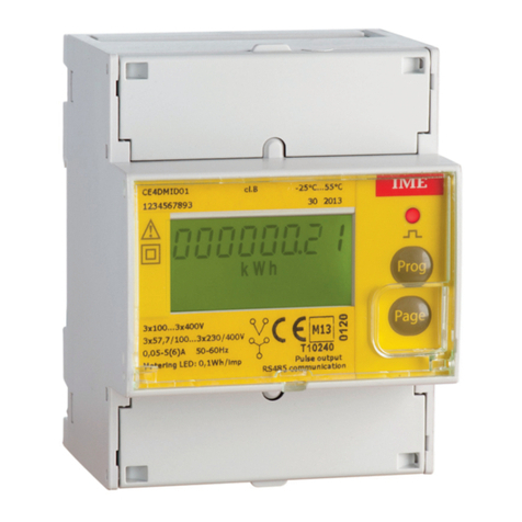
Elotech A4000 Manual

Manual: A4000-XX-X-000-X-X_EN Release: 1.00 ©Elotech GmbH Page 1 36
A4000
Indicator with 4, 8 or 16* zones
* With the extension module R4010 up to 16 zones can be connected.
Depth: 122mm
Format: 96mm x 96mm
DESCRIPTIO A D OPERATI G MA UAL
ELOTECH Industrieelektronik GmbH
Verbindungsstraße 27
D - 40723 HILDEN
FON +49 2103 255 97 0 FAX +49 2103 255 97 29
www.elotech.de Email: [email protected]

Manual: A4000-XX-X-000-X-X_EN Release: 1.00 ©Elotech GmbH Page 2 36
Contents
Contents ........................................................................................................................ 2
1 General Information ................................................................................................. 3
2 Installation Instructions ............................................................................................ 3
3 Type Code ............................................................................................................... 4
4 Connection Diagram ................................................................................................. 5
4.1 Connection Diagram: Power supply, Logic Inputs and Heater Current .................... 5
4.2 Connection Diagram: Monitoring Relay ................................................................ 6
4.3 Connection Diagram: Sensor Inputs .................................................................... 6
4.4 Connection Diagram: Logic Outputs .................................................................... 6
4.5 Connection Diagram: Relay Outputs .................................................................... 7
4.6 Connection diagram Continuous outputs (option) ................................................. 7
4.7 Connection diagram E-Bus for extension module .................................................. 7
4.8 Connection Diagram: Fieldbus Interfaces ............................................................. 8
4.9 Connection Diagram: LAN and USB ..................................................................... 8
5 Display and Keyboard ............................................................................................... 9
5.1 Window-Overview ............................................................................................. 9
5.2 Display screens (Windows) ............................................................................... 10
5.2.1 Window: Actual Process Values .................................................................. 10
5.2.2 Window: Main .......................................................................................... 11
5.2.3 Window: Zone synopsis ............................................................................. 12
5.2.4 Window: Monitoring display ....................................................................... 13
5.3 Adjusting windows .......................................................................................... 14
5.3.1 Window: Entering number value ................................................................ 14
5.3.2 Window: Selection with tiles ...................................................................... 15
5.3.3 Window: Selection List view ....................................................................... 15
5.3.4 Window: Saving to multiple zones .............................................................. 16
5.3.5 Window: Setting text ................................................................................ 16
5.4 More display screens (more Windows) .............................................................. 17
5.4.1 Window: Process ...................................................................................... 17
5.4.2 Window: Graph ........................................................................................ 17
5.4.3 Window: Log (Logbook) ............................................................................ 18
5.4.4 Window: Parameter .................................................................................. 19
5.4.5 Zone – Parameter list ................................................................................ 19
Menu: Limit values ................................................................................ 19
Menu: Sensor settings ........................................................................... 20
Control outputs ..................................................................................... 21
5.4.6 Window: Tools ......................................................................................... 21
Configuration Monitoring 1+2 ................................................................. 22
Configuration Limit 1+2 ......................................................................... 23
Field Bus USB LAN ............................................................................ 24
5.4.7 Wizard ..................................................................................................... 27
5.4.8 Window: System ....................................................................................... 27
Settings ................................................................................................ 28
About Firmware update ................................................................... 29
Configuration Units ................................................................................ 29
Configuration sensors ............................................................................ 30
Configuration Output digital ................................................................... 30
Configuration Output relay ..................................................................... 30
Configuration of continuous outputs (option) ........................................... 31
6 Error Messages ...................................................................................................... 32
7 Technical Data ....................................................................................................... 33

Manual: A4000-XX-X-000-X-X_EN Release: 1.00 ©Elotech GmbH Page 3 36
1General Information
Symbols used:
www.elotech.de
Messages shown by the indicator are written in this font.
MRS / MRE Measuring Range Start Measuring Range End
<§> Symbolizes the factory adjustment of the respective parameters.
2Installation Instructions
Make sure the device is used for the intended purpose only.
A4000 indicators are designed for installation in control panels.
Protect the device against impermissible humidity and contamination.
The permitted ambient temperature range may not be exceeded.
Electrical connections must be made according to valid regulations and by properly qualified
personnel.
If using thermocouple sensors, compensation lines have to be connected directly to the indi-
cator terminals. Sensors may be connected only in compliance with the programmed range.
Sensor cables and signal lines (e.g. logic or linear voltage outputs) must be laid separately
from control lines and mains voltage supply cables (power cables).
In order to maintain CE-Compliance screened detectors - and signal lines have to be used.
It is not permitted to connect the grounds of the sensor-inputs and logic-outputs with each
other.
Separate installation of indicator and inductive loads is recommended.
Interference from contactor coils must be suppressed by connecting adapted RC-combina-
tions parallel to the coils.
Control circuits (e.g. for contactors) should not be connected to the mains power supply ter-
minals of the indicator.
The configuration parameters (Window: System) are generally to be selected first.
Disclaimer of Liability
The contents of this document is checked for the conformity with the hardware and software
described. Nevertheless, we are unable to preclude the possibility of deviations so that we
are unable to assume warranty for full compliance. However, the information given in the
publication is reviewed regularly. Necessary amendments are incorporated in the following
editions.
We would be pleased to receive any improvement proposals which you may have.
The information contained herein is subject to change without notice.
Electronic scrap and
components are sub-
ject to special treat-
ment and must be
disposed of by au-
thorised companies.

Manual: A4000-XX-X-000-X-X_EN Release: 1.00 ©Elotech GmbH Page 4 36
3Type Code
A4000
-
X
-
Z
-
0
-
000
-
DD
-
5
Power Supply
5 24 VDC
Fieldbus Interface
00
No
03
RS 232-C + RS 485 + 0/20mA TTY (incl. E-B s)
09
Profib s-DP (incl. E-B s)
90
E-B s to connect the extension mod le R4010
Zones
1 1 zone
2 2 zones
4 4 zones
6 6 zones
8 8 zones
12 and 16 zones: See note below
Versions
0 O tp t each zone: 1x Logic & 1x Relay (standard)
1 O tp t each zone: 1x Logic & 1x 0-10V o. 0/4-20mA
If 12 or 16 zones are required, an 8-zone indicator and an expansion module R4010 (4 or 8
zones) must be ordered.
The E-bus on the A4000 is required for communication with the R4010.
If the required indicator already has a fieldbus interface, then the E-bus interface is already
available.
If no fieldbus interface is required, key 90 (E-bus) must be selected for the fieldbus.
DD

Manual: A4000-XX-X-000-X-X_EN Release: 1.00 ©Elotech GmbH Page 5 36
4 Connection Diagram
Option continuous
Ground connection
The Ground connection
(flat plug 6,3mm) must be connected to an earth rail via a thick cable (>=4qmm) in the
shortest possible way (<20cm)!
4.1 Connection Diagram:
Power supply, Logic Inputs and Heater Current
Function of the logic inputs:
In_1: no function
In_2: 0 = Parameter “Authorisation” is
adjustable.
1 = Parameter “Authorisation” is not
adjustable.
In_3: no function
In_4: no function

Manual: A4000-XX-X-000-X-X_EN Release: 1.00 ©Elotech GmbH Page 6 36
4.2 Connection Diagram: Monitoring Relay
4.3 Connection Diagram: Sensor Inputs
It is not permitted to connect the grounds of the sensor-inputs and logic-outputs with each
other!
RTD Ni120: The parameter “Sensor Settings Sensor” has to be set accordingly to the con-
nection diagram (2-wire 3-wire)
4.4 Connection Diagram: Logic Outputs
The power supply for the logic outputs has to be wired ex-
ternally:
+24V have to be applied to the terminals B3 and G3.
B3 is connected internally to E3 and G3 is connected to K3.
So the terminals E3 and K3 can be used to loop the +24V.
The 24V are switched to the outputs out x and thus control
the SSRs. Reference potential is the ground of the supply
voltage.

Manual: A4000-XX-X-000-X-X_EN Release: 1.00 ©Elotech GmbH Page 7 36
4.5 Connection Diagram: Relay Outputs
4.6 Connection diagram Continuous outputs (option)
If continuous outputs are existed, the relay outputs are not available.
The GND connection terminals C5 - C7 and H5 - H7 are bridged. The output automatically
switches to current or voltage, depending on the connected load.
4.7 Connection diagram E-Bus for extension module
The extension module R4010, for exptension to 12 or 16 zones, is
connected to the A4000 via the E-bus.
The lines „E-Bus L“ and E-Bus H“ must be connected to the
corrosponding terminals of the R4010.
The connection must be designed as a shielded cable. The shield has
to be conneted the earth (housing) at the R4010 side.

Manual: A4000-XX-X-000-X-X_EN Release: 1.00 ©Elotech GmbH Page 8 36
4.8 Connection Diagram: Fieldbus Interfaces
Type 03 / 07 : Serial Interface / CA
The serial fieldbus module (Type: 03) contains the three interfaces RS232, RS485 und TTY.
By choosing the connection and setting the parameter ”HW-config“ the desired bus is
selected.
Typ 09: Profibus
The 5V-Supply is designed for the
supply of the termination resistors.
Further loads are not allowed.
4.9 Connection Diagram: LA and USB
USB: Save process data, configuration data and alarm data on an USB-Stick.
Write back configuration data from USB-Stick to the indicator.
Make a firmware update. (Please use FAT formatted USB flash drives.)
LAN: Connection to configuration tool EloVision 3.
Read and write parameters by MODBUS-TCP protocol.
Bus Type Remark
A B RS485 03 Parameter HW-config = RS232 RS485
RxD TxD GND RS232 03 Parameter HW-config = RS232 RS485
- + TTY 03 Parameter HW-config = TTY (current loop)
H L CAN 07 Not available at the moment
Pin 3 Data RxD TxD - P
Pin 5 GND
Pin 6 +5V
Pin 8 Data RxD TxD - N

Manual: A4000-XX-X-000-X-X_EN Release: 1.00 ©Elotech GmbH Page 9 36
5Display and Keyboard
The device is equipped with a backlight colour LC-display.
After switching on the indicator and completion of the initialization, the actual process values
of all connected zones are displayed.
The device is operated by menus. The different parameters are displayed mainly in plain text
and can be displayed in various languages.
There are several windows for different functions and settings.
5.1 Window-Overview
Home
Process
Log
Zone
synopsis
Main
Graph
Parameter
Tools
System

Manual: A4000-XX-X-000-X-X_EN Release: 1.00 ©Elotech GmbH Page 10 36
5.2 Display screens (Windows)
5.2.1 Window: Actual Process Values
Display of setpoints and actual process values of all connected zones.
The top right
shows the time.
The hexagon displays the zone number.
If the zone is turned off, the actual process value
displays “OFF“, and the hexagon showing the num-
ber of the zone is grey.
8-zone-indicator:
For every zone the actual process value is displayed.
4-zone- indicator:
For every zone the actual process value is displayed.
16-zone indicator: (in conjunction with 16-zone ex-
pansion module)
The structure is similar to the picture of the 8-zone
indicator.
Below the zones are 2 buttons (+ -) for switching
the zones (1 ... 8) to (9 ... 16) and back.
Zone 4 is set
to the u
nit bar. Monitoring 1 is active.
Contact of Monitoring relay 1 is closed.
Contact of Monitoring relay 2 is open.
Tapping the area of the zone, here zone 2, leads to the main
menu. A grey frame and blue zone symbols show up while
pressing the key.

Manual: A4000-XX-X-000-X-X_EN Release: 1.00 ©Elotech GmbH Page 11 36
5.2.2 Window: Main
This window contains a summary of the other function windows.
One gets to this window by pressing the area of a
selected zone in the window ”Actual Process Value”.
Likewise, you come into this window by pressing the
following icon.
In different windows this symbol appears in the lower
left corner.
Jump to window “Actual Process Value“
Display for all zones: Actual process value, alarms
Jump to window “Zone synopsis“
Display and entry for selected zone: Actual process value, monitoring state
Jump to window “Process“ (List view)
Display for all zones: Actual process value, monitoring state
Jump to window “Graph“
Display for selected zone: Graphical display of the actual value process-
temperature over time
Jump to window “Log“
Display for all zones: Alarm- und status messages
Jump to window “Parameter“
Display and entry for all zones: All zone-parameter
Jump to window “Tools“
Configuration of the monitoring, the alarms and interfaces. (USB, Fieldbus,
LAN)
Calling of the Wizard (set-up assistance)
Jump
to window “
System“
Configuration inputs, outputs, and unit. Setting language, date, sample
time and restart lock-out.
Hold down < 2 sec. = Return to previous window
Hold down > 2 sec. = Jump to window “Actual Process Value“

Manual: A4000-XX-X-000-X-X_EN Release: 1.00 ©Elotech GmbH Page 12 36
5.2.3 Window: Zone synopsis
This window contains the most important information of the selected zone.
In the header the currently selected zone is
shown.
Underneath the actual process value is displayed.
The status of the two monitoring outputs is indi-
cated by the bell symbols.
Display of monitoring 1.
Grey = signal not active. Colored = signal active
Pressing the area leads to the window “Monitoring display”.
The same applies to monitoring 2.
”+“ switchover to the next zone.
Display of the current zone number
” - “ switchover to the previous zone.
Jump to window “Main“
Jump to window “Parameter“
Jump
t
o window
“
Graph“

Manual: A4000-XX-X-000-X-X_EN Release: 1.00 ©Elotech GmbH Page 13 36
5.2.4 Window: Monitoring display
In the header the currently selected zone is
shown.
The key “configuration Moni x Alarm” leads to
the configuration of monitoring and alarms. See
chapter 0
The key “Log” leads to the alarm logbook for fur-
ther information regarding the occurred alarms
The light blue background and the coloured frame shows that the
event “Limit 1 exceeded” has triggered the monitoring. In case the
event needs an acknowledgement, it must be done by pressing the
button.
The dark blue background shows that the event “Sensor error” is
programmed for triggering the monitoring. The event is not active.
The dark grey background shows that the event “System error” is not
programmed for triggering the monitoring.
In case of a system error the monitoring will not be active.
”+“ switchover to the next zone.
Display of the current zone number
” - “ switchover to the previous zone.
Jump to window “Main“
Return to previous window

Manual: A4000-XX-X-000-X-X_EN Release: 1.00 ©Elotech GmbH Page 14 36
5.3 Adjusting windows
5.3.1 Window: Entering number value
This window helps entering number values, here for the setpoint 1.
The header displays the current zone and the
name of the Parameter, here “Setpoint 1 “.
By pressing the number keys the value of the pa-
rameters can be entered. In order to take over
the parameter value, it must be saved by pressing
the “SAVE”– key.
The value
,
entered by pressing the number keys, is now displayed
within the blue frame.
Underneath, on the left the unit is shown and the previous value is
displayed on the right (250).
The allowed range is displayed at the bottom (0...800).
If this Button is visible, two adjustable parameters are available.
Such as: Setpoint: 1 2 or Ramp: rising falling
Switch over by pressing this button. The name of the actual parame-
ter is displayed in the header. After adjusting one parameter the win-
dow will not be closed and the second parameter can be adjusted.
This key is visible when the parameter has a valid value “OFF”.
“OFF” can be selected like a number key.
Number key
Key to enter “M
inus”
or
“
C
omma
”
.
The minus sign can be pressed before entering a number. After the
first number was entered the key automatically changes to comma.
Delete last character
Return to previous window
Saving of what has been entered and return to previous window.
By pressing “SAVE” for > 2s., a selection window appears, in which
parameter values can be saved for other zones simultaneously.
See 5.3.4 Window: Saving to multiple zones.

Manual: A4000-XX-X-000-X-X_EN Release: 1.00 ©Elotech GmbH Page 15 36
5.3.2 Window: Selection with tiles
The header displays the zone number and the
parameter name on the left, here “Zone On Off“.
By pressing the tile key, the element can be se-
lected.
Black text on a white background is used to dis-
play the selected element.
In order to save the parameter value, the “SAVE”-
key needs to be pressed.
Selected element.
Not
selected element.
“+” switchover to the next zone.
Display of the current zone number
“–” switchover to the previous zone.
Saving of selection and return to previous window. When pressing
“SAVE” for >2s a selection window opens up, in which the parameter
value can be saved onto other zones simultaneously.
See 5.3.4 Window: Saving to multiple zones
Return to previous window
5.3.3 Window: Selection List view
The header displays the zone and the parameter
name, here “Zone On Off“.
The actual value is displayed in the middle with
light blue background.
By pressing the + - Buttons on the right (or
pressing the upper or lower areas of the list) the
list can slide up or down.
In order to save the parameter value, the
“SAVE”-key needs to be pressed.
“+” switchover to the next zone.
Display of the current zone number
“ – ” switchover to the previous zone.
Saving of selection and return to previous window
When pressing “SAVE”
for >2s a selection window opens up, in which
the parameter value can be saved onto other zones simultaneously.
See 5.3.4 Window: Saving to multiple zones
Return to previous window

Manual: A4000-XX-X-000-X-X_EN Release: 1.00 ©Elotech GmbH Page 16 36
5.3.4 Window: Saving to multiple zones
The zone (here 1) that now has to be saved is se-
lected and cannot be deactivated.
By tapping the relevant zone field another zone
can be added or deleted.
Black number on white symbol means “Zone
chosen to be saved“
The lowest key “1…8” selects all zones at the
same time.
“ESC” closes the window without saving.
“SAVE”, saves the adjusted parameter value for
all zones selected and closes the window.
5.3.5 Window: Setting text
This window is used to enter text for description of program names.
The header displays the actual program number
and the actual program name.
By pressing the number keys „0 ... 9” the new
text can be entered. To set the following letters
“ABC1” you have to press the key more times.
After one second the character is taken over and
the next character can be entered.
In order to take over the new text, it must be
saved by pressing the ”SAVE“– key.
The new text is displayed in the blue
white
frame.
Delete last character.
Delete all characters.
Key for setting the text. Repeated pressing changes to the next char-
acter. Here "A B C 2 Ä"
Switching case sensitive. Capital and small letters.
Return to previous window
Saving of the new text and return to previous window.

Manual: A4000-XX-X-000-X-X_EN Release: 1.00 ©Elotech GmbH Page 17 36
5.4 More display screens (more Windows)
5.4.1 Window: Process
This window displays an overview of all zones.
Six columns display the following for all zones:
1. Zone number
2. Actual Process Value (Proc[°C])
3. Monitoring 1+2 (bell symbols)
Display of Monitoring 1 (2).
Grey = signal not active. Coloured = signal active
Hold down < 2 sec. = Return to previous window
Hold down > 2 sec. = Jump to window “Actual Process Value“
Jump to window “Main”
5.4.2 Window: Graph
This window shows the temperature progression for one selected zone.
In the case of a technical incident the actual process value can still be examined afterwards.
On the right the actual process value is shown,
here 120°C.
By pressing the loupe keys “+” and “ – ” the reso-
lution of the temperature axis can be altered.
The time axis can be determined by the parame-
ter “Graph sampling time” in the window “Sys-
tem Settings“.
Turning off the device causes deletion of the val-
ues.
”+ ” switchover to the next zone.
Display of the current zone number
“ - ” switchover to the previous zone.
Hold down < 2 sec. = Return to previous window
Hold down > 2 sec. = Jump to window “Actual Process Value“
Jump to window “Main“

Manual: A4000-XX-X-000-X-X_EN Release: 1.00 ©Elotech GmbH Page 18 36
5.4.3 Window: Log (Logbook)
This window displays alarm- and status messages for all zones.
The header displays the current date and time,
the window number and page.
Pressing the log-texts displays the full text if it is
abbreviated in the normal display. See also
1)
The logbook can take up to 40 entries.
The latest entry can be found on page 1 5.
If 40 entries exist already, the oldest entry will be
deleted.
The logbook is stored in a power failure safe man-
ner.
Switching between the logbook-pages
”+“ previous page; ” - “ next page
1)
Alternatively press the upper or lower areas of the list for switching
pages. (Changeover only with a pushbutton pressure less than 1s,
otherwise only long-text display without page switchover)
Hold down < 2 sec. = Return to previous window
Hold down > 2 sec. = Jump to window “Actual Process Value“
Deletion of the logbook-entries

Manual: A4000-XX-X-000-X-X_EN Release: 1.00 ©Elotech GmbH Page 19 36
5.4.4 Window: Parameter
This window is used as a display and input of all zone-parameters for all zones.
The header displays on the left the zone number
and the window name, here “Main Parameter”.
The selected parameter is displayed in the middle
with light blue background.
By pressing the + - Buttons on the right (or
pressing the upper or lower areas of the list) the
list can slide up or down.
Pressing the selected parameter will switch to a
corresponding selection window.
“+” switchover to the next zone.
Display of the current zone number
“ - ” switchover to the previous zone.
Hold down < 2 sec. = Return to previous window
Hold down > 2 sec. = Jump to window “Actual Process Value“
Jump to window “Main“
5.4.5 Zone – Parameter list
Zone On/Off off Measuring- or controlling zone switched off
on Measuring zone active <§>
Menu: Limit values
Adjustment of the limit values. It is necessary to
set the limit configuration first. See: 5.4.6.2
Limit 1 min.
OFF(MRS) ... MRE
For absolute limits <§> = OFF
-100 ... OFF(0) For relative limits
Limit 1 max.
OFF(MRS) ... MRE
For absolute limits <§> = OFF
OFF(0) ... 100 For relative limits
Limit 2 min.
OFF(MRS) ... MRE
For absolute limits <§> = OFF
-100 ... OFF(0) For relative limits
Limit 2 max.
OFF(MRS) ... MRE
For absolute limits <§> = OFF
OFF(0) ... 100 For relative limits

Manual: A4000-XX-X-000-X-X_EN Release: 1.00 ©Elotech GmbH Page 20 36
Menu: Sensor settings
All parameters for sensor configuration
Sen or
Description see 0
Configuration sensors
Proce off et -999..0..1000°C
<§= 0°C>
This parameter serves to correct the input signal:
- the correction of a gradient between the
measuring point and the sensor tip
- line resistance balancing at 2-wire-RTD
- Correction of the control deviation when
using P or PD action.
If for example the offset value is set to +5°C, then
the real temperature measured by the sensor is
5°C less than the displayed actual process value.
Make sure that the adjusted actual temperature
value should not fall below or exceed the measur-
ing range limits.
The minim
al span of linear value
min. and max. is 100, the maximal span is 2000.
Linear value min.
For linear meas-
urement range
only
-900 …
(Linear value max.
-100)
Measuring range starting value of the linear scale.
<§= 0>
Linear value max.
For linear meas-
urement range
only
(Linear value min.
+100) … 10.000
Measuring range final value of the linear scale.
<§= 1000>
Decimal
For linear meas-
urement range
only
0 … 2 Decimal of the linear measuring range. <§= 1>
Unit zone °C … °F
For control zones, you ca
n choose between ° C
and ° F. <§=°C>
The temperature values of the selected zone are
set to the specified unit with this parameter. Please
check all temperature values after adjustment.
(Limit values, setpoints, setpoint limits, actual value
offset and, if applicable, the linear limits.)
°C, °F, OFF, %, A,
V, Hz, rpm, U/min,
bar, p i, Pa, l/min,
m³, l, m/ , m²/ ,
kg, N, Nm, J, J/m³,
, min
,
h
Numerous units can be set in display zones.
<§=OFF>
No unit = OFF
Table of contents
Popular Measuring Instrument manuals by other brands

BC Biomedical
BC Biomedical USP-30 user manual
MICRO-EPSILON
MICRO-EPSILON FSC1/7 operating instructions

Precision Digital Corporation
Precision Digital Corporation Loop Leader PD6600 Series instruction manual

Hitachi
Hitachi U-2810 instruction manual

Agilent Technologies
Agilent Technologies E4418B Service guide

PTW
PTW MP3-PL Assembly instructions and user's manual
