Elpina M773 Series User manual

Mainboard User’s Manual
This publication, including all photographs, illustrations and
software, is protected under international copyright laws, with all
rights reserved. Neither this manual, nor any of the material
contained herein, may be reproduced without the express written
consent of the manufacturer.
The information in this document is subject to change without
notice. The manufacturer makes no representations or warranties
with respect to the contents hereof and specifically disclaims any
implied warranties of merchantability or fitness for any particular
purpose. Further, the manufacturer reserves the right to revise this
publication and to make changes from time to time in the content
hereof without obligation of the manufacturer to notify any person
of such revision or changes.
Trademarks
I M, VGA, and PS/2 are registered trademarks of International
usiness Machines.
Intel, Pentium, Pentium-II, Pentium-III, MMX, and Celeron are
registered trademarks of Intel Corporation.
Microsoft, MS-DOS and Windows 95/98/NT/2000 are registered
trademarks of Microsoft Corporation.
Sound laster is a trademark of Creative Technology Ltd.
PC-cillin and ChipAwayVirus are trademarks of Trend Micro Inc.
AMI is a trademark of American Megatrends Inc.
A3D is a registered trademark of Aureal Inc.
SuperVoice is a registered trademark of Pacific Image
Communications Inc.
MediaRing Talk is a registered trademark of MediaRing Inc.
3Deep is a registered trademark of E-Color Inc.
Other names used in this publication may be trademarks and are
acknowledged.
Copyright © 2001
All Rights Reserved
M773 Series, V1.1B
IBXX April 2001

Mainboard User’s Manual
Notice:
The user must find a properly compatible AGP VGA card in the
133MHz system, because the AGP clock frequency will be over
66MHz.
II

Mainboard User’s Manual
Table of Contents
Chapter 1: Introduction...................................................................1
Key Features...........................................................................2
Package Contents....................................................................5
Static Electricity Precautions..................................................6
Pre-Installation Inspection......................................................6
Chapter 2: Mainboard Installation..................................................7
Mainboard Components..........................................................8
I/O Ports..................................................................................9
Install A CPU..........................................................................9
Install Memory......................................................................11
Setting Jumper Switches.......................................................12
Install the Mainboard............................................................14
Install the Extension rackets...............................................16
Install Other Devices............................................................17
Expansion Slots....................................................................19
Add-In Card Options............................................................20
Chapter 3: IOS Setup Utility......................................................21
Introduction..........................................................................21
Running the Setup Utility.....................................................22
Standard CMOS Setup Page.................................................23
Advanced Setup Page...........................................................24
Power Management Setup Page............................................26
PCI / Plug and Play Setup Page............................................27
Load Optimal Settings..........................................................28
Load est Performance Settings...........................................28
Features Setup Page..............................................................29
CPU PnP Setup Page............................................................30
Hardware Monitor Page........................................................31
Change Password..................................................................32
Exit.......................................................................................32
Chapter 4: Software & Applications.............................................33
Introduction..........................................................................33
Installing Support Software..................................................33
Auto-installing under Windows 98.......................................35
Using the PCI Audio Software..............................................37
The Four Speakers System....................................................37
III

Mainboard User’s Manual
IV

1: Introduction
Chapter 1
Introduction
This mainboard has a Socket 370, which uses an Intel PPGA
FCPGA Celeron or FCPGA Pentium III processor. You can
install any one of these processors on the mainboard. The
mainboard supports Socket 370 and front-side bus speeds of
66MHz, 100MHz or 133MHz.
This mainboard uses the Intel 440 X chip which provides CPU
Plug & Play through firmware and Ultra DMA 66 function. The
mainboard has a built-in PCI 3D Sound System and a V.90 Fax
Modem DAA module is shipped with the mainboard. In addition,
the mainboard has a full set of ATX I O Ports including PS/2
keyboard and mouse ports, two US ports, a parallel port and two
serial ports.
This mainboard has all the features you need to develop a powerful
multimedia workstation that is network ready, and has built-in
communications. The board is ATX size and has power connectors
for an ATX power supply.
1

Mainboard User’s Manual
Key Features
The key features of this mainboard include:
Socket-370 Processor Support
Supports PPGA FCPGA Celeron and FCPGA Pentium
III CPUs
Supports 66MHz, 100MHz or 133MHz Front-Side us
All processors are automatically configured using firmware and a
synchronous Host/DRAM Clock Scheme.
Memory Support
Two DIMM slots for 168-pin SDRAM memory modules
Support for 66MHz, 100MHz and 133MHz memory bus
Maximum installed memory is 2 x 256 M = 512 M
xpansion Slots
One AGP Slot
Four 32-bit PCI slots
Two 8/16-bit ISA slots
Onboard ID channels
Primary and Secondary PCI IDE channels
Support for PIO (programmable input/output) modes
Support for Multiword DMA modes
Support for us Mastering and Ultra DMA 33/66 modes
Power Supply and Power Management
ATX power supply connector
ACPI and previous PMU support, suspend switch,
keyboard power on/off
Supports Wake on Modem, Wake on LAN and Wake on
Alarm
2

1: Introduction
Sound System
Complies with the PC98 audio specification
16-bit CODEC for full-duplex playback and recording
HRTF 3D professional audio supports both Direct Sound
3D® and A3D®-compatible interfaces plus support for 4-
channel speakers
Driver support for MS-DOS, Microsoft Windows
95/98/2000/NT 4.0
uilt-in 32ohm earphone buffer and 3D surround sound
Provides MPU-401 Game/MIDI port and legacy Sound
laster 16 support
Downloadable Wave-table Synthesizer supports Direct
Music®
Stereo Mixer supports analog mixing from CD-Audio and
Line In
Onboard I/O Ports
Provides PC99 Color Connectors for easy peripheral device
connections
Floppy disk drive connector with 1Mb/s transfer rate
Two serial ports with 16550-compatible fast UART
One parallel port with ECP and EPP support
Two US ports
Two PS/2 ports for keyboard and mouse
One infrared header for optional module
Hardware Monitoring
uilt-in hardware monitoring for CPU & System
temperatures, fan speeds and mainboard voltages
Fax/Modem DAA Module
56 Kbps Fax Modem DAA module
Supports V.90, V.34, V.32bis, V.32, V.22bis, V.22
Supports Auto Fallback and MNP 5, V.42bis data
compression with 115,200-compatible Virtual UART
Requires 16M RAM and Microsoft Windows 95/98/NT
3

Mainboard User’s Manual
Onboard Flash ROM
Automatic CPU and board configuration
Supports Plug and Play configuration of peripheral devices
and expansion cards
uilt-in virus protection using Trend’s ChipAwayVirus
provides boot process virus protection.
Bundled Software
PC-Cillin2000 provides automatic virus protection under
Windows 95/98/NT/2000
SuperVoice is data, fax and voice communication software
MediaRing Talk provides PC to PC or PC to Phone
internet phone communication
3Deep delivers the precise imagery and displays accurate
color in your monitor
WinDVD2000 is a DVD playback application (optional)
Dimensions
ATX form factor (30.5cm x 22cm)
4
1: Introduction
Package Contents
Attention: This mainboard series includes two different models.
They are M773MR (Modem Ready) and M773 (without Modem).
Please contact your local supplier for your purchase model.
Each model will support different specification, list as below:
Model Specification
M773MR Support a Fax/Modem DAA module
M773 ---
Your mainboard package ships with the following items:
The mainboard
This User’s Guide
1 UDMA/66 IDE cable
1 Floppy disk drive cable
Support software on CD-ROM disk
5

Mainboard User’s Manual
Static Electricity Precautions
Components on this mainboard can be damaged by static
electricity. Take the following precautions when unpacking the
mainboard and installing it in a system.
1. Keep the mainboard and other components in their original
static-proof packaging until you are ready to install them.
2. During installation, wear a grounded wrist strap if possible. If
you don’t have a wrist strap, discharge static electricity by
touching the bare metal of the system chassis.
3. Handle the mainboard carefully by the edges. Avoid touching
the components unless it is absolutely necessary. During
installation put the mainboard on top of the static-protection
packaging it came in with the component side facing up.
Pre-Installation Inspection
1. Inspect the mainboard for damage to the components and
connectors on the board.
2. If you suspect that the mainboard has been damaged, do not
connect power to the system. Contact your mainboard vendor
and report the damage.
6

2: Mainboard Installation
Chapter 2
Mainboard Installation
To install this mainboard in a system, follow the procedures in this
chapter:
Identify the mainboard components
Install a CPU
Install one or more system memory modules
Verify that any jumpers or switches are set correctly
Install the mainboard in a system chassis (case)
Connect any extension brackets or cables to the mainboard
connector headers
Install any other devices and make the appropriate connections
to the mainboard connector headers.
Note:
1. efore installing this mainboard, make sure jumper JP1 is set
to Normal, the default setting is set to Clear CMOS. See this
chapter for information on locating JP1 and the setting options.
2. Never connect power to the system during installation. Doing
so may damage the mainboard.
7
Mainboard User’s Manual
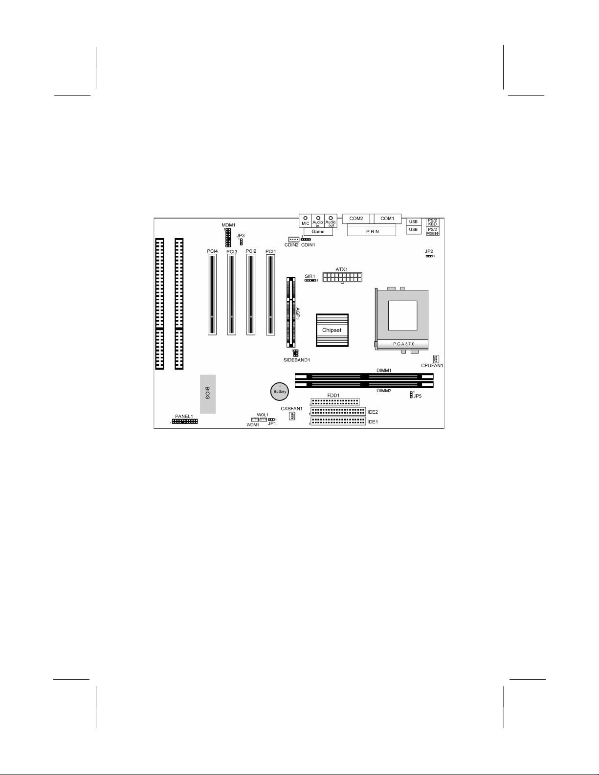
Mainboard Components
Use the diagram below to identify the major components on the
mainboard.
Note: Any jumpers on your mainboard that do not appear in
this illustration are for testing only.
8

2: Mainboard Installation
I/O Ports
The illustration below shows a side view of the built-in I/O ports
on the mainboard.
Install CPU
This mainboard has a Socket-370 which supports PPGA FCPGA
Celeron and FCPGA Pentium III processors.
Do not try to install a Socket 7 processor in the Socket-370. A
Socket 7 processor such as the Pentium-MMX, or the AMD K5/K6
does not fit in the Socket 370.
The following list notes the processors that are currently supported
by this mainboard.
FCPGA Pentium III: 500~1130MHz, FS : 100MHz, 133MHz
PPGA FCPGA Celeron: 300~700MHz, FS : 66 MHz
9

Mainboard User’s Manual
Installing a Socket-370 Processor
A processor installs into the ZIF (Zero Insertion Force) Socket-370
on the mainboard.
1. Locate the Socket-370 and CPUFAN1. Pull the locking lever
out slightly from the socket and raise it to the upright position.
2. On the processor, identify the Pin-1 corner by its beveled edge.
3. On the Socket-370, identify the Pin-1 corner. The Pin-1 corner
is at the end of the locking lever when it is locked.
4. Match the Pin-1 corners and insert the processor into the
socket. No force is required and the processor should drop into
place freely.
5. Swing the locking lever down and hook it under the catch on
the side of the socket. This secures the CPU in the socket.
6. All processors should be installed with a combination heatsink/
cooling fan, connect the cable from the fan to the CPU fan
power connector CPUFAN1.
10
CPUFAN1
Pin-1 Corner
Socket-370
2: Mainboard Installation
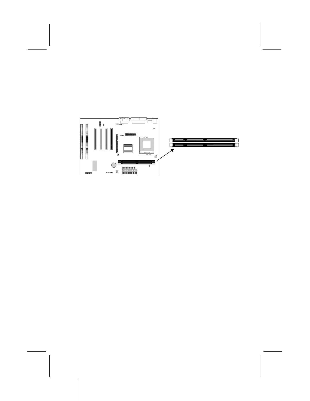
Install Memory
The mainboard has two DIMM sockets for system memory
modules. You must install at least one memory module in order to
use the mainboard.
For this mainboard, you must use 168-pin, 3.3V unbuffered
SDRAM memory modules. If the installed CPU uses a 100MHz
system bus, you must use PC100 or PC133 memory. If the
installed CPU uses a 66MHz system bus, you must use PC66
memory. You can install any size memory module from 8 M to
256M , so the maximum memory size is 2 x 256M = 512 M .
The edge connectors on the memory modules have cut outs, which
coincide with spacers in the DIMM sockets so that memory
modules can only be installed in the correct orientation.
To install a module, push the retaining latches at either end of the
socket outwards. Position the memory module correctly and insert
it into the DIMM socket. Press the module down into the socket so
that the retaining latches rotate up and secure the module in place
by fitting into notches on the edge of the module.
11
DIMM1
DIMM2

Mainboard User’s Manual
Setting Jumper Switches
Jumpers are sets of pins which can be connected together with
jumper caps. The jumper caps change the way the mainboard
operates by changing the electronic circuits on the mainboard. If a
jumper cap connects two pins, we say the pins are SHORT. If a
jumper cap is removed from two pins, the pins are OPEN.
Jumper JP1: Clear CMOS Memory
Use this jumper to clear the contents of the CMOS memory. You
may need to clear the CMOS memory if the settings in the Setup
Utility are incorrect and prevent your mainboard from operating.
To clear the CMOS memory, disconnect all the power cables from
the mainboard and then move the jumper cap into the CLEAR
setting for a few seconds.
Function Jumper Setting
Normal Operation Short Pins 1-2
Clear CMOS Memory Short Pins 2-3
Jumper JP2: Keyboard Power On Selector
If you enable the keyboard power on feature, you can use hot keys
on your keyboard as a power on/off switch for the system.
Note: The system must provide 1A on the +5VSB (+5V Standby)
signal before using the Keyboard ower On function.
Function Jumper Setting
Enable Keyboard Power On Short Pins 1-2
isable Keyboard Power On Short Pins 2-3
12
JP5
JP3
JP1
JP2
1
1
1
1

2: Mainboard Installation
Jumper JP3: Audio System nable/disable Jumper
This 3-pin jumper can be used to enable or disable the onboard
audio system. If you prefer to install a different audio system on a
third party expansion card, you must disable the onboard audio in
order to free up resources for the alternate sound card.
Function Jumper Cap
Enable audio system Short pins 1-2
isable audio system Short pins 2-3
Jumper JP5: 133 MHz System Bus Selector
This mainboard provides CPU Plug and Play technology, so there
is no jumper for the CPU speed setting. ut you need to set the
jumper JP5 as below for a 133 MHz system bus CPU. Then enter
to IOS Setup to set the FS item to 133 MHz.
Function Jumper Setting
66/100 MHz Short Pins 1-2
133 MHz Short Pins 2-3
13

Mainboard User’s Manual
Install the Mainboard
Install the mainboard in a system chassis (case). The board is a
micro-ATX size mainboard with a twin-tier of I/O ports. You can
install this mainboard in any ATX case. Special micro-ATX cases
are also available with a reduced number of expansion slot bays
and a smaller power supply unit. Ensure that your case has an I/O
cover plate that matches the ports on this mainboard.
Install the mainboard in a case. Follow the instructions provided by
the case manufacturer using the hardware and internal mounting
points on the chassis.
1. Connect the power connector from the power supply to the
ATX1 connector on the mainboard.
2. If there is a cooling fan installed in the system chassis, connect
the cable from the cooling fan to the CASFAN1 fan power
connector on the mainboard.
3. Connect the case switches and indicator LEDs to the PANEL1
switch and LED connector header.
14
CASFAN1
ATX1
PANEL1
1

2: Mainboard Installation
See the illustration below for a guide to the PANEL1
connector pin assignments.
15
22
21
Power LED
Pins 2-4-6
S eaker
Pins 1-3-5-7
Keylock
Pins 8-10
HDD LED
Pins 15-16
2
1
Reset Switch
Pins 17-18
Power Button Pins 21-
22
Sus end LED
Pins 13-14
Sus end Switch
Pins 19-20
Mainboard User’s Manual
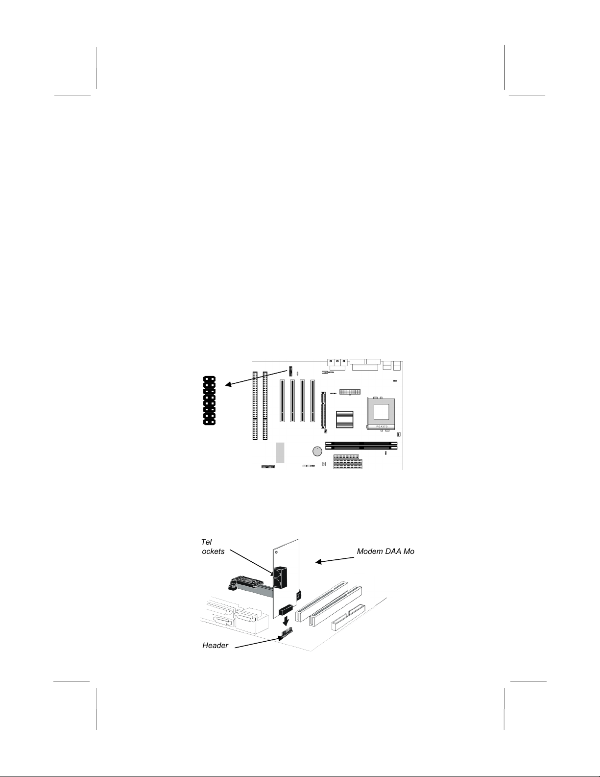
Install the Extension Brackets
The extension brackets are used to connect features on the
mainboard to external connectors that can be attached to the
system chassis. Follow the steps below to install the extension
brackets.
Note: All the ribbon cables used on the extension brackets have a
red stripe on the in-1 side of the cable.
Fax/Modem Module
The Fax/Modem DAA module plugs directly into the mainboard in
line with to an expansion slot opening in the system chassis. When
you remove the slot cover from the system chassis, you can access
the LINE and TEL RJ11 connectors on the metal edge of the Fax/
Modem DAA module.
1. Locate the MDM1 modem header on the mainboard.
2. Plug the Fax/Modem DAA module into the header.
3. Remove the modem header slot cover.
16
Modem DAA Module
Modem Header
Line & Tel
RJ11 Sockets
MDM1-Modem Header
1
This manual suits for next models
2
Table of contents
Other Elpina Motherboard manuals


