Zida GX3D-CM User manual

USER’S
MANUAL
More compatible, more functional and more competitive. Excellent
quality and faster response.
Supporting Intel PENTIUM III
®
, PENTIUM II
®or Celeron
®
Processors, Bus Master IDE, UDMA66, PC100/66 SDRAM,
Integrated VGADisplay Controller.
Quality, Performance Mainboards

c
ontents
Table Of Contents
Overview. . . . . . . . . . . . . . . . . . . . . . . . . . . . . . . . . . . . .5
Fast start installation. . . . . . . . . . . . . . . . . . . . . . . . . . . . .6
Checking the Package Contents. . . . . . . . . . . . . . . . . . . .7
Mainboard diagram. . . . . . . . . . . . . . . . . . . . . . . . . . . . . .9
6 quick steps. . . . . . . . . . . . . . . . . . . . . . . . . . . . . . . . .12
Installing the CPU. . . . . . . . . . . . . . . . . . . . . . . . . . . . . .12
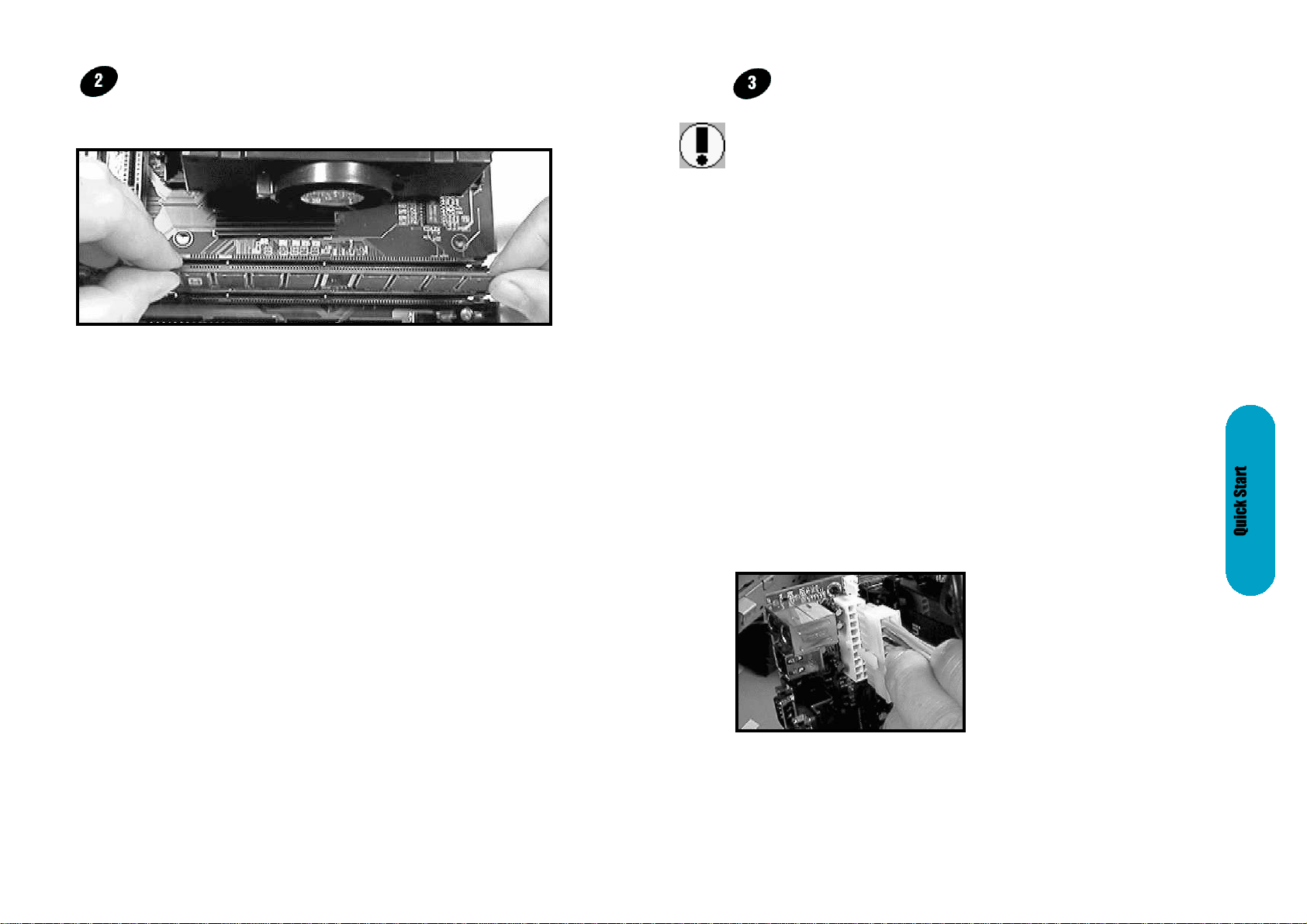
Installing RAM. . . . . . . . . . . . . . . . . . . . . . . . . . . . . . . .14
Attaching power. . . . . . . . . . . . . . . . . . . . . . . . . . . . . . .15
Floppy Drive connector. . . . . . . . . . . . . . . . . . . . . . . . . .16
IDE connector. . . . . . . . . . . . . . . . . . . . . . . . . . . . . . . . .16
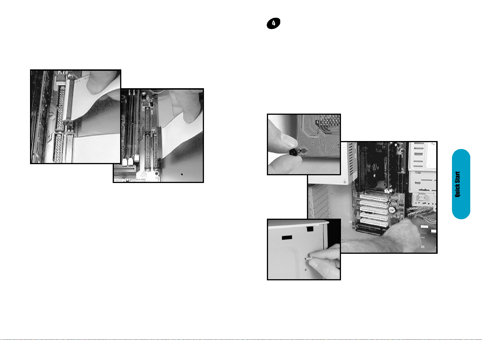
Mounting Mainboard to chassis. . . . . . . . . . . . . . . . . . . .17
Installing COM2 cable connector. . . . . . . . . . . . . . . . . . .18
Installing Add-on Boards. . . . . . . . . . . . . . . . . . . . . . . . .18
Bios set-up. . . . . . . . . . . . . . . . . . . . . . . . . . . . . . . . . . .20
Glossary. . . . . . . . . . . . . . . . . . . . . . . . . . . . . . . . . . . . .39
MainboardUser'sManualPage3
No part of this manual, including the products and software described in it, may be
reproduced, transmitted, transcribed, stored in a retrieval system, or translated into any
language in any form or by any means, except documentation kept by the purchaser for
backup purposes, without the express written permission of MANUFACTURER.
MANUFACTURER PROVIDES THIS MANUAL “AS IS” WITHOUT WARRANTY OF ANY
KIND, EITHER EXPRESS OR IMPLIED, INCLUDING BUT NOT LIMITED TO THE
IMPLIED WARRANTIES OR CONDITIONS OF MERCHANTABILITY OR FITNESS FOR
A PARTICULAR PURPOSE.
IN NO EVENT SHALL MANUFACTURER, ITS DIRECTORS, OFFICERS, EMPLOYEES
OR AGENTS BE LIABLE FOR ANY INDIRECT. SPECIAL, INCIDENTAL, OR
CONSEQUENTIAL DAMAGES (INCLUDING DAMAGES FOR LOSS OF PROFITS,
LOSS OF BUSINESS, LOSS OF USE OR DATA, INTERUPTION OF BUSINESS AND
THE LIKE), EVEN IF MANUFACTURER HAS BEEN ADVISED OF THE POSSIBILITY
OF SUCH DAMAGES ARISING FROM ANY DEFECT OR ERROR IN THlS MANUAL
OR PRODUCT.
Products and corporate names appearing in this manual may or may not be registered
trademarks or copyrights of their respective companies, and are used only for
identification or explanation and to the owners benefit, without intent to infringe
Intel, Pentium, Pentium II, Pentium III are registered trademark of Intel Corporation
SIS is a registered trademark of SIS Silicon Integrated Systems Corp.
IBM, IBM PC, IBM PC/AT, PC-DOS, OS/2 and OS/2 WARP are registered trademarks
of International Business Machines Corporation.
Ms-DOS, Windows, Windows NT, Windows 98 and Windows 95 are registered
trademarks of Microsoft Corporation.
AWARD BIOS is a product of Award Software Inc.
Third-party brands and names mentioned in this User’s Guide are the property of their
respective owners.
The product name and revision number are both printed on the board itself. Manual
revisions are released for each board design represented by the digit before and after
the period of the manual revision number. Manual updates are represented by the third
digit in the manual revision number.
SPECIFlCATlONS AND INFORMATION CONTAINED IN THIS MANUAL ARE
FURNISHED FOR INFORMATION USE ONLY, AND ARE SUBJECT TO CHANGE AT
ANY TIME WITHOUT NOTICE, AND SHOULD NOT BE CONSTURED AS A
COMMiTMENT BY MANUFACTURER. MANUFACTURER ASSUMES NO
RESPONSIBILITY OR LIABILITY FOR ANY ERRORS OR INACCURACIES THAT MAY
APPEAR IN THIS MANUAL, INCLUDING THE PRODUCTS AND SOFTWARE
DESCRIBED IN IT.
Copyright © 1999 Manufacturer All Rights Reserved.
Manual Revision:1.01
Release Date:July 1999
Part No: 90-GXCMX1.01-00
Page2MainboardUser'sManual

overview
Thank You for purchasing our new generation with best
performance mainboard. Our advanced technologies mainboard
designs for state of artprocessor and the processing speed of
233MHz to 500MHz or above. The system board can upgradeable
for future processors.
The SiS chipset integrates the high performance host bus interface,
the DRAM controller, the IDE controller, the PCI interface, 2D/3D
Graphics accelerator and video playback accelerator. The DRAM
controller supports 3-DIMM/6-Bank of 3.3V SDRAM. The maximum
memory size supported per bank is 256MB, with a total of 1.5GB
system memory. The memory clock frequency can be operated at
up to 100MHz.
The IDE controller is ATA-3 compliant, supporting PIO mode
0/1/2/3/4, DMA multiword 0/1/2 and Ultra DMA 33/66 operations.
The two IDE channels are fully independent with dedicated 16
double-word FIFO built-in.
The integrated 3D graphics accelerator is composed of the triangle
setup engine and the rendering engine. The hardware acceleration
features can be enabled by SiS driver under Direct 3D and OpenGL.
The supported 3D-quality acceleration includes Gouroud Shading,
Zbuffer, Alpha buffer, Perspective Correction, MipMaping, Tri-linear
Texture Filtering, Specular Lighting and Dithering.
In UMA mode operation, the integrated graphics accelerator uses
up to 8MB of system memory as display memory, thereby saving the
on-board DRAM cost for building a PC system.
This Mainboard is among our “Auto Jumper” Series that eliminates
the necessity for the user to be overwhelmed by jumper settings on
the Mainboard. It is capable of detecting the CPU brand and core
voltage, setting the appropriate CPU speed according to the
instructions from the user through the CMOS setup.
MainboardUser'sManualPage5

Checking The Package Contents
Remove the items from the box and make sure you have the
following items before beginning. If you are missing any of the
items below please contact the representative for a replacement
part.
MICRO ATXBox Standard Package
1) Mainboard
2) IDE Hard Drive Ribbon Cable
3) Floppy Drive Ribbon Cable
4) Serial Port Cable For COM2
5) CD-ROM
6) Users Guide
Page6MainboardUser'sManual
Faststart
installation
This section will aid you in quickly setting up your series
Mainboard, be sure to use caution to avoid personal injury and
damage to wiring due to sharp pins on connector's and printed
circuit assemblies, rough edges and corners and hot components.
Adhere to warnings regarding accessibility into ares designated
only for authorized Technicians.
Your Location Requirements Are:
• A sturdy, level surface for placement
• Space allowance around mainboard
• A stable environment with no abrupt temperature or
humidity changes
• No exposure to chemicals or direct sunlight
Auto Jumper. This Mainboard is among our “Auto
Jumper” Series that eliminates the necessity for the user
to be Overwhelmed by jumper settings on the Mainboard.
It is capable of detecting the CPU brand and core voltage
setting the appropriate CPU speed according to the
instructions from the user through the CMOS setup.
MainboardUser'sManualPage7

MainboardUser'sManualPage9
BIOS
PCI 3
PCI 2
PCI 1
ISA
CPU SLOT
BOTTOM:
KEYBOARD
USB
VGA
PARALLEL
COM1
TOP:
MOUSE
POWER
SOCKET
FLOPPY
SECONDARY IDE
PRIMARY IDE
DIMM3
DIMM2
DIMM1
AUDIO
CONNECTOR
IDE2IDE1
1
Front Panel
KEYLOCK EXTSMISPEAKER
RESET
PWR .
ON
IDE.
LED
INFRARED
Wakeup-Link
S3
S2
S1
A
C
B
G
U
N
JM
Q
T
K
S
F
OP
E
I
FAN
COM2
x
Y
z
Telephony
CD AudioAuxiliary
(RGGL)
CD Audio
[Digital]
(G,Input)
x*
Mainboard
diagram
Page8MainboardUser'sManual
Before we begin installing your Mainboard we have provided you
with a diagram of the Mainboard to help you locate the appropriate
“connector's” we will make reference to on the Quick Step portion
of this manual. The letters below describes the key Mainboard
components. Page number in the right hand column will direct you
to a detailed description of the component.
CreateGX-MX [PCISoundOnboard]
GX98-MX (WithoutSoundOnboard]
COMPONENTPAGE
A-PS/2 Keyboard / Mouse Connector. . . . . . . . . . . . . . . .40
B-ATX Power Supply. . . . . . . . . . . . . . . . . . . . . . . . . . . .40
C-Universal Serial Bus (USB) Connector. . . . . . . . . . . . .41
E-Infra-Red (IR) connector. . . . . . . . . . . . . . . . . . . . . . . .41
F-Memory Module Sockets . . . . . . . . . . . . . . . . . . . . . . .42
G-Serial COM1, Serial COM2 and
Parallel Port Connector. . . . . . . . . . . . . . . . . . . . . . . .42
I-3V Lithium Battery. . . . . . . . . . . . . . . . . . . . . . . . . . . .42
J-PCI Add-in Board Connector. . . . . . . . . . . . . . . . . . . .43
K-ISA Add-in Board Connector. . . . . . . . . . . . . . . . . . . .43
M-Front Panel Function Connector. . . . . . . . . . . . . . . . . .43
N-Flash BIOS. . . . . . . . . . . . . . . . . . . . . . . . . . . . . . . . .44
O-Floppy Drive Connector. . . . . . . . . . . . . . . . . . . . . . . .44
P-IDE Device Connector. . . . . . . . . . . . . . . . . . . . . . . . .44
Q-WAKEUP-LINK Header. . . . . . . . . . . . . . . . . . . . . . . .45
S-CPU Slot 1. . . . . . . . . . . . . . . . . . . . . . . . . . . . . . . . . .45
T-CPU FAN Connector. . . . . . . . . . . . . . . . . . . . . . . . . .45
U-Audio Connectors. . . . . . . . . . . . . . . . . . . . . . . . . . . . .46
X-CD Audio Connector. . . . . . . . . . . . . . . . . . . . . . . . . .46
Y-Auxiliary Connector. . . . . . . . . . . . . . . . . . . . . . . . . . .46
Z-Telephony Connector. . . . . . . . . . . . . . . . . . . . . . . . . .46

Page10MainboardUser'sManual
Before we begin installing your Mainboard we have provided you
with a diagram of the Mainboard to help you locate the appropriate
“connector's” we will make reference to on the Quick Step portion
of this manual. The letters below describes the key Mainboard
components. Page number in the right hand column will direct you
to a detailed description of the component.
GX3D-CM [PCISoundOnboard]
GX98-CM (WithoutSoundOnboard]
COMPONENTPAGE
A-PS/2 Keyboard / Mouse Connector. . . . . . . . . . . . . . . .40
B-ATX Power Supply. . . . . . . . . . . . . . . . . . . . . . . . . . . .40
C-Universal Serial Bus (USB) Connector. . . . . . . . . . . . .41
E-Infra-Red (IR) connector. . . . . . . . . . . . . . . . . . . . . . . .41
F-Memory Module Sockets . . . . . . . . . . . . . . . . . . . . . . .42
G-Serial COM1, Serial COM2 and
Parallel Port Connector. . . . . . . . . . . . . . . . . . . . . . . .42
I-3V Lithium Battery. . . . . . . . . . . . . . . . . . . . . . . . . . . .42
J-PCI Add-in Board Connector. . . . . . . . . . . . . . . . . . . .43
K-ISA Add-in Board Connector. . . . . . . . . . . . . . . . . . . .43
M-Front Panel Function Connector. . . . . . . . . . . . . . . . . .43
N-Flash BIOS. . . . . . . . . . . . . . . . . . . . . . . . . . . . . . . . .44
O-Floppy Drive Connector. . . . . . . . . . . . . . . . . . . . . . . .44
P-IDE Device Connector. . . . . . . . . . . . . . . . . . . . . . . . .44
Q-WAKEUP-LINK Header. . . . . . . . . . . . . . . . . . . . . . . .45
s-Socket 370 CPUSocket. . . . . . . . . . . . . . . . . . . . . . .47
T-CPU FAN Connector. . . . . . . . . . . . . . . . . . . . . . . . . .45
U-Audio Connectors. . . . . . . . . . . . . . . . . . . . . . . . . . . . .46
X-CD Audio Connector. . . . . . . . . . . . . . . . . . . . . . . . . .46
Y-Auxiliary Connector. . . . . . . . . . . . . . . . . . . . . . . . . . .46
Z-Telephony Connector. . . . . . . . . . . . . . . . . . . . . . . . . .46
MainboardUser'sManualPage11
BIOS
PCI 3
PCI 2
PCI 1
ISA
CPU
SOCKET
BOTTOM:
KEYBOARD
USB
VGA PARALLEL COM1
TOP:
MOUSE
POWER
SOCKET
FLOPPY
SECONDARY IDE
PRIMARY IDE
DIMM3
DIMM2
DIMM1
AUDIO
CONNECTOR
IDE2IDE1
1
Front Panel
KEYLOCKEXTSMI
SPEAKER
RESET
PWR .
ON
IDE.
LED
INFRARED
Wakeup-Link
S3
S2
S1
A
C
B
G
U
N
JM
Q
T
K
s
F
O
P
E
I
FAN
COM2
x
z
Telephony
CD Audio(RGGL)
Socket 370
Y
Auxiliary
PCI 4 (optional)
Mainboard
diagram

CPU Cooling Fan Installation Diagram The recommended
heatsinks for the Pentium II processor are those with three-
pin fans that can be connected to the fan connectors on the
motherboard provides the +12 Volts D.C. for your CPU
cooling fan.
CAUTION! Be sure that sufficient air circulation is available
across the processor’s heatsink by regularly checking that
your CPU fan is working. Without sufficient circulation. the
processor could overheat and damage both the processor
and the motherboard. You may install an auxiliary fan.
if necessary.
Insert the Cartridge: Push the SEC cartridge's two locks
inward. With the heatsink facing the mainboard's chipset,
press this cartridge gently but firmly until it is fully inserted.
The motherboard provides a 370 pins, Socket 370. The CPU
should have a fan attached to it to prevent overheating. If a
fan is not present, user should purchase a fan prior to turning
on the system. The recommended heatsinks for the Socket
370 processor are those with three-pin fans that can be
connected to the fan connectors on the motherboard.
provides the +12 Volts D.C. for your CPU cooling fan.
Installing the Central Processing Unit (CPU)
MainboardUser'sManualPage13
6quick
steps
Please follow these steps in order to assure your series
Mainboard installation is successful. Please refer to the back
chapters for further information regarding boot-up and
configuration. An anti static rist band is recommended when
handling electronic components, be sure your work area is
static free before you begin this section
The Mainboard provides a 242-pin CPU slot.(S in
diagram). The CPU card should have a fan attached to it
to prevent overheating. If a fan is not present, user should
purchase a fan prior to turning on the system. The fan
power connector should be included.
Installing the Central Processing Unit (CPU)
Page12MainboardUser'sManual

MainboardUser'sManualPage15
ATX Power Connector.
ATX Power Supply Connector (20-pin ATXPWR)
The single 20-pin connector (B in diagram) incorporates
standard +5V and +12V, with optional 3.3V soft-on/off
signals. With a power supply that supports remote power
on/off, the mainboard can turn off the system power through
the software control, such as the shutdown in Windows 95
Start Menu. The BIOS system will turn the system power off
when it receives the proper APM command from the OS.
APM must be enabled in the BIOS and OS systems in order
for the soft-off feature is to work properly.
Attaching the power supply ribbon cable
IMPORTANT: Make sure your main power switch is OFF
or remove the power cord. Ribbon cables should always be
connected with the red stripe on the Pin 1 side of the con-
nector. The four corners of the connector's are labeled on the
motherboard. Pin 1 is the side closest to the power
connector on hard drives and floppy drives.
ATX Power Connector
Page14MainboardUser'sManual
After you have set the memory firmly into its slot snap the
white chip holders up to lock in the memory chip. The chart
below will help you determine what slot to use for the
memory configuration you want.
Installing the memory
Memory is installed in DIMM Sockets 1-3 (F in diagram)
as follows.
SDRAMInstallation Sequence
Install SDRAM into the DIMM Slot must according to the
following sequence.
1. DIMM1 Slot ( Must Install First )
2. DIMM2 Slot
3. DIMM3 Slot

MainboardUser'sManualPage17
Installing the mainboard into your computer chassis
Snap black mounting pins onto the mainboard as shown.
Carefully insert the mainboard into the computer chassis
and align the corresponding mounting holes on the
mainboard with the holes on you chassis. While chassis
design varies you may need to refer to the chassis manual for the
mainboard mounting area.Insert white pins through the
chassis and through the mounting holes on the mainboard
into the black pin making sure they have snapped fully
into place.
Black mount pin
Insert into chassis
Insert White mount pin
Page16MainboardUser'sManual
FLoppy Disk Drive Connector (34-pin FLOPPY).
This is a 34-pin connector that supports the provided floppy
drive ribbon cable, After connecting the single end to the
on-board “FLOPPY” connector, (O in diagram) connect the
remaining plugs on the other end to the corresponding
floppy drives.
IDE Connector.
The on-board IDE connector's (P in diagram)support the
provided 40-pin IDE hard disk ribbon cable. After connecting
the single end to the mainboard, connect the remaining plugs
at the other end of your hard disk(s). If you install hard disks,
you must configure the drives by setting its jumpers
according to the documentation of your hard disk.
Also, you may connect the hard disk drives so that both
become Masters, using one ribbon cable on the primary
connector. and the other on the secondary IDE connector.
NOTE: For the flat ribbon cable connection, please make
sure that the pin 1 of the ribbon cable (the red wire side of
the cable) is correctly connected to the on-board connector's
pin 1 as shown on the “diagram the mainboard”.
Floppy connection
IDE connection

MainboardUser'sManualPage19
I/O connector aligned
with openings
Make sure to align rear external I/O connector's with
the corresponding openings in chassis shown below
(A,C & G in diagram)
REMEMBER! This Mainboard is among our “Auto
Jumper” Series that eliminates the necessity for the user
to be overwhelmed by jumper settings on the Mainboard.
It is capable of detecting the CPU brand and core voltage
setting the appropriate CPU speed according to the
instructions from the user through the CMOS setup.
You can now attach the Front Panel
Function Connector (M in diagram)
wires and Keyboard, Mouse and
Monitor cables to the appropriate
serial ports. connect the main power
cable and boot your system.
Boot the system while pressing the
key on your keyboard to detect CPU
speed and auto configure
Mainboard.
Press the DEL key when prompted
and continue BIOS configurations
discussed in the next chapter.
Page18MainboardUser'sManual
PCI Board Installation
Installing PCI Add-in Boards
First read your expansion card documentation for hardware and
software settings that may be required to set up your specific
card. Set any necessary jumpers on your expansion card and
remove the opening cover plate on your computer case at the
slot you intend to use. Keep the plate for possible future use.
Carefully align the card's connector and press firmly. Secure
the card on the slot with the screw you removed from the
cover plate.
Installing COM2 cable connector
The Mainboard provides a COM2 header for the Serial Cable
(Package Included ). First Install the cable header on the
mainboard COM2. Remove the opening cover plate on your
computer case at the place you intend to use. Keep the plate
for possible future use. Carefully align the cable's connector's
and press firmly. Secure the cable on the case with the screw
you removed from the cover plate.

MainboardUser'sManualPage21
Standard CMOS Setup
Bios Features Setup
Chipset Features Setup
Power Management Setup
PCI/PnP Configuration
Integrated Peripheral Setup
Load BIOS Defaults
Load SETUP Defaults
Password Setting
IDE HDD Auto Detection
Sets time, date, hard disk type, types of floppy drive.
Monitor type, and if keyboard is installed.
Sets Typematic Rate and Delay, Above 1 MB
Memory Test, Memory Test Tick Sound, Hit <Del>
Message Display, System Boot Up Sequence, and
many others.
Sets chipset-specific options and features.
Controls power conservation options.
Sets options related to PCI bus and Plug and Play
options.
Controls I/O Controller- related options.
This function is for user to load the BIOS default set-
tings.
This function is for user to load the SETUP default
settings.
The password setting allows you to limit the user
access to the system and Setup.
Automatically configure hard disk parameters.
Award BIOS Setup
BIOS
Set-Up

MainboardUser'sManualPage23
Type
IDE
Standard
MFM
Non-Standard
MFM
How to Configure
Select Type. Select Auto to let BIOS determine the parameters. Click
on OK when BIOS displays the drive parameters. Select LBA Mode.
Select On if the drive has a capacity greater than 540 MB.
Select Block Mode. Select On to allow block mode data transfers.
Select 32-Bit Mode. Select On to allow 32-bit data transfers. Select
the PIO Mode. It is best to select Auto to allow BIOS to determine the
PIO mode. If you select a PIO mode that is not supported by the IDE
drive. The drive will not work properly. If you are absolutely certain
that you know the drive’s PIO mode. Select PIO mode 0-4, as appro-
priate.
Select Type. You must know the drive parameters. Select the drive
type that exactly matches your drive’s parameters.
Select Type. If the drive parameters do not match the drive parame-
ters listed for drive types 1 - 46. Select User and enter the correct
hard disk drive parameters.
Parameter
Type
Cylinders
Heads
Precompensation
Landing Zone
Sectors
Description
The number for a drive with certain identification parameters.
The number of cylinders in the disk drive.
The number of heads.
The actual physical size of a sector gets progressively smaller as the
track diameter diminishes. Yet each sector must still hold 512 bytes.
Write precompensation circuitry on the hard disk compensates for the
physical difference in sector size by boosting the write current for sec-
tors on inner tracks. This parameter is the track number on the disk
surface where write precompensation begins.
This number is the cylinder location where the heads normally park
when the system is shut down.
The number is the cylinder location where the heads normally park
when the system is shut down.
The formatted capacity of the drive is the number of heads times the
number of cylinders times the number of sectors per track times 512
(bytes per sector).
Entering Drive Parameters
Page22MainboardUser'sManual
Standard CMOS Setup
Select the Award BIOS Setup options by choosing Standard Setup from the Award
BIOS. Setup main menu. The Standard CMOS Setup options are described below.
Floppy Drive A: and B:
Move the cursor to these fields and select the floppy type. The setting are 360 KB 5
1/4 inch, 1.2 MB 5 1/4 inch, 720 KB 3 1/2 inch or 2.88 MB 3 1/2 inch.
Primary Master
Primary Slave
Secondary Master
Secondary Slave
Select these options to configure the drive named in the option. Select Auto Detect
IDE to let BIOS automatically configure the drive. A screen with a list of drive parame-
ters appears. Click on OK to configure the drive.

MainboardUser'sManualPage25
BIOS Features Setup
Virus Warning
You can "Enable" or "Disable" this feature. When enabled, it will activate
automatically if anything attempt to access the boot sector or hard disk
partition table during system boot-up. The default value is "Disabled".
CPU Internal Cache
This category enables or disables the internal cache to speed up mem-
ory access. The default value is "Enabled".
External Cache
This category enables or disables the secondary (L2) cache to speed
up memory access. The default value is "Enabled".
CPU L2 Cache ECC Checking
This category enables or disables the CPUL2 cache ECC Checking
procedure. The default value is "Enabled".
Page24MainboardUser'sManual
CPU SPEED Setting
The system BIOS is capable to detect the CPU type, say Pentium III or
Pentium II or Celeron. The user is only required to select the CPU speed. In
addition, overclocking option is provided for advanced users who prefer to run
the CPU over the specified clock frequency.

MainboardUser'sManualPage27
Security Option
This category allows you to limit access to the system and Setup or just to
Setup. When you select system, the system will not boot and access to Setup
will be denied if the correct password is not entered at the prompt. If you
select Setup, the system will boot but access to Setup will be denied if the cor-
rect password is not entered at the prompt. The default setting is "Setup".
PCI/VGA Palette Snoop
This option controls the system to access the PCI VGA card palette register.
In general, this option is "Disabled". However, you may need to enable this
option for some VGA cards which have incorrect color displayed on some
software application.
OS Select For DRAM > 64MB
Some the OS/2 application access the memory in different mode. Enable this
option to allow the system use another mode to access the main memory for
OS/2 applications.
Report No Floppy Disk For Windows 95
The system will report floppy disk status to Windows95 if setting is Yes.
VIDEO BIOS Shadow
The system BIOS is automatically shadowed. The default setting for the
"Video BIOS Shadow" is "Enabled". It determines whether video BIOS will be
copied to RAM. However, it is optional from chipset design. Video Shadow will
increase the video speed.
C8000 - CFFFF Shadow/E8000 - EFFFF Shadow
These categories determine whether optional ROM will be copied to RAM by
16K byte. You can enable the optional shadow or you can disable it. The
default setting is disabled.
Page26MainboardUser'sManual
Quick Power On Self Test
This category speeds up Power On Self Test (POST) after you power on the
computer. If it is set to "Enabled", BIOS will shorten or skip some check items
during POST. The default value is "Disabled".
Boot Sequence
This category determines which drive computer searches first for the disk
operating system (i.e., DOS). The default setting is "A,C,SCSI", means that
the system will determine the drive A before drive C.
Swap Floppy Drive
This feature allows you to enable the system swap floppy function, the default
is "Disabled". When this function enables, the system will assign the Drive A
as Drive B, and vice versa.
Boot Up Floppy Seek
The default setting is "Enabled", so that the BIOS will search for floppy disk
drive to determine if it is 40 or 80 tracks. If disabled, BIOS will not search for
the type of floppy disk drive by track number. Note that there will be no warn-
ing message if the drive installed is 360K.
Boot Up NumLock Status
It determine the Num-Lock is turned on/off Num Lock. when the system is
powered on so that the end user can use the arrow keys on both the numeric
keypad and the keyboard. The default value is "On".
Boot Up System Speed
It selects the default system speed - the speed that the system will run at
immediately after power up. The default value is "High".
Typematic Rate Setting
Typematic Rate sets the rate at which characters on the screen at which char-
acters on the screen repeat. The default setting is Disabled.
Typematic Rate (Chars/Sec)
Typematic rate sets the rate at which characters on the screen repeat when a
key is pressed and held down. You can select 6-30 characters per second.
The default setting is "6".
Typematic Delay (M sec)
When holding down a key, the time between the first and second character
display. you specified numbers of times of character repeat on the screen.
The default setting is "250".

MainboardUser'sManualPage29
RAS to CASDelay
This field sets the RASto CASDelay timing.
The Choice: 2T, 3T, 4T, 5T.
ISA Bus Clock Frequency
This field sets the ISABus Clock Frequency.
The Choice:PCICLK/4, PCICLK/3, 7.159MHz
Starting Point of Paging
This field sets the Starting Point of Paging timing.
The Choice: 1T, 2T, 4T, 8T.
SDRAM CAS latency
This field sets the CAS latency timing.
The Choice: 2T, 3T.
SDRAMWR Retire Rate
This field sets the SDRAMWRRetire Rate.
The Choice: X-1-1-1, X-2-2-2.
CPUto PCIBurst MEM. WR
This field sets the CPUto PCIBurst MEM. WR.
The Choice: Enable,.Disable.
System BIOS Cacheable
Select Enabled allows caching of the System BIOS, resulting in better system
performance.
The Choice:Enable, Disable.
Video RAM Cacheable
Select Enabled allows caching of the video RAM , resulting in better system per-
formance. However, if any program writes to this memory area, a system error
may result.
EnabledVideo RAM access cached
DisabledVideo RAM access not cached
Memory Hole At 15M-16M
In order to improve performance, certain space in memory can be reserved for
ISA cards. This memory must be mapped into the memory space below 16 MB.
EnabledMemory hole supported.
DisabledMemory hole not supported.
Page28MainboardUser'sManual
Chipset Features Setup
Choose Chipset Features Setup on the Setup main menu. All Chipset Setup
options are then displayed.
Auto Configuration
Select the auto configuration setting mode.
The Choice: Enable, Disable
RAS Pulse Width Refresh
This field sets the RASPulse Width Refresh timing.
The Choice: 4T, 5T, 6T, 7T.
RAS Precharge Time
This field sets the RASPrecharge timing.
The Choice: 2T, 3T, 4T, 5T.

Page31MainboardUser'sManual
PCI/PnP Configuration Setup
Choose PCI/Plug and Play Setup from the BIOS Setup screen to display the PCI
and Plug and Play Setup options, described below.
Resources Controlled by
The Award Plug and Play BIOS can automatically configure all the boot
and Plug and Play-compatible devices. If you select Auto, all the inter
rupt request (IRQ) and DMA assignment fields disappear, as the BIOS
automatically assigns them.
The choice: Auto and Manual.
Reset Configuration Data
Normally, you leave this field Disabled. Select Enabled to reset Extended
System Configuration Data (ESCD) when you exit Setup if you have installed a
new add-on and the system reconfiguration has caused such a serious conflict
that the operating system cannot boot.
The choice: Enabled and Disabled.
Page30MainboardUser'sManual
AGP Aperture Size (MB)
Select the size of the Accelerated Graphics Port (AGP) aperture. The aperture is
a portion of the PCI memory address range dedicated for graphics memory
address space. Host cycles that hit the aperture range are forwarded to the
AGP without any translation.
The choice: 4, 8, 16, 32, 64, 128, 256
Concurrent Function (MEM)
When disable, CPU bus will be occupied during the memory operation period.
The choice: Enabled, Disabled.
Concurrent Function (PCI)
When disable, CPU bus will be occupied during the entire PCI operation period.
The choice: Enabled, Disabled.
CPUPipeline Control
This field sets the CPUPipeline Control.
The Choice: Enable,.Disable.
PCIDelay Transaction
This field sets the PCIDelay Transaction.
The Choice: Enable,.Disable.
Auto Detect DIMM / PCIClk
This field sets the auto detection of DIMM/ PCIClock.
The Choice: Enable,.Disable.
Spread Spectrum
This field sets the Spread Spectrum.
The Choice: Disable, 0.25%(Cntr), 0.50%(Down),
CPUHost / SDRAMClock
This field sets the Spread Spectrum.
The Choice: Enable,.Disable.
CPU Clock Ratio Jumpless
The field sets the CPUClock Ratio Jumpless option.
The Choice: Enable,.Disable.
Processor Core Frequency (For Socket 370 models only )
The Choice: x2.0, x3.0, x4.0, x5.0, x6.0, x7.0, x8.0
x1.5, x2.5, x3.5, x4.5, x5.5, x6.5, x7.5

MainboardUser'sManualPage33
Power Management Setup
The BIOS Setup options described in this section are selected by choosing Power
Management Setup from the BIOS Setup main menu.
ACPI function
This item allows you to enable/disable the Advanced Configuration and Power
Management (ACPI).
The choice: Enabled, Disabled.
Power Management
This category allows you to select the type (or degree) of power saving and is
directly related to the following modes:
1. HDD Power Down
2. Doze Mode
3. Suspend Mode
4. Standby Mode
MainboardUser'sManualPage32
IRQ n Assigned to
When resources are controlled manually, assign each system
interrupt as one of the following types, depending on the type of
device using the interrupt:
Legacy ISA Devices compliant with the original PC AT bus speci
fication, requiring a specific interrupt (such as IRQ4 for serial port
1). PCI/ISA PnP Devices compliant with the Plug and Play stan
dard whether designed for PCI or ISA bus architecture.

PM Timers
The following four modes are Green PC power saving functions which are only user
configurable when User Defined Power Management has been selected. See
above for available selections.
HDD Power Down
When enabled and after the set time of system inactivity, the hard disk drive will be
powered down while all other devices remain active.
Doze Mode
When enabled and after the set time of system inactivity, the CPU clock will run at
slower speed while all other devices still operate at full speed.
Suspend Mode
When enabled and after the set time of system inactivity, all devices except the CPU
will be shut off.
The Choice: Instant-Off, Delay 4 Sec.
PM Events
PM events are I/O events whose occurrence can prevent the system from entering
a power saving mode or can awaken the system from such a mode. In effect, the
system remains alert for anything which occurs to a device which is configured as
On, even when the system is in a power down mode.
HDD/ COM /LPT / VGAPorts Activity - Options : Disable / Enable
IRQ [3-7,9-15], NMI - Options : Disable / Enable
IRQ 8 Break Suspend - Options : Disable / Enable
Power Button Over Ride - Options : Delay 4 Sec / Instant Off
Ring Power Up Control - Options : Disable / Enable
LANPower Up Control - Options : Disable / Enable
KBPower Up Control :Disable / Enter /User Define password
KB Power Up by Alarm - Options : Disable / Enable
Month Alarm- Option :1 / 0
Day of Month Alarm - Option :1 ... 31
Week Alarm - Set the optionon/off for *** SUN....SAT***
Time (hh:mm:ss) Alarm - Set the time for Alarm
MainboardUser'sManualPage35
There are three selections for Power Management, three of which have fixed
mode settings.
Disable (default)No power management. Disables all four modes
Min. Power SavingMinimum power management. Doze Mode = 1 hr.
Standby Mode = 1 hr., Suspend Mode = 1 hr., and HDD Power Down = 15
min.
Max. Power SavingMaximum power management -- ONLY AVAILABLE
FOR SL CPU'S. Doze Mode = 1 min., Standby Mode = 1 min., Suspend
Mode = 1 min., and HDD Power Down = 1 min.
User DefinedAllows you to set each mode individually. When not dis-
abled, each of the ranges are from 1 min. to 1 hr. except for HDD Power
Down which ranges from 1 min. to 15 min. and disable.
PM Control APM
When enabled, an Advanced Power Management device will be activated to
enhance the Max. Power Saving mode and stop the CPU internal clock.
If the Max. Power Saving is not enabled, this will be preset to No.
Video Off Option
Selects the power-saving modes during which the monitor goes blank:
Always OnMonitor remains on during power-saving modes.
Suspend --> OffMonitor blanked when system enters Suspend mode.
All Modes --> OffMonitor blanked when system enters any power saving
mode.
Video Off Method
This determines the manner in which the monitor is blanked.
V/H SYNC+BlankThis selection will cause the system to turn off the verti
cal and horizontal synchronization ports and write blanks
to the video buffer.
Blank ScreenThis option only writes blanks to the video buffer.
DPMSInitial display power management signaling.
Page34MainboardUser'sManual

IDE HDD Block Mode
This allows your hard disk controller to use the fast block mode to transfer data to
and from your hard disk drive (HDD).
EnabledIDE controller uses block mode.
DisabledIDE controller uses standard mode.
IDE Primary/Secondary Master/Slave PIO
The four IDE PIO (Programmed Input/Output) fields let you set a PIO mode (0-4) for
each of the four IDE devices that the onboard IDE interface supports. Modes 0
through 4 provide successively increased performance. In Auto mode, the system
automatically determines the best mode for each device.
IDE Primary/Secondary Master/Slave UDMA
Ultra DMA/33 implementation is possible only if your IDE hard drive supports it and
the operating environment includes a DMA driver (Windows 95 OSR2 or a third-
party IDE bus master driver). If your hard drive and your system software both sup-
port Ultra DMA/33, select Auto to enable BIOS support.
The Choice: Auto, Disabled
Init Display First
This item allows you to decide to active PCI Slot or AGP first
The choice: PCI Slot, AGP.
Onboard FDD Controller
This should be enabled if your system has a floppy disk drive (FDD) installed on the
system board and you wish to use it. Even when so equipped, if you add a higher
performance controller, you will need to disable this feature.
The Choice: Enabled, Disabled.
USB Controller The Choice: Enabled, Disabled.
USBKey board Support The Choice: Enabled, Disabled.
VGA Shared Memory Size - Set the VGAShared Memory Size option.
The Choice: None, 2 , 4, 8 MB
Onboard 3DSound - Set the Onboard 3DSound option.
The Choice: Enabled, Disabled.
( Thisis only For Onboard sound Series )
MainboardUser'sManualPage37
Integrated Peripheral Setup
Integrated Peripheral Setup options are displayed by choosing Peripheral Setup form
the BIOS Setup main menu. All Peripheral Setup options are described here.
Internal PCI / IDE
The chipset contains a PCI IDE interface with support for two IDE chan-
nels. Select Enabled to activate the first and/or second IDE interface.
Select Disabled to deactivate an interface, if you install a primary and/or
secondary add-in IDE interface.
The choice: Both, Disabled.
IDE Burst Mode
The onboard IDE drive interfaces supports IDE prefetching, for faster
drive accesses. If you install a primary and/or secondary add-in IDE inter-
face, set this field to Disabled if the interface does not support prefetch-
ing.
The choice: Enabled, Disabled.
Page36MainboardUser'sManual

glossary
Onboard Serial Port 1/Port 2
This item allows you to determine access onboard serial port 1/port 2 controller with
which I/O address.
The Choice: 3F8/IRQ4, 2F8/IRQ3, 3E8/IRQ4, 2F8/IRQ3, Disabled, Auto.
IR IRQ Address
The Choice: Disable, 3F8H, 2F8H
IR Mode
This item allows you to determine which Infra Red (IR) function of onboard I/O chip.
The Choice: Standard, ASKIR, HPSIR.
IR IRQ Select
The Choice: Disable, IRQ3,IRQ4,IRQ10,IRQ11
Onboard Parallel Port Mode
Select an operating mode for the onboard parallel (printer) port. Normal EPP
(Extended Parallel Port) ECP (Extended Capabilities Port) CEP+EPP PC AT paral-
lel port Bidirectional port Fast, buffered port Fast, buffered, bidirectional port.
Select Normal unless you are certain your hardware and software both sup
Onboard Parallel Port
Select a logical LPT port name and matching address for the physical parallel
(printer) port.
The choice: 378H/IRQ7, 278H/IRQ5, 3BCH/IRQ7, Disabled.
port EPP or ECP mode.
Choices are SPP, ECP/EPP, ECP, EPP/SPP.
ECP Mode Use DMA
Select a DMA channel for the port.
Choices are 3, 1.
Parallel Port EPP Type
Select EPP port type 1.7 or 1.9.
Choices are EPP1.7, EPP1.9
Page38MainboardUser'sManual
This manual suits for next models
1
Table of contents
Other Zida Motherboard manuals