Elseta IOMOD HT User manual


Elseta are UAB Elseta trademark that identifies of UAB Elseta manufactured. All of the product and the user manual of
the right to ownership of the copyright belongs to "Elseta". These documents and the product properties can not be
changed without company Elseta' knowledge and written consent. User manual may not be modified without company
Elseta' notice.
Copyrights and trademarks

(in accordance with ISO / IEC Guide 22 and EN Section 45014) Manufacturer: UAB Elseta Address of the manufacturer
L. Zamenhofo st. 5 LT Vilnius, Lithuania
We claim that: The device IOMOD HT
Conforms to the following standards: EMC: Radiation EN 55022 (Class A) 1 emitted radiation (30-1000MHz) Second
radiation conductors (0.15-30MHz) EN 50082-1 immunity test 1 IEC 801-3: Radio-frequency electromagnetic field 2 IEC
801-2: Electrostatic discharge. 3 IEC 801-4: Quick periodic electrostatic discharges
Additional information: "The device complies with the Low Voltage Directive 73/23 / EEC and EMC Directive 89/336 /
EEC. Device assembly complies with the RoHS ROHS Directive.
Manufacturer contact: Equipment quality controller UAB Elseta Address: L. Zamenhofo g. 5, LT 06332, Vilnius, Lithuania
Phone: +370 5 2032302 E-mail. Email: support@elseta.com
Declaration of Conformity

This equipment Operating notes, which must be met for your personal safety, as well as to avoid damage to the
equipment. These notes are marked with a warning triangle symbol and the various degrees of risk of falling within
signs. All work related to electronic systems design, installation, commissioning, adjustment and maintenance should
be carried out in accordance with the safety requirements.
Safety Requirements

Danger - important notice, which may affect the safety of the user or device.
Attention - notice on possible problems that may arise in individual cases.
Information Notice - the information that is useful advice or special places.
Warning of the danger. The work may be performed only by a qualified professional. Equipment installation,
commissioning and maintenance may only be performed by a qualified professional. If the safety notes in this manual,
the term refers to persons qualified specialists authorized to perform commissioning, grounding and labeling devices,
systems and circuits. The person must: Be aware of occupational safety in the workplace. Need to understand the
equipment components. Electrical equipment. Have the knowledge and skills to identify a component beneath the
voltage.
To maintain the equipment necessary to always turn off the power supply before installing or dismantling works. It
must be in mind that even though alone equipment, but can have a common ground connection. Always before
connecting the power supply, cables and interconnect components must be inspected.
This product can not be implemented, or resold to install in areas that are high-security as nuclear power plants,
aircraft navigation, military equipment, transport traffic in management. In areas where equipment failure can result in
of nature and human injury.
Do not operate the equipment in extreme weather conditions, as they may affect the operation of the equipment.
Equipment's Manual Uses Symbols

Introduction
IOMOD HT is used for temperature and humidity data monitoring and relay control over Modbus. Device is also
capable of switching relays automatically (thermostat function) as configured.
Features
• Temperature and humidity sense with ±0,1 % and ±0,1 °C accuracy;
• Temperature sensing range from -10 up to 60 °C;
• Humidity sensing range from 0 to 100%;
• Two Relays which can be configured to turn on automatically on humidity or temperature triggers (only Advanced
version);
• Relays automation configuration over USB or Modbus;
• Configurable Modbus settings, such as Slave ID, Baudrate, Parity and stop bits, RS485 terminating resistor, etc.
• Firmware Upgrade over USB;
• Two connectors for power supply and for RS485, for easier device connection on one line;
Device working information
IOMOD uses Modbus (RTU) protocol over RS485 connection, which can be used with cable length up to 1500 meters
and connect up to 30 devices on one line. Default Modbus settings are: 9600 baudrate, 8N1, Slave address - 1.
To read temperature and humidity, user can use device with default settings without configuring it. To read humidity,
send 04 Modbus command (Read Input Registers) with resolution of first register (0). Returned value will be measured
in % and will be multiplied by 10, to show one decimal place. To read temperature, send 04 (Read Input Registers)
with resolution of second register (1).
Returned value will be measured in °C and will be multiplied by 10. To enable thermostat function, user can configure
device over USB or over MODBUS. Configurable options shown in table below.
CONFIGURABLE OPTIONS
OVER USB
OVER MODBUS
Slave Address
Yes
No
Baudrate
Yes
No
Data, Stop and Parity bits
Yes
No
RS485 Terminating Resistor
Yes
No
1st Relay active mode
Yes
Yes
1st Relay active range
Yes
Yes
2nd Relay active mode
Yes
Yes
2nd Relay active range
Yes
Yes
Default Settings
Yes
No
Introduction - Features - Device
working information - Supported
MODBUS functions

Supported MODBUS functions
01 (0x01) Read Coils Status
Reads status of relays (Off or On). IOMOD HT has 2 relays on addresses 6 and 7 (Only for IOMOD
HT Advanced).
03 (0x03) Read Holding Registers
Reads current configuration of relays. Address 2 – Active Mode for 1st relay ( 0 – disabled, 1 - humidity or 2 -
temperature); Address 3 – Lower Active value (minimal value for relays to turn on) for 1st relay; Address 4 – Upper
Active value (maximum value for relays to keep turned on. If parameter reaches threshold bigger than this value, relay
is turned off) for 1st relay. Address 5 – Active Mode for 2nd relay (humidity or temperature); Address 6 – Lower Active
value (minimal value for relays to turn on) for 2nd relay; Address 7 – Upper Active value (maximum value for relays to
keep turned on. If parameter reaches threshold bigger than this value, relay is turned off) for 2nd relay.
04 (0x04) Read Input Registers
Reads current Humidity and Temperature status. Address 0 – Humidity; Value is multiplied by 10 to show one decimal
place. For example: 23.3 °C will be shown as 233; 50.0 % will be shown as 500 in the Registers.
05 (0x05) Write Single Coil
(Only for IOMOD HT Advanced). Sets single relay On or Off. 1 Relay address – 6th register; 2 relay – 7th register.
06 (0x06) Preset Single Register
Sets single configuration (Only for IOMOD HT Advanced). Address 2 – Active Mode for 1 relay: 0- disabled; 1 - humidity
or 2 - temperature; Address 3 – Lower Active value (minimal value for relays to turn on) for 1 relay; Address 4 – Upper
Active value (maximum value for relays to keep turned on. If parameter reaches threshold bigger than this value, relay
is turned off) for 1 relay. Integer; Address 5 – Active Mode for 2 relay: 0- disabled; 1 - humidity or 2 - temperature;
Address 6 – Lower Active value (minimal value for relays to turn on) for 2 relay; Address 7 – Upper Active value
(maximum value for relays to keep turned on. If parameter reaches threshold bigger than this value, relay is turned
off) for 2 relay.

System
1.
Dimensions
26 (H) x 71 (W) x 71 (L), mm
2.
Case
ABS, white
3.
Working environment
Indoors
4.
Working temperature
-20 ÷ +70°C
5.
Recommended operating conditions
5 – 60°C and 20 – 80%RH;
6.
Configuration
USB or Modbus
7.
Firmware upgrade
USB – mass storage device
Electrical Characteristics
Basic
Advanced
8.
Termination Resistor
Selectable 120Ω
Selectable 120Ω
9.
Power supply
12-24VDC, 8mA (nominal); 5-
33VDC (full range)
24VDC, 25mA (nominal); 18-
27VDC (full range)
10.
Relays
-
2 (Normally Open);
Relay specifications
Basic
Advanced
12.
Resistive load (cosφ=1)
-
5 A at 250 VAC, 5 A at 30 VDC
13.
Inductive load (cosφ=0.4,
L/R=7ms)
-
2 A at 250 VAC, 2 A at 30 VDC
14.
Max. switching power
-
1,250 VA, 150 W
Technical Information

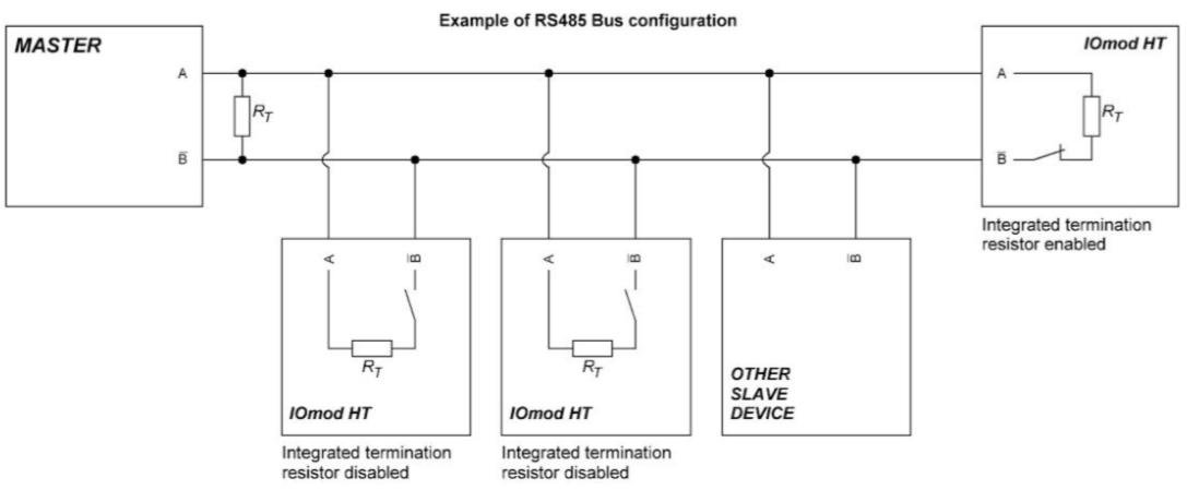
IOMOD HT has integrated 120Ω termination resistor which can be enabled or disabled over USB configuration. It is
recommended to use termination at each end of the RS485 cable. See typical connection diagram on Fig. 5.1.
Fig. 5.1.
IOMOD 8DI8DO has 1/8 Unit load receiver which allows to have up to 256 units on line (compared to standard 32
units). To reduce reflections, keep the stubs (cable distance from main RS485 bus line) as short as possible when
connecting device. Figure 5.2 shows explanation on device connection.
Fig. 5.2
Device connection

a. Driver installation
Device requires USB drivers to work as virtual com port. First-time connection between device and computer could
result in “Device driver software was not successfully installed” error.
Fig. 6.1
User then manually installs drivers by selecting downloaded driver folder:
Go to Control Panel -> Device Manager;
Select failed device;
Press “Update driver software”; following screen should appear:
Fig. 6.2
Select “x86” driver for 32bit machine, or x64 for 64bit machine. If not sure, select root folder (folder in which x64 and
x86 lays inside).
Fig. 6.3
b. IOMOD HT configuration with PuTTY terminal
Configuration of IOMOD device is done through CLI (Command Line Interface) on virtual COM port. Drivers needed for
MS Windows to install VCOM will be provided. To open up CLI simply connect to specific V-COM port with terminal
software (advised to use PuTTY terminal software. If other software is being used, user might need to send <return>
symbol after each command). When connected user should immediately see main screen:
Configuration over USB

Fig. 6.4
Navigation is performed by sending number to terminal. User then proceeds by following further on-screen
instructions. For example, to set Baudrate, press [2] to enter Baudrate screen; press [1] to edit; enter new
configuration; press [RETURN] to save, or [ESC] to cancel changes. When done, press [0] (exit) before disconnecting
device. Default values is set by pressing [7] on main screen, and confirming changes [1]. If accidentally closed the
terminal window, user can connect terminal program again, and press any key on keyboard to show up main menu.
c. Main Menu
Main Menu
Function
Values
Default Values
1.
Slave Address
Modbus Slave address / ID
1-247
(default: 1)
2.
Modbus Baudrate
Modbus Baudrate
100 - 256000
(default: 9600)
3
3.
Data, Stop and Parity bits
Chooses Stop and parity
bits to use
(default: 8N1)
4
4.
RS485 Terminating
Resistor
RS485 120 Ohms
Terminating Resistor
0 - 1 (off/on)
(default: 0)
5.
Relay #1 settings
Active mode and active
range
Active mode: 1 –Relay
disabled; 2- Temperature
active 3- Humidity active;
active range: -10 to 60
(temperature) and 0 to 100
(humidity)
(default: 0)
6.
Relay #2 settings
Active mode and active
range
Active mode: 1 –Relay
disabled; 2- Temperature
active 3- Humidity active;
active range: -10 to 60
(temperature) and 0 to 100
(humidity)
(default: 0)
7.
Set Default Settings
Sets Default Settings
(1 to confirm, 0 to cancel)
-
8.
Firmware Upgrade
Mass Storage Device
Firmware Upgrade
(1 to confirm, 0 to cancel)
-
0.
Exit
Exit and disconnect
-
-
d. Firmware upgrade over USB
To update device firmware user must enter main configuration menu.
Enter Firmware update screen by pressing [4];
Confirm update by pressing [1];
Device now enters Firmware Upgrade mode.

It is recommended to close terminal window when entered firmware upgrade mode.
Device reconnects as mass storage device:
Fig. 6.5
User then must delete existing file “firmware.bin”, and simply upload new firmware file by drag and drop.
Fig. 6.6
Reconnect device, and check firmware version.
e. Testing With “THE VINCI” software
To test IOMOD HT with default settings, user connects device through RS485 to Modbus master. Example will show
“The Vinci Expert” as serial interface converter and adapter to PC with “The Vinci” software. Default settings for
Modbus – 9600 baudrate; 8 data, no parity, 1 stop bit. When opening “The Vinci” software, choose Modbus serial –
Master mode. In settings tab, choose station number (default – 1); configure tags (as described in section 2. Device
working information); Press start and go to “Statistic” tab:
Fig. 6.8


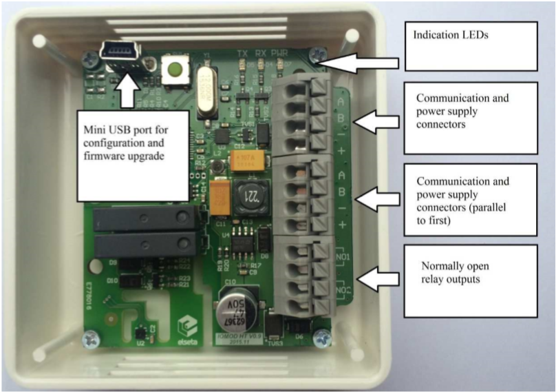
IOmod HT (Humidity and Temperature)
Device picture
Other manuals for IOMOD HT
1
Table of contents
Other Elseta Accessories manuals


