ELSKY QM8U User manual

SHENZHEN ELSKY TECHNOLOGY CO.,LTDwww.miniboard.cn
- 2 -
VGA + single lan port picture↓(default)
――――――――――――――――――――――――――――――――――――――――――――――――――――――
VGA + dual lan port picture↓
――――――――――――――――――――――――――――――――――――――――――――――――――――――
DP + single lan port picture↓
――――――――――――――――――――――――――――――――――――――――――――――――――――――
DP + dual lan port picture↓
――――――――――――――――――――――――――――――――――――――――――――――――――――――
――――――――――――――――――――――――――――――――――――――――――――――――――――――

SHENZHEN ELSKY TECHNOLOGY CO.,LTDwww.miniboard.cn
- 5 -
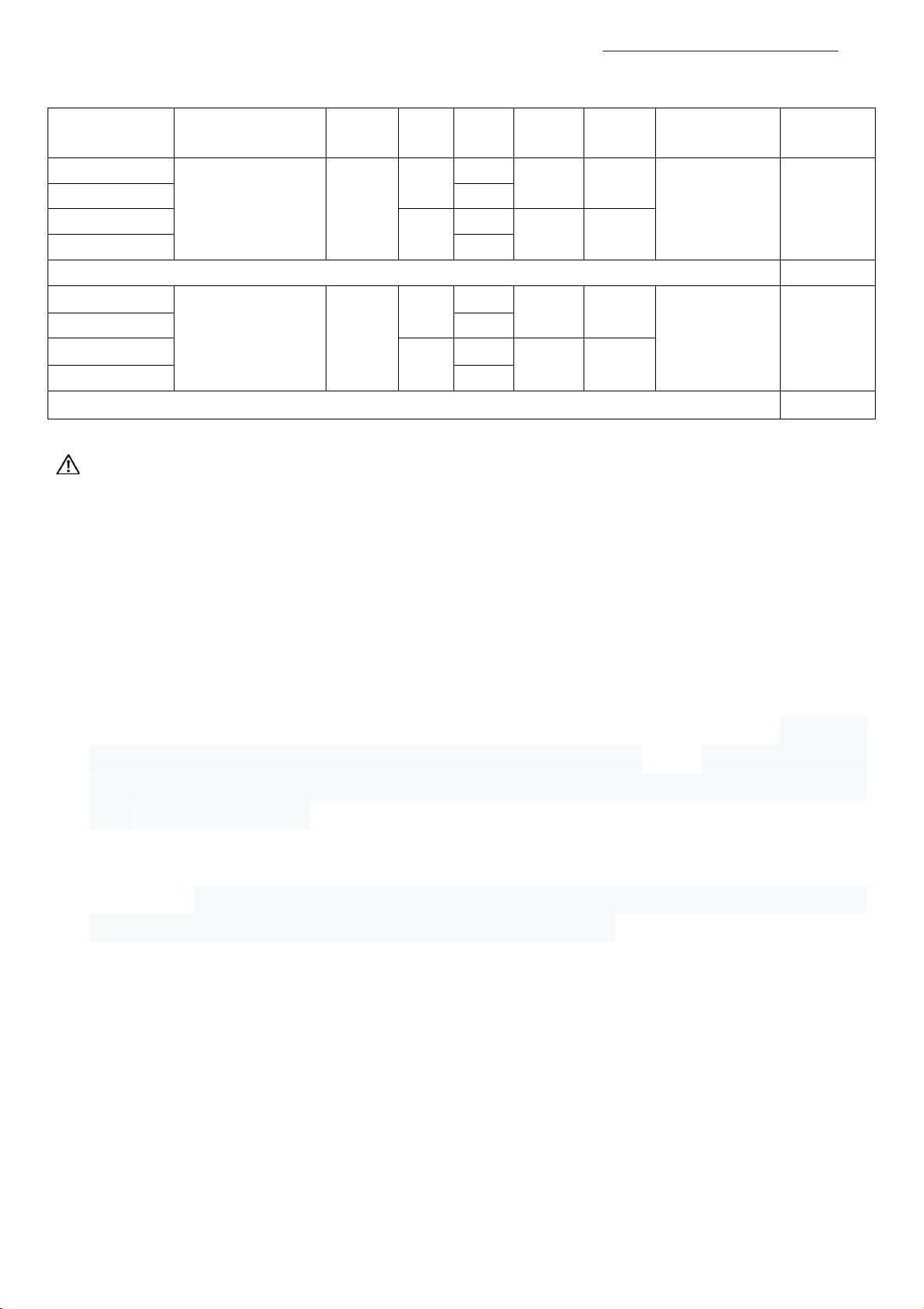
Product Model Order Selection:
Motherboard
model
CPU
4K
LAN
COM
USB2.0
USB3.1
Memory
Power
QM8U-2C
Support Whiskey
Lake 8th gen core
i3、i5、i7
support
1
2
6
4
2*NB DDR4
MAX 64GB
+12V
QM8U-6C
6
QM8U-2L2C
2
2
4
4
QM8U-2L6C
6
Support DP port motherboard model,QM8U-DP specification same as above
QM10U-2C
Support Comet
Lake 10th gen core
i3、i5、i7
support
1
2
6
4
2*NB DDR4
MAX 64GB
+12V
QM10U-6C
6
QM10U-2L2C
2
2
4
4
QM10U-2L6C
6
Support DP port motherboard model,QM10U-DP specification same as above
Important Tips:
1) Motherboard default HDMI+VGA+LVDS+6COM+10USB+1LAN;
2) Motherboard VGA port and DP port two for one choice port ,default support VGA port,can
change support DP port;DP port support 4K resolution 4096/3840*2160@60Hz;
3) Motherboard LVDS pin and EDP pin is two for one choice pin ,by default support LVDS pin,
can change support EDP pin;EDP support 4K resolution 4096/3840*2160@60Hz;
4) Motherboard HDMI port support 4K resolution 4096/3840*2160@30Hz;
5) Motherboard by default support M.2 2280,can choose M.2 2242;Support SATA protocal or
NVME (PCIE)protocal M.2 disk,default support 2types signal;
6) Motherboard MINI-PCIE by default support PCIE signal and USB signal coexist, by default
F_USB2 2/4/6/8/10 pin has no signal,MINI-PCIE USB signal and F_USB2 signal two for one
choice, in which PCIE signal can change to SATA signal,support MSATA disk, SATA1 interface
after the change no signal;
7) Motherboard blue USB port and pin support USB3.1 Gen2,the max transmission broadband
is10.0Gbps;
8) External USB ports and all USB pins will be A power by default (with electricity after shutdown),
all can change to S power (without electricity after shutdown);later manufacture the board
default all USB port and pin will be S power;
9) Motherboard support 6 COM port,can choose 2 COM,COM2~COM6 support RS232;COM1
support RS232/RS422/RS485 optional setting through BIOS;
10) Motherboard COM1 and COM2 can set the 9th pin to output 0V/5V/12V through JCOM1 and
JCOM2 jumping cap respectively, with the default 0V;
11) The motherboard supports single gigabit network port by default, which can be changed to
double gigabit network port;
12) Motherboard only support 12V power supply,not support 19V power supply

SHENZHEN ELSKY TECHNOLOGY CO.,LTDwww.miniboard.cn
- 6 -
CPU information
CPU model
CPU brand
CPU
Frequency
Max Turbo
Frequency
GHz
CPU TDP(W)
8th gen I3
core
8145U
Dual core 2.1G
3.9G
15
8th gen I5
core
8365U
Quad core
1.6G
4.1G
15
8265U
Quad core
1.6G
3.9G
15
8th gen I7
core
8665U
Quad core
1.9G
4.8G
15
10th gen I3
core
10110U
Dual core 2.1G
4.1G
15
10th gen I5
core
10310U
Quad core
1.7G
4.4G
15
core
10210U
Quad core
1.6G
4.2G
15
10th gen I7
core
10510U
Quad core
1.8G
4.9G
15
core
10610U
Quad core
1.8G
4.9G
15
core
10810U
Six core1.1G
4.9G
15
core
10710U
Six core1.1G
4.7G
15
Motherboard Specification
Motherboard
size
170mm*170mm*18mm
CPU
Support 8th gen Whiskey Lake CPU:I3-8145U、I5-8265U、I7-8665U etc.
Support 10th gen Comet Lake CPU:I3-10110U、I5-10210U、I7-10510U etc.
Memory
QM8U
2*NB-DDR4 memory channel ,support 2133/2400MHz memory ,max
support 64GB
QM10U
2*NB-DDR4 memory channel,support 2133/2400/2666MHz memory,
max support 64GB
Power supply
1*DC_IN
Support 12V power,DC head diameter 2.5MM
Motherboard full consumption power is about 85W.Suggest use 12V7A
or above power
1*DC_ATX
Display
function
Integrated Intel UHD Graphics super core graphics controller,Support single display, double
display/three display copy, double display/three display extension, DOS single display
1*VGA_OUT pin
Support resolution 1920*1080@60HZ (12Pin,1*12Pin,
2.0mm)
1*VGA DB15 port
Support resolution 1920*1080@60HZ
1*DP port
Support 4K resolution 4096/3840*2160@60HZ
VGA port and DP port two for one choice

SHENZHEN ELSKY TECHNOLOGY CO.,LTDwww.miniboard.cn
- 7 -
1*HDMI 1.4 port
Support 4K resolution 4096/3840*2160@30HZ
1*HDMI_CON pin
Support 4K resolution 4096/3840*2160@30HZ (16Pin,2*8Pin,
2.0mm)
1*EDP pin
Support 4K resolution 4096/3840*2160@60HZ (30Pin,2*15Pin,
2.0mm)
1*EDP_PWR pin
EDP working voltage control Pin (6Pin,
2*3Pin,2.0mm)
1*LVDS pin
Support resolution 1920*1080@60HZ (30Pin,2*15Pin,
2.0mm)
1*LVDS_PWR pin
LVDS working voltage control pin (6Pin,
2*3Pin,2.0mm)
1*INVERT pin
LVDS Backlight switch backlight brightness control (6Pin,
1*6Pin,2.0mm)
1*BKLT-PWR1
LVDS backlight voltage control pin
LVDS pin and EDP pin two for one choice
Ethernet
function
1*LAN port
Realtek 8111H Gigabit network card chip,Support Network wake-up
and PXE No disk startup function
1*Mini-PCIE port
Support WIFI/3G/4G/GPS/bluetooth module,can choose support MSATA
Hard disk
function
1*M.2 port
By default support M.2 2280,can choose 2242;By default NVME(PCIE)
Agreement, can change support SATA Agreement
1*SATA1 port
标准 SATA3.0 硬盘 port,最大传输速度 6.0 Gbps
SATA1signal and MSATA signal two for one choice,by default support SATA1
1*SATA2 port
Standard SATA3.0hard disk port,Maximum transmission speed 6.0 Gbps
1*SATA_PWR1 pin
It is hard disk power supply pin and can take the 5V,12V electricity.
(4Pin,1*4Pin,2.54mm)
1*SATA_PWR2 pin
It is hard disk power supply pin and can take the 5V,12V electricity.
(4Pin,1*4Pin,2.54mm)
Audio Function
Integrated Realtek ALC662 HD Digital audio decoder, 6-channel high fidelity audio controller
1*LINE_OUT port
Support Audio output(green)
1*MIC_IN port
Support Microphone input(red)
1*INT_SPK pin
power amplifier Support 8Om5W Speaker output (4Pin,
1*4Pin,2.0mm)
1*F_AUDIO pin
Standard Audio Pin (9Pin,2*5Pin,
2.54mm)
1*SPDIF pin
Digital audio pin pin (3Pin, 1*3Pin ,
2.54mm)
USB Function
2*USB3.1 port
Rear standard USB3.1 Gen2 port , Maximum transmission speed
10.0Gbps
2*USB2.0 port
Rear standard USB2.0 port , Maximum transmission speed 480Mbps
(60MB/s)
1*F_USB1 pin
Front USB2.0 pin,one group have 2*USB2.0 (9Pin,2*5Pin,
2.54mm)
1*F_USB2 pin
Front USB2.0 pin,one group have 2*USB2.0 (9Pin,2*5Pin,
2.54mm)
1*F_USB3_A pin
Front USB3.1 Gen2 pin,one group have 2*USB3.1 (19Pin,
2*10Pin,2.0mm)
Switch Function
1*F_PANEL pin
switch、power LED、 Hard disk LED、restart pin (9Pin,
2*5Pin,2.54mm)
1*AUTO_SW pin
hardware control power on pin (3Pin,1*3Pin,

SHENZHEN ELSKY TECHNOLOGY CO.,LTDwww.miniboard.cn
- 8 -
2.0mm)
Other I/O
COM1/COM2 pin
Serial port,COM1 support RS232,RS422/RS485 optional (9Pin,
2*5Pin,2.54mm)
COM3~COM6 pin
Serial port,support standard RS232; (39Pin,
2*20Pin,2.0mm)
1*JCOM1 pin
Control COM1 9th voltage 0V/5V/12V optional (6Pin,
2*3Pin,2.0mm)
1*JCOM2 pin
Control COM2 9th voltage 0V/5V/12V optional (6Pin,
2*3Pin,2.0mm)
1*SIM_CARD card
slot
Support SIM card,when use 3G/4G need SIM card
1*FAN2 pin
CPU fan pin,support temperature control (3Pin,
1*3Pin,2.54mm)
1*FAN3 pin
System fan pin,full speed,not support temperature control
(3Pin,1*3Pin,2.54mm)
1*CLR_CMOS pin
CLR_CMOS Motherboard zero clearing 、 discharge pin
(3Pin,1*3Pin,2.0mm)
1*J_GPIO pin
GPIO control pin (10Pin,2*5Pin,
2.0mm)
Working
environment
working temperature :-20℃~60℃; Working humidity:5%~95% relative humidity, No
condensation
BIOS
AMI BIOS,Support Power up,RTC,Intelligent identification of remote switching equipment
Watch Dog
Watchdog programming,Support Hardware reset function(256level,0~255second)
Operating
system
Support Windows 10 64,Linux etc.

SHENZHEN ELSKY TECHNOLOGY CO.,LTDwww.miniboard.cn
- 11 -
2.1 VGA pin definition:
Item:VGA_OUT (1*12Pin,2.0mm)
pin
Definition
pin
Definition
1
GND
2
VSYNC
3
HSYNC
4
GND
5
RED
6
GND
7
GRN
8
GND
9
BLUE
10
GND
11
DDC_DATA
12
DDC_CLK
pin Bit Number Map
Note: VGA_H pin signal and the rear VGA interface are the same signal, only double-display and
three-display replication is supported.
2.2 HDMI pin definition:
item:HDMI_CON (2*8Pin,2.0mm)
Pin item picture
pin
Definition
pin
Definition
1
HDMI_TXD2P
2
HDMI_TXD1P
3
HDMI_TXD2N
4
HDMI_TXD1N
5
GND
6
GND
7
HDMI_TXD0P
8
HDMI_TXC0P
9
HDMI_TXD0N
10
HDMI_TXC0N
11
GND
12
HDMI_5V
13
HDMI_CLK
14
HDMI_5V
15
HDMI_DATA
16
HDMI_HPD
Notice: When inserting the HDMI cable, the first stitch of the HDMI cable must correspond to the first pin of the
motherboard pin. If the plug is reversed or inserted incorrectly,the screen will not be displayed.

SHENZHEN ELSKY TECHNOLOGY CO.,LTDwww.miniboard.cn
- 12 -
2.3 LVDS pin definition:
item:LVDS (2*15Pin,2.0mm)
Pin item picture
pin
Definition
pin
Definition
1
VCC
2
VCC
3
VCC
4
GND
5
GND
6
GND
7
ADO0-
8
ADO0+
9
ADO1-
10
ADO1+
11
ADO2-
12
ADO2+
13
GND
14
GND
15
ACLK-
16
ACLK+
17
ADO3-
18
ADO3+
19
BDO0-
20
BDO0+
21
BDO1-
22
BDO1+
23
BDO2-
24
BDO2+
25
GND
26
GND
27
BCLK-
28
BCLK+
29
BDO3-
30
BDO3+
Notice: When inserting the LVDS cable, the first stitch of the LVDS cable must correspond to the first pin of the
motherboard pin. If the plug is reversed or inserted incorrectly, there is a danger of burning the screen and burning
the motherboard!
2.3.1 Backlight power supply definition:
item:INVERT (1*6Pin,2.0mm)
Pin item picture
pin
Definition
1
+12V
2
+12V
3
ON/OFF((Backlight switch)
4
ADJ(Backlight brightness adjustment)
5
GND
6
GND
2.3.2 LVDS screen working voltage:
item:LVDS_PWR (2*3Pin,2.0mm)
Pin item picture
pin
Definition
1-2short circuit
+3.3V
3-4short circuit
+5V
5-6short circuit
+12V
Notice:Screens of different sizes require different operating voltages. The motherboard provides three screen operating
voltages of 3.3V, 5V and 12V. Please set the corresponding value of “LVDS_PWR”according to the working voltage required by
the screen, otherwise there will be danger of burning the screen and burning the motherboard!

SHENZHEN ELSKY TECHNOLOGY CO.,LTDwww.miniboard.cn
- 13 -
2.4 EDP pin definition:
Note: The EDP backlight line is integrated with the screen line
item:EDP (2*15Pin,2.0mm)
Pin item picture
pin
Definition
pin
Definition
1
VCC
2
VCC
3
GND
4
GND
5
TX0P
6
TX0N
7
GND
8
GND
9
TX1P
10
TX1N
11
GND
12
GND
13
TX2P
14
TX2N
15
GND
16
GND
17
TX3P
18
TX3N
19
GND
20
GND
21
AUXP
22
AUXN
23
GND
24
HPD
25
BKLT_CTL
26
BKLT_EN
27
GND
28
GND
29
BLPWR
30
BLPWR
Notice: When inserting the EDP cable, the first stitch of the LVDS cable must correspond to the first pin of the
motherboard pin. If the plug is reversed or inserted incorrectly, there is a danger of burning the screen and burning
the motherboard!
2.4.1 EDP screen working voltage:
item:EDP_PWR (2*3Pin,2.0mm)
Pin item picture
pin
Definition
1-2short circuit
+3.3V
3-4short circuit
+5V
5-6short circuit
+12V
Screens of different sizes require different operating voltages. The motherboard provides three screen operating voltages of
3.3V, 5V and 12V. Please set the corresponding value of “LVDS_PWR”according to the working voltage required by the screen,
otherwise there will be danger of burning the screen and burning the motherboard!
2.5 J_GPIO pin definition:
item::J_GPIO (2*5Pin,2.0mm)
pin item picture
pin
Definition
pin
Definition
1
GND
2
+5V
3
GPIO_IN0
4
GPIO_OUT0
5
GPIO_IN1
6
GPIO_OUT1
7
GPIO_IN2
8
GPIO_OUT2
9
GPIO_IN3
10
GPIO_OUT3

SHENZHEN ELSKY TECHNOLOGY CO.,LTDwww.miniboard.cn
- 14 -
2.6 Serial port(COM) function and pin definition:
The motherboard supports the standard RS232 6COM motherboard, and the COM1 can optionally
support RS485 and RS422 through THE BIOS setting.
The 9th pin of COM1/2 can change the jumper Settings via JCOM1/JCOM2, selecting the 9th pin to
output +5V or +12V voltage.
item:JCOM1 (2*3Pin,2.0mm)
item:JCOM2 (2*3Pin,2.0mm)
Pin item picture
pin
The 9th pin of COM1 is
charged
pin
The 9th pin of COM2 is charged
1-2short
circuit
+5V
1-2short
circuit
+5V
3-4short
circuit
+12V
3-4short
circuit
+12V
5-6short
circuit
Without electricity(by
default)
5-6short
circuit
Without electricity(by default)
2.6.1 COM1/2 pin definition:
item:COM1/2(2*5Pin,2.54mm)
Pin item picture
pin
Definition
pin
Definition
1
DCD
2
RXD
3
TXD
4
DTR
5
GND
6
DSR
7
RTS
8
CTS
9
RI
10
NC

SHENZHEN ELSKY TECHNOLOGY CO.,LTDwww.miniboard.cn
- 15 -
2.6.2 COM3~6 pin definition:
item:COM3~6 (2*20Pin,2.0mm)
Pin item picture
pin
Definition
pin
Definition
1
COM3_DCD
2
COM3_RXD
3
COM3_TXD
4
COM3_DTR
5
GND
6
COM3_DSR
7
COM3_RTS
8
COM3_CTS
9
COM3-RI
10
NC
11
COM4_DCD
12
COM4_RXD
13
COM4_TXD
14
COM4_DTR
15
GND
16
COM4_DSR
17
COM4_RTS
18
COM4_CTS
19
COM4-RI
20
NC
21
COM5_DCD
22
COM5_RXD
23
COM5_TXD
24
COM5_DTR
25
GND
26
COM5_DSR
27
COM5_RTS
28
COM5_CTS
29
COM5-RI
30
NC
31
COM6_DCD
32
COM6_RXD
33
COM6_TXD
34
COM6_DTR
35
GND
36
COM6_DSR
37
COM6_RTS
38
COM6_CTS
39
COM6-RI
40
NC
2.6.3 The RS422/RS485 definition of the COM1 pin:
item::COM1 (2*5Pin,2.54mm)
Signal
Pin definition
RS485
1(S485-)
2(S485+)
RS422
1(TXD-)
2(TXD+)
3(RXD+)
4(RXD-)
2.7 USB pin definition:
item::F_USB1/ F_USB2(2*5Pin,2.54mm)
Pin item picture
pin
Definition
pin
Definition
1
VCC+5V
2
VCC+5V
3
DATA0-
4
DATA1-
5
DATA0+
6
DATA1+
7
GND
8
GND
9
NC
10
GND

SHENZHEN ELSKY TECHNOLOGY CO.,LTDwww.miniboard.cn
- 16 -
2.8 F_USB3_A pin definition:
item::F_USB3.0_A (2*10Pin,2.0mm)
Pin item picture
pin
Definition
pin
Definition
20
NC
1
USB3.0_VCC
19
USB3.0_VCC
2
USB3_RX4N
18
USB3_RX3N
3
USB3_RX4P
17
USB3_RX3P
4
GND
16
GND
5
USB3_TX4N
15
USB3_TX3N
6
USB3_TX4P
14
USB3_TX3P
7
GND
13
GND
8
USB PN3
12
USB PN2
9
USB PP3
11
USB PP2
10
NC
2.9 FAN port Definition:
item::CPU_FAN (1*3Pin,2.54mm)
item::SYS_FAN (1*3Pin,2.54mm)
Pin item picture
pin
Definition
pin
Definition
1
GND
1
GND
2
CTL(temperature
control)
2
+12V
3
TAC(Fan Speed
Detection)
3
TAC(Fan Speed
Detection)
2.10 Audio interface and pin definition:
item::F_AUDIO (2*5Pin,2.54mm)
Pin item picture
pin
Definition
pin
Definition
1
MIC-L
2
GND
3
MIC-R
4
NC
5
LINE OUT-R
6
MIC_JD
7
FAUDIO_JD
8
NC
9
LINE OUT-L
10
LINE_JD
2.11 Speaker(Power Amplifier) pin definition:
item::INT_SPK (1*4Pin,2.0mm)
Pin item picture
pin
Definition
1
L+
2
L-
3
R-
4
R+

SHENZHEN ELSKY TECHNOLOGY CO.,LTDwww.miniboard.cn
- 17 -
2.12 Hard Disk interface and definition:
One interface supports M.2 2280 by default, optional 2242;Default SATA protocol, can change
NVME (PCIE) protocol ,brush BIOS to change;
2 SATA3.0 hard disk interfaces and 2 4Pin hard disk power supply voltage interfaces;All SATA ports
can transmit at 6Gbps
SATA Definition: SATA_PWR Definition:
item::SATA
item::SATA_PWR (1*4Pin,2.54mm)
Pin item picture
pin
Definition
pin
Definition
1
GND
1
12V
2
SATA_TXP
2
GND
3
SATA_TXN
3
GND
4
GND
4
5V
5
SATA_RXN
6
SATA_RXP
7
GND
Notice:The first pin of the
“SATA_PWR”
hard disk power supply interface is 12V output, and the fourth pin is 5V
output. When using, you must use the customized power cord from our company to avoid burning the hard disk.
2.13 Power and Switch pin Definition:
The motherboard provides a standard 5.5*2.5mm DC header (DC_IN),1*4PIN ATX power supply interface.
The definition is:
item::ATX (2*2Pin)
Pin item picture
pin
Definition
1
GND
2
GND
3
+12V
4
+12V
Switch pin Definition :
item::F_PANEL (2*5Pin,2.54mm)
Pin item picture
pin
Definition
pin
Definition
1
HDLED+
disk LED
2
PWRLED+
Power LED
3
HDLED-
4
GND
5
GND
restart
6
P_SW IN
Switch
7
RST
8
GND
9
GND
10
(1) Hard disk indicator light (the first and third pins of HDDLED, and the first pin is the positive pole of LED) will
flash when the hard disk is reading and writing, indicating that the hard disk is running;

SHENZHEN ELSKY TECHNOLOGY CO.,LTDwww.miniboard.cn
- 18 -
(2) Power indicator light (the second and fourth pins of Power LED, and the second pin is the positive pole of LED)
when the mainboard is switched on, the Power indicator light will be on;When the main board power off, the power
indicator lights off;
(3)The Reset Button (the 5th and 7th Reset buttons) can restart the system if the system fails to continue working;
(4) Power switch control (6th, 8th pin Power Button) These two pins are connected to the bounce switch on the
front panel of the chassis, which can be used to turn the computer on or off.
2.14 Power-on boot - Hardware control
Motherboard provides AUTO_SW jump cap control power on boot function
item:AUTO_SW (1*3Pin,2.0mm)
Pin item picture
setting
function
1-2short circuit
Turn off the power on function
2-3short circuit
Turn on the power on function
Note: Hardware control and software control (BIOS setting) cannot be set at the same time when power-on, and
there will be a conflict.
2.15 Motherboard discharges,clears and battery::
The“CMOS”is powered by the button battery on the motherboard.
Clearing the“CMOS”will cause the previous BIOS settings to be cleared and set to the original factory setting.
Clearing CMOS procedures:
Method 1:
(1)Turn off the motherboard and disconnect the power.
(2)Use metal conductors to briefly connect the pin1,pin2 of "CLR_CMOS" for 5~6 seconds.Or press the "CMOS_SW"
button.
(3)When booting up, press "Delete" to enter the BIOS.
(4)After entering the BIOS, press "F9" ,"Enter" to reload the optimal default value.
(5)Press the "F10" to save and exit the setting.
CMOS pin definition:
item:CLR_CMOS (1*3Pin,2.0mm)
pin
Function
1-2short circuit
Boot up normal by default
2-3short circuit
Clear CMOS content,BIOS will restore
factory settings.
Notice:Please do not clear the “CMOS ”when the motherboard is powered on or is charged, so as not to
damage the motherboard.
After power, replug button battery, can also achieve the motherboard reset function.
Button battery specification: 3V CR2032
Notice:
Please make sure the battery's positive electrode is facing up.
Please make sure the battery voltage is enough 2.8V~3V.
Please must use the same model or the manufacturer recommend the same type of battery.
If the battery is not replaced correctly, there is a danger of explosion!
This manual suits for next models
1
Table of contents
Other ELSKY Motherboard manuals
Popular Motherboard manuals by other brands

Thinklabs
Thinklabs UNIBOARD V1.1 user guide

Asus
Asus SABERTOOTH Z170 MARK 1 Accessory installation guide

HMS Networks
HMS Networks EWON FLC 3701 installation guide

TYAN
TYAN AST2150 IPMI Configuration guide

Gigatrend Technology
Gigatrend Technology XP-P5IM800GV user manual

Texas Instruments
Texas Instruments TPS65033-Q1 Series user guide