ELSKY I3HGP User manual
- 1 -
Shenzhen ELSKY Technology Co.,Ltd http://en.miniboard.cn TEL:+86-755-82260150
Sales:Flora Email:elsky-sales@foxmail.com Skype: live:elsky-sales
ELSKY I3HGP, I5HGP, I7HGP Motherboards User Manual
Updated: August 30, 2019
The motherboard description:
1. The motherboard has 2COM,6COM pins to choose;
2. When the motherboard has 6*COM pins, the motherboard will support GPIO pin.
3. The motherboard has single or dual Gigabit (1000Mbps) Ethernet RJ45 ports to choose.
4. The motherboard has integrated 2GB memory or replaceable memory to choose.
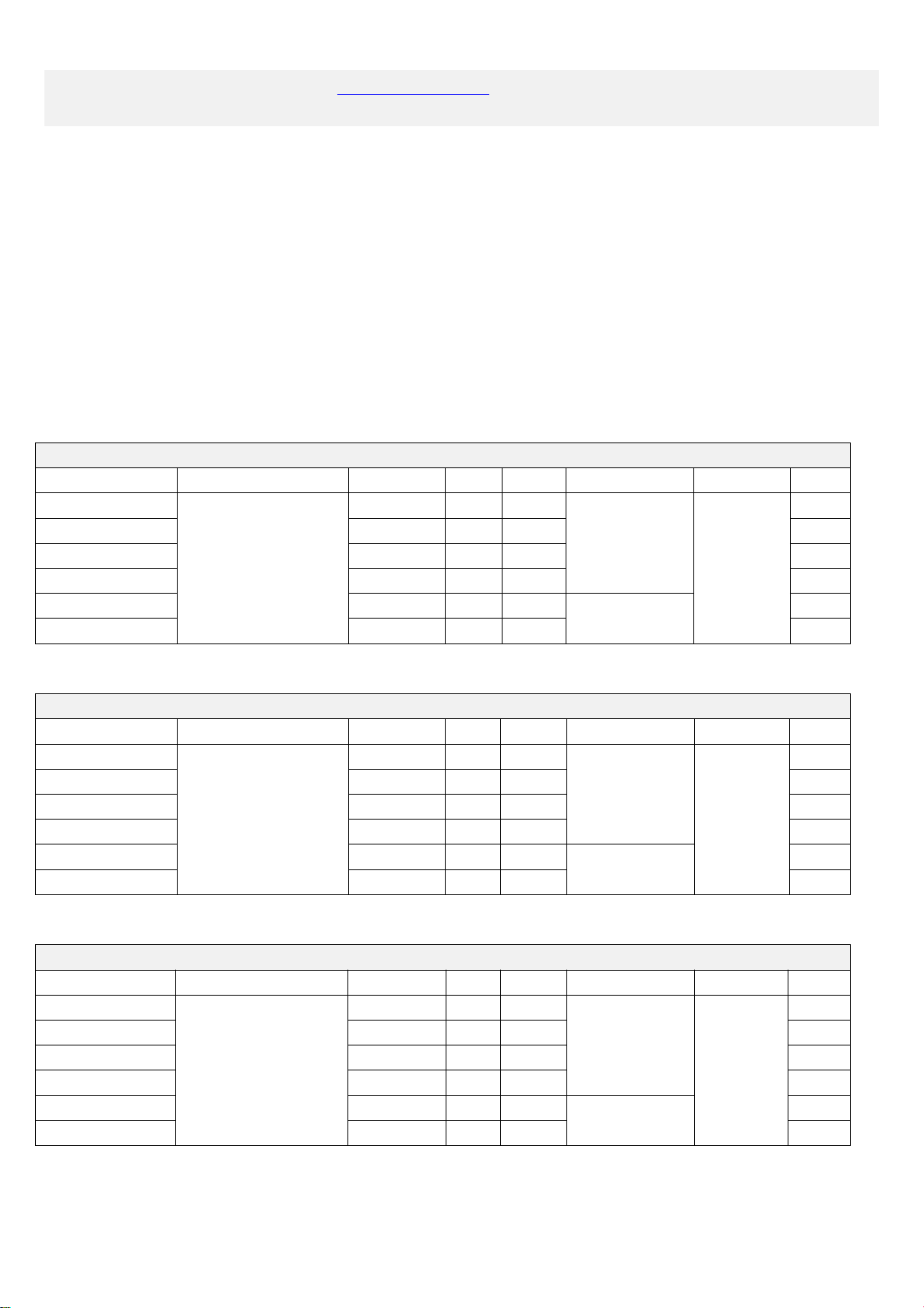
I3HGP Motherboard Series
Motherboard Model
Optional Intel Core CPU
LAN(RJ45)
COM
USB
Memory(MAX)
DC Power
GPIO
I3HGP-2C
I3-3217U
I3-3227U
1
2
8
8GB
+12V
0
I3HGP-6C
1
6
8
1
I3HGP-2L2C
2
2
6
0
I3HGP-2L6C
2
6
6
1
I3HGP-2C-2G
1
2
8
10GB
0
I3HGP-6C-2G
1
6
8
1
I5HGP Motherboard Series
Motherboard Model
Optional Intel Core CPU
LAN(RJ45)
COM
USB
Memory(MAX)
DC Power
GPIO
I5HGP-2C
I5-3317U
I5-3337U
I5-3437U
1
2
8
8GB
+12V
0
I5HGP-6C
1
6
8
1
I5HGP-2L2C
2
2
6
0
I5HGP-2L6C
2
6
6
1
I5HGP-2C-2G
1
2
8
10GB
0
I5HGP-6C-2G
1
6
8
1
I7HGP Motherboard Series
Motherboard Model
Optional Intel Core CPU
LAN(RJ45)
COM
USB
Memory(MAX)
DC Power
GPIO
I7HGP-2C
I7-3517U
I7-3537U
1
2
8
8GB
+12V
0
I7HGP-6C
1
6
8
1
I7HGP-2L2C
2
2
6
0
I7HGP-2L6C
2
6
6
1
I7HGP-2C-2G
1
2
8
10GB
0
I7HGP-6C-2G
1
6
8
1

- 2 -
The I3HGP, I5HGP, I7HGP motherboards support Intel processors(FCBGA1023 socket):
Motherboard
Model
Processor
Model
Intel
Brand
Cores
Processor Base
Frequency (GHz)
Max. Turbo
Frequency (GHz)
TDP
(W)
CPU Graphics
I3HGP
I3-3217U
Core I3
2
1.8
/
17
Integrated Intel HD Graphics
4000 in CPU.
(1080P,2K resolution,FHD)
I3-3227U
1.9
/
I5HGP
I5-3317U
Core i5
1.7
2.6
I5-3337U
1.8
2.7
I5-3437U
1.9
2.9
I7HGP
I7-3517U
Core i7
1.9
3.0
I7-3537U
2.0
3.1
Notice:
1. Changing the number of network ports will only affect the number of USB2.0 and will not affect others.
2. By default, when the motherboard has single network port,it will only has 8*USB.
If you want to use 3G/4G or 2-in-1 Bluetooth WIFI module, the motherboard will only support 7*USB.
3. By default, when the motherboard has dual network ports,it will only has 6*USB.
If you want to use 3G/4G or 2-in-1 Bluetooth WIFI module, the motherboard will only support 5*USB.
Changes in the number of USB
LAN
USB
Use module(3G,4G,WIFI&Bluetooth,etc) or not
1
8
Not use
1
7
Use
2
6
Not use
2
5
Use
- 3 -
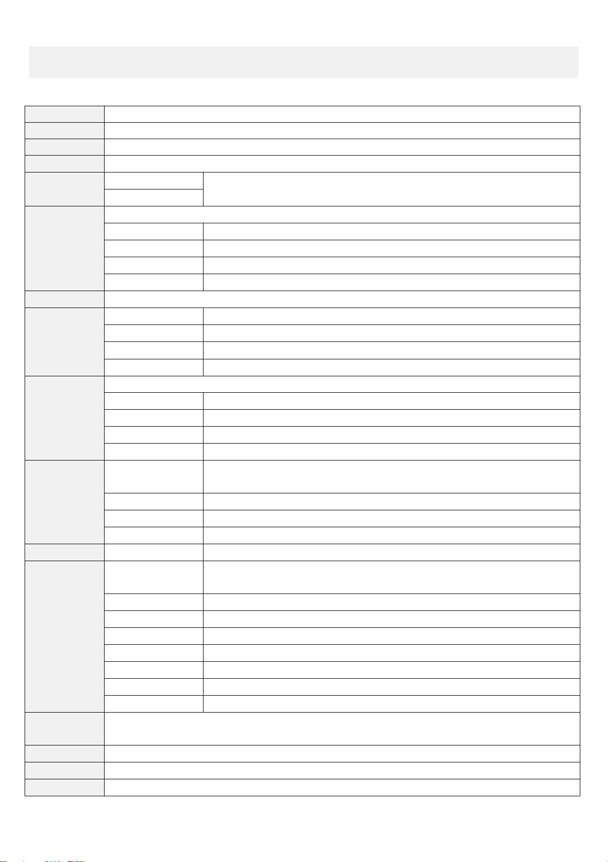
Chapter One The Motherboard Specifications
Form Factor
Standard Mini-ITX ,170*170*18mm(L*W*H)
Intel CPU
Support 3th generation Core I3/I5/I7 CPU: I3-3217U,I5-3317U,I7-3517U,etc.
Chipset
HM65/HM67/HM70/HM76 express Chipset.
Memory
1*DDR3 SODIMM 1333/1600MHz memory channel supports Max 8GB RAM.
Power Supply
1*DC_JACK
Support DC 12V ; Recommended to use 12V 5A or above.
The motherboard power consumption is about 30W.
1*DC_PWR
Display
Intel HD Graphics 4000 in CPU;Support single display, dual display copy, dual display expansion,single display under DOS.
1*VGA DB15 interface
Support Max resolution 1920*1200@60HZ
1*HDMI 1.4 interface
Support Max resolution 1920*1080@60HZ (1080P,2K resolution,FHD)
1*LVDS pin
Support Max resolution 1920*1080@60HZ(1080P,2K resolution,FHD) (2*15Pin,2.0mm)
1*VGA_OUT pin
Support Max resolution 1920*1200@60HZ (1*12Pin,2.0mm)
Ethernet
1* Realtek8111E Gigabit NIC chip supports Wake-on-LAN,PXE function. Other options: dual Ethernet ports.
Hard Disk
1*SATA1 interface
Standard SATA3.0 hard disk interface,Max transmission speed 6.0Gbps.
1*SATA2 interface
Standard SATA2.0 hard disk interface,Max transmission speed 3.0Gbps.
1*MSATA interface
Support MSATA hard disk.
2*SATA_PWR pins
Can take 5V ,12V from hard disk power supply pin. (1*4Pin,2.54mm)
Sound
Integrated Realtek ALC662 HD digital audio decoder,6-channel high-fidelity audio controller.
1*FRONT_SPK port
Support audio output (Green color)
1*MIC_IN interface
Support microphone input (Pink color)
1*JAMP pin
The amplifier supports 8Ω5W speaker and two channels of output. (1*4Pin,2.0mm)
1*F_AUDIO pin
Standard audio pin (2*5Pin,2.54mm)
USB
2*USB3.0 interfaces
Rear standard USB3.0 interfaces; Notice:When the motherboard uses the HM65/HM67 chipset,
the speed of the two USB3.0 ports becomes the speed of USB2.0
2*USB2.0 interfaces
Rear standard USB2.0 interfaces.
1*FUSB1 pin
Front USB2.0 pin,one group has 2*USB2.0 pins. (2*5Pin,2.54mm)
1*FUSB2 pin
Front USB2.0 pin,one group has 2*USB2.0 pins. (2*5Pin,2.54mm)
Switch
1*F_PANEL pin
Switch, power supply light, hard disk light, restart pin. (2*5Pin , 2.54mm)
Other I/O
COM pins
They are serial ports.The motherboard has 2*COM or 6*COM pins to choose;
The COM pins support standard RS232 signal.
1*LPT pin
It is parallel port. The motherboard has standard LPT pin for printer. (2*13,2.54mm)
1*MINI_PCIE interface
Support WIFI/3G/4G module.
1*SIM card slot
Support SIM card. A SIM card is required when using 3G/4G function.
1*CLR_CMOS pin
Motherboard clears,discharges pin. (1*2Pin,2.54mm)
1*BAT socket
Battery socket (1*2Pin,2.0mm)
1*FAN1 pin
Fan pin (1*3Pin,2.54mm)
1*FAN2 pin
Fan pin (1*3Pin,2.54mm)
Operating
Environment
Operating temperature:-20℃~60℃;
Working humidity:5%~95% Relative humidity, no condensation.
BIOS
AMI BIOS supports power on,timing switch,remote switch,intelligently identify devices.
Watch Dog
Watchdog programming supports hardware reset function (256 levels, 0~255 seconds).
Operating System
Support Windows 10,Windows 8.1,Windows 7,Windows XP,Ubuntu 14.04,Ubuntu 16.04,etc.
- 4 -
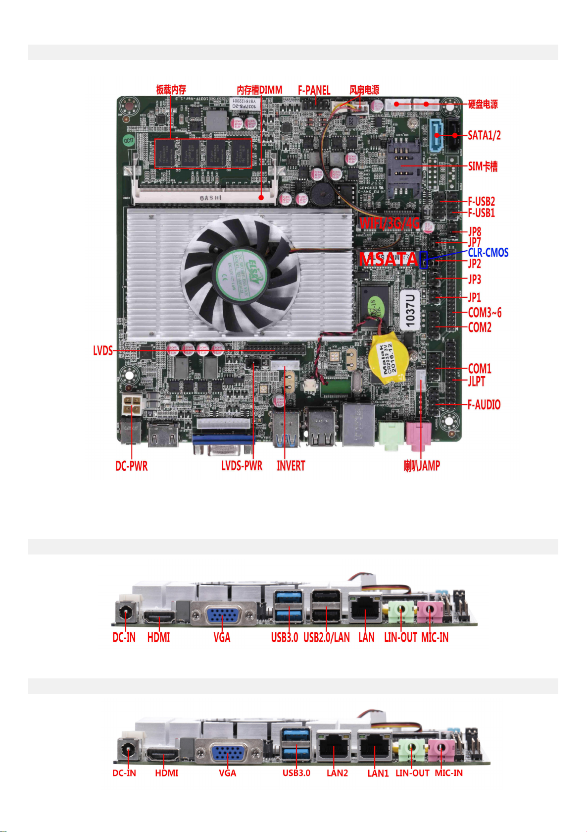
1.1 The motherboard pictures:
1*LAN:
2*LAN:

- 5 -
1.2 Motherboard drawing:
- 6 -
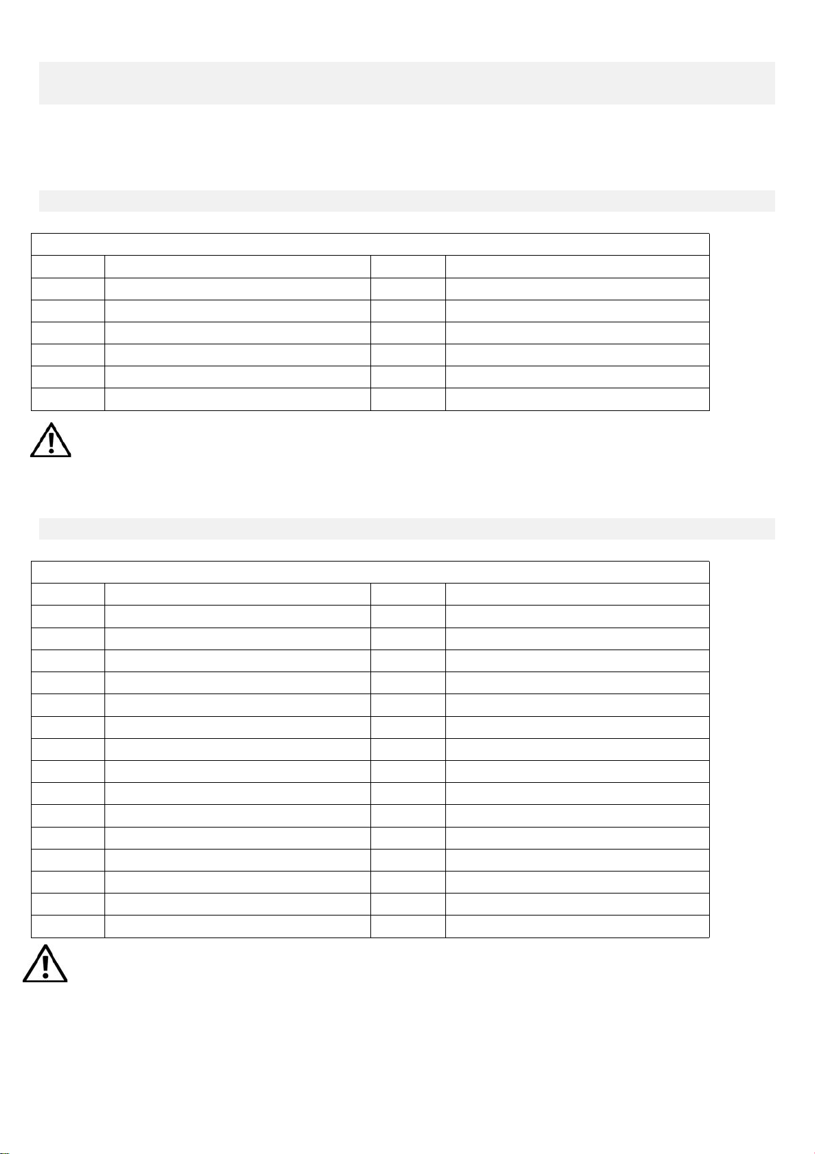
Chapter two The Motherboard pin definition and description
2.0 Display output interface and pin definition:
2.1 VGA pin definition:
Position symbol:VGA_H (1*12Pin,2.0mm)
pin
definition
pin
definition
1
GND
2
VSYNC
3
HSYNC
4
GND
5
RED
6
GND
7
GRN
8
GND
9
BLUE
10
GND
11
DDC_DATA
12
DDC_CLK
Note: The VGA_H pin signal is the same signal as the rear VGA interface.Only support dual display copy function.
When using the dual display copy function, the display brightness will decrease.
2.2 LVDS pin definition:
Position symbol:LVDS (2*15Pin,2.0mm)
pin
definition
pin
definition
1
VCC
2
VCC
3
VCC
4
GND
5
GND
6
GND
7
ADO0-
8
ADO0+
9
ADO1-
10
ADO1+
11
ADO2-
12
ADO2+
13
GND
14
GND
15
ACLK-
16
ACLK+
17
ADO3-
18
ADO3+
19
BDO0-
20
BDO0+
21
BDO1-
22
BDO1+
23
BDO2-
24
BDO2+
25
GND
26
GND
27
BCLK-
28
BCLK+
29
BDO3-
30
BDO3+
Note: When inserting the LVDS cable, the first stitch of the LVDS cable must correspond to the first pin of the
motherboard pin. If the plug is reversed or inserted incorrectly, there is a danger of burning the screen and burning the
motherboard!

- 7 -
2.2.1 Backlight power supply definition:
Position symbol:INVERT (1*6Pin,2.0mm)
pin
definition
1
+12V
2
+12V
3
ON/OFF (Backlight switch)
4
ADJ (Backlight brightness adjustment)
5
GND
6
GND
2.2.2 Screen operating voltage:
Position symbol:LVDS_PWR (2*3Pin,2.54mm)
pin
definition
1-3 short circuit
+5V
3-5 short circuit
+3.3V
3-4 short circuit
+12V
Note: Screens of different sizes require different operating voltages. The motherboard provides three screen
operating voltages of 3.3V, 5V and 12V. Please set the corresponding value of LVDS_PWR according to the working
voltage required by the screen, otherwise there will be danger of burning the screen and burning the motherboard!
2.3 Serial port(COM) function and pin definition:
The 2*COM,6*COM pins support standard RS232 signal.
The 9th pin of COM1/COM2 can change the jumper setting to output +5V or +12V voltage by JP1/JP3.
Position symbol:JP1 (2*3Pin,2.54mm)
pin
The 9th pin of COM1 is charged
1-2 short circuit
+5V
3-4 short circuit
+12V
5-6 short circuit
Without electricity
COM1/COM2 pin definition:
Position symbol:COM1/2 (2*5Pin,2.54mm)
pin
definition
pin
definition
1
DCD
2
RXD
3
TXD
4
DTR
5
GND
6
DSR
7
RTS
8
CTS
9
RI
10
NC
Position symbol:JP3 (2*3Pin,2.54mm)
pin
The 9th pin of COM2 is charged
1-2 short circuit
+5V
3-4 short circuit
+12V
5-6 short circuit
Without electricity
5●3●1■
4●
- 8 -
COM3~COM6 pins definition:
Position symbol:COM3~6 (2*20Pin,2.0mm)
pin
definition
pin
definition
1
COM3_DCD
2
COM3_RXD
3
COM3_TXD
4
COM3_DTR
5
GND
6
COM3_DSR
7
COM3_RTS
8
COM3_CTS
9
COM3-RI
10
NC
11
COM4_DCD
12
COM4_RXD
13
COM4_TXD
14
COM4_DTR
15
GND
16
COM4_DSR
17
COM4_RTS
18
COM4_CTS
19
COM4-RI
20
NC
21
COM5_DCD
22
COM5_RXD
23
COM5_TXD
24
COM5_DTR
25
GND
26
COM5_DSR
27
COM5_RTS
28
COM5_CTS
29
COM5-RI
30
NC
31
COM6_DCD
32
COM6_RXD
33
COM6_TXD
34
COM6_DTR
35
GND
36
COM6_DSR
37
COM6_RTS
38
COM6_CTS
39
COM6-RI
40
NC
2.4 Parallel port(LPT) pin definition:
Position symbol:JLPT (2*13Pin,2.0mm)
pin
definition
pin
definition
1
STB
2
AFD
3
PD0
4
ERR
5
PD1
6
INIT
7
PD2
8
SLIN
9
PD3
10
GND
11
PD4
12
GND
13
PD5
14
GND
15
PD6
16
GND
17
PD7
18
GND
19
ACK
20
GND
21
BUSY
22
GND
23
PE
24
GND
25
SLCT
26
NC
- 9 -
2.5 USB pin definition:
Position symbol:F_USB1/2 (2*5Pin,2.54mm)
pin
definition
pin
definition
1
VCC+5V
2
VCC+5V
3
DATA0-
4
DATA1-
5
DATA0+
6
DATA1+
7
GND
8
GND
9
NC
10
GND
2.6 Audio interface and pin definition:
Position symbol:F_AUDIO (2*5Pin,2.54mm)
pin
definition
pin
definition
1
MIC-L
2
GND
3
MIC-R
4
NC
5
LINE OUT-R
6
RET_R
7
SENSE
8
NC
9
LINE OUT-L
10
RET_L
2.7 Speaker(Power Amplifier) pin definition:
Position symbol:JAMP (1*4Pin,2.0mm)
pin
definition
1
L+
2
L-
3
R-
4
R+
2.8 GPIO pin definition:
Position symbol:J_GPIO (2*5Pin,2.0mm)
pin
definition
pin
definition
1
GPIO_IN0
2
GPIO_OUT0
3
GPIO_IN1
4
GPIO_OUT1
5
GPIO_IN2
6
GPIO_OUT2
7
GPIO_IN3
8
GPIO_OUT3
9
+5V
10
GND
11
+3.3V
12
GND

- 10 -
2.9 Power supply and switch pin definition:
The motherboard provides a standard 5.5*2.5mm DC header (DC_JACK),1*4Pin ATX power supply interface.
4Pin ATX power supply port definition:
Position symbol:DC_PWR (2*2Pin)
pin
definition
1
GND
2
GND
3
+12V
4
+12V
Switch pin definition:
Position symbol:F_PANEL (2*5Pin,2.54mm)
pin
definition
pin
definition
1
HDLED+
Hard disk indicator light
2
PWRLED+
Power indicator light
3
HDLED-
4
GND
5
GND
Reset button
6
GND
Power switch control
7
RST
8
P_SW IN
9
GND
10
NC
(1) Hard disk indicator light:
The 1st and 3rd pins are HDDLED. The 1st pin is the positive side of the LED.When the hard disk is being read
or written, the indicator light will flash, indicating that the hard disk is running.
(2)Power indicator light:
The 2nd and 4th pins are Power LED. The 2nd pin is the positive side of the LED.When the motherboard is
powered on, the power indicator light is on.When the motherboard is powered off, the power indicator light
is off.
(3)Reset button:
The 5th,7th pins are Reset Button.When the system fails and cannot continue to work, the reset can restart
the system.
(4)Power switch control:
The 6th, 8th pins are Power Button.Use these two pins to connect to the bounce switch on the front panel of
the chassis to turn on or off the computer.

- 11 -
2.10 hard disk interface and definition:
The motherboard has:
1*SATA3.0 hard disk interface;
1*SATA2.0 hard disk interface;
2*4Pin hard disk power supply voltage interface;
1*MSATA interface;
The SATA1 supports Max transmission speed 6.0Gbps.
The SATA2 supports Max transmission speed 3.0Gbps.
SATA1/2 definition: SATA_PWR definition:
Position symbol:SATA1/2
pin
definition
1
GND
2
SATA_TXP
3
SATA_TXN
4
GND
5
SATA_RXN
6
SATA_RXP
7
GND
Note:
The first pin of the SATA_PWR hard disk power supply interface is 12V output, and the fourth pin is 5V output. When
using, you must use the customized power cord from our company,to avoid burning the hard disk.
2.11 Fan interface definition:
Position symbol:FAN1/2 (1*3Pin,2.54mm)
pin
definition
1
GND
2
+12V
3
TAC(Fan speed detection)
2.12 Motherboard discharge clear and battery:
CMOS is powered by the button battery on the motherboard.
Clearing CMOS will cause the previous BIOS settings to be cleared and set to the original factory setting.
Position symbol:SATA_PWR1/2 (1*4Pin,2.0mm)
pin
definition
1
12V
2
GND
3
GND
4
5V

- 12 -
Clearing CMOS procedures:
(1)Turn off the motherboard and disconnect the power.
(2)Using metal conductors to briefly connect the pin 2,pin 3 of CLR_CMOS for 5~6 seconds.
(3)When booting up, press "Delete" to enter the BIOS.
(4)After entering the BIOS, press "F9" ,"Enter" to reload the optimal default value.
(5)Press the "F10" to save and exit the setting.
CMOS pin definition:
Position symbol:CLR_CMOS (1*3Pin,2.0mm)
pin
Function
1-2 short circuit
Normal start
2-3 short circuit
Clear CMOS content,BIOS will restore factory settings.
Note:
Please do not clear the CMOS when the motherboard is powered on or is charged, so as not to damage the motherboard.
Button battery pin definition:
Position symbol:BAT (1*2Pin)
pin
definition
1
positive electrode
2
negative electrode
Button battery specification: 3V CR2032
Note:
(1)Please make sure the battery is facing up.
(2)Please make sure the battery voltage is enough 2.8V~3V.
(3)Please must use the same model or the manufacturer recommend the same type of battery.
(4)If the battery is not replaced correctly, there is a danger of explosion!

- 13 -
Chapter three BIOS Setup
3.0 How to enter the BIOS?
Method 1: After booting, press“Delete”continuously to enter the BIOS directly.
Method 2: Press“F11”continuously after booting, then select“Enter Setup”to enter the BIOS.
3.1 Main Menu(BIOS information and date and time):
(1)BIOS Vendor: American Megatrends
(2)Core Version:
(3)Build Date and Time: 06/13/2018
(4)CPU Information:
(5)Memory Information:
(6)System Date: The format is week Month/day/year
(7)System Time: The format is hour/minute/second
BIOS hot key
Function
When startup, press the “Delete”button
Enter “BIOS”
When startup, press the “F11”button
Select“Setup”,or select enter“BIOS”.
← →
Select Screen(Move the left and right arrows to select an entry).
↑ ↓
Select Item(Move the up and down arrows to select an entry).
Enter
Select(Select item and enter the submenu).
+/-
Change Opt.(Change selections,add or subtract values).
F1
General help(Show related help content).
F9
Optimized Defaults(Go back to the vendor's default settings).
F10
Save&Exit
Esc
Exit

- 14 -
3.2 Advanced (Advanced Menu Setting):
(1)
(1)ACPI Settings: Advanced configuration and power management interface setting.
(2)Trusted Computing: Trusted computing module.
(3)CPU Configuration: CPU parameter information and common setup options.
(4)SATA Configuration: Hard disk mode settings and hard disk information.
(5)Info Report Configuration:
(6)Intel (R) Rapid Start Technology:
(7)USB Configuration: USB information and control options.
(8)Super IO Configuration:
(9)CPU PPM Configuration: CPU power supply management configuration.

- 15 -
3.2.1 ACPI Settings:
(1)Enable ACPI Auto Configuration: This item is ACPI automatically configured.It can“Enabled”or“Disabled”
the ACPI auto configuration of the BIOS.
(2)Enable Hibernation: This item is hibernation support.It can“Enabled”or“Disabled”the system hibernation
function(OS/S4 sleep state).However, this option does not work on some operating systems.
(3)ACPI Sleep State:This item is used to select the power saving mode when the system sleeps.The mode is
different, the system power consumption will be different.
Suspend Disabled: Turn off sleep mode.
S1(CPU Stop Clock): The CPU stops working, but the other devices are still powered normally.
S3(Suspend to Ram): Suspend to memory.
(4)Lock Legacy Resources: It can“Enabled”or“Disabled”legacy resources lock.
(5)S3 Video Repost: When the S3/STR sleep mode is awakened,BIOS post function of the VGA is turned on as well.
(6)Wake system with Fixed Time: It is timed boot setting.The“Disabled”is turn off;The“Enabled”is turn on.
RTC Alarm Date(Days):
Wake up hour:
Wake up minute:
Wake up second:

- 16 -
3.2.3 CPU Configuration:
The read-only item contains the details of the CPU.
It specifically includes information such as CPU manufacturer,model,frequency,level 1 cache capacity,and level
2 cache capacity,etc.
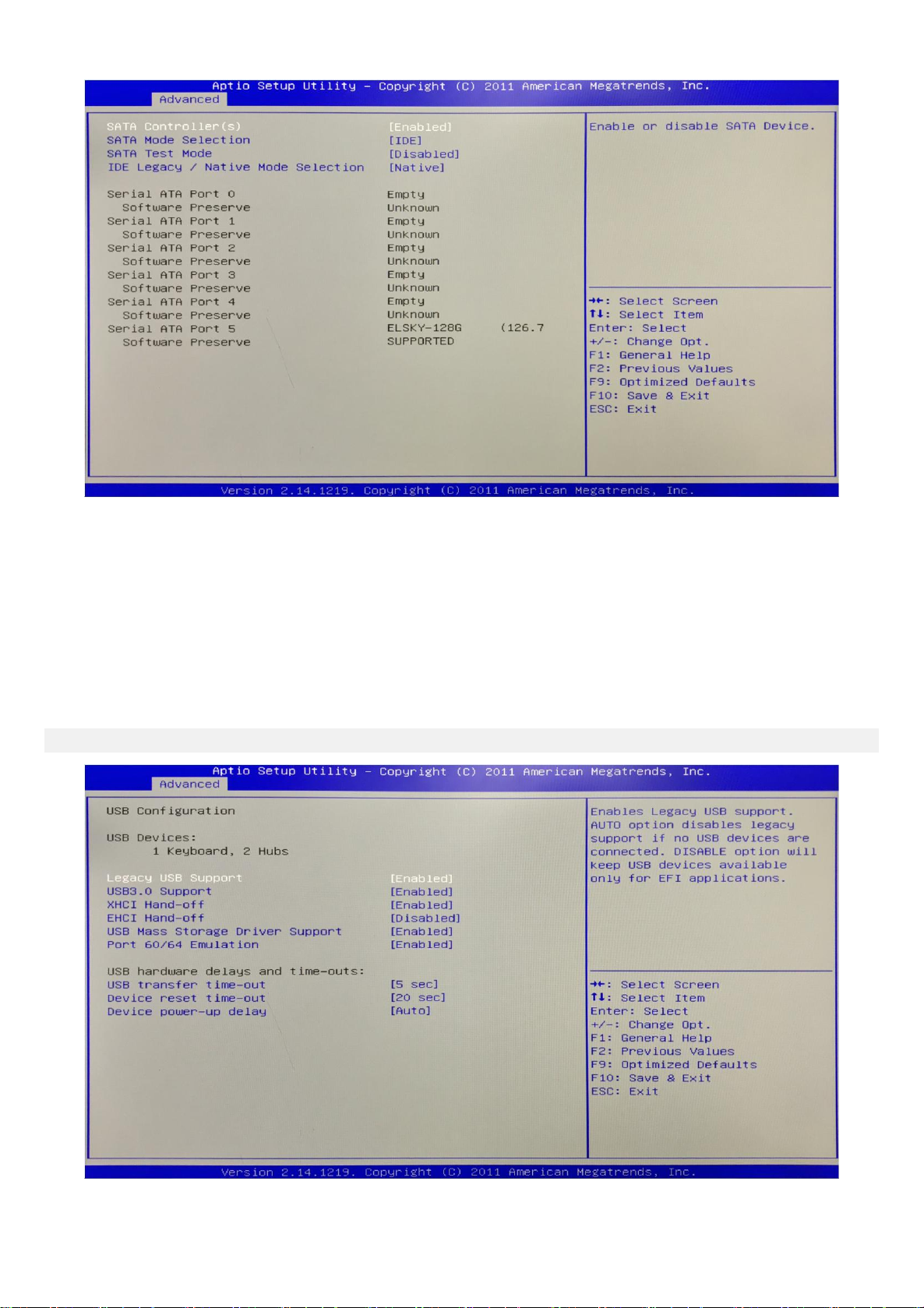
3.2.4 SATA Configuration(Hard disk configuration):
- 17 -
(1)SATA Controller:
(2)SATA Mode Selection: It is Hard disk mode setting.Its options are AHCI,IDE.
(3)SATA Test Mode: It is Hard disk test mode.
(4)IDE Legacy / Native Mode Selection:
3.2.5 USB Configuration:

- 18 -
(1)Legacy USB Support: This item is used for the settings of the old USB.
If you need to support USB device,U disk, USB keyboard under DOS,please set this item to “Enabled ”or
“Auto”,otherwise select“Disabled”.
(2)XHCI Hand-off: Whether to enable the USB XCHI transport protocol.
(3)EHCI Hand-off: This option is used to determine whether to cut the USB hub into USB2.0 mode before
entering the OS.
(4)USB Mass Storage Driver Support: This is a switch that supports USB mass storage devices.
(5)USB Transfer time-out: Set the time-out of the control, batch, and interrupt transmission. By default, the
time is set to“5 sec”.
(6) Device reset time-out: Set the time-out of the large-capacity USB disk boot command. By default, the time
is set to“20 sec”.
(7) Device Power-up Delay: Set the maximum delay time that the USB device reports to the primary
controller.

- 19 -
3.2.6 Super IO Configuration:
It contains COM pin (Serial port),LPT port(Parallel port) configuration information and settings.
(1)COM 1 Configuration:
(2)COM 2 Configuration:
(3)COM 3 Configuration:
(4)COM 4 Configuration:
(5)COM 5 Configuration:
(6)COM 6 Configuration:
(7)LPT Port Configuration:
(8)Restore AC Power Loss By IO: It is the power on,power off switch in BIOS.
Power Off: After the motherboard is powered,it won't automatically boot and you need to boot it
manually.
Power On: After the motherboard is powered,it will automatically boot and you don't need to boot it
manually.

- 20 -
3.3 Chipset Setting:
PCH Configuration: It is South Bridge Configuration. It includes PCI-E,USB,PXE options.
NB Configuration: It is North Bridge Configuration.It includes video memory,display device options.
3.3.1 PCH Configuration(South Bridge Configuration):
Other manuals for I3HGP
1
This manual suits for next models
27
Table of contents
Other ELSKY Motherboard manuals


