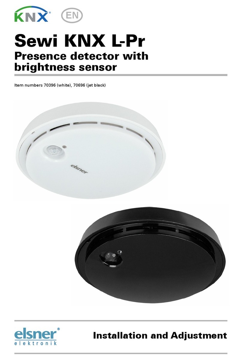
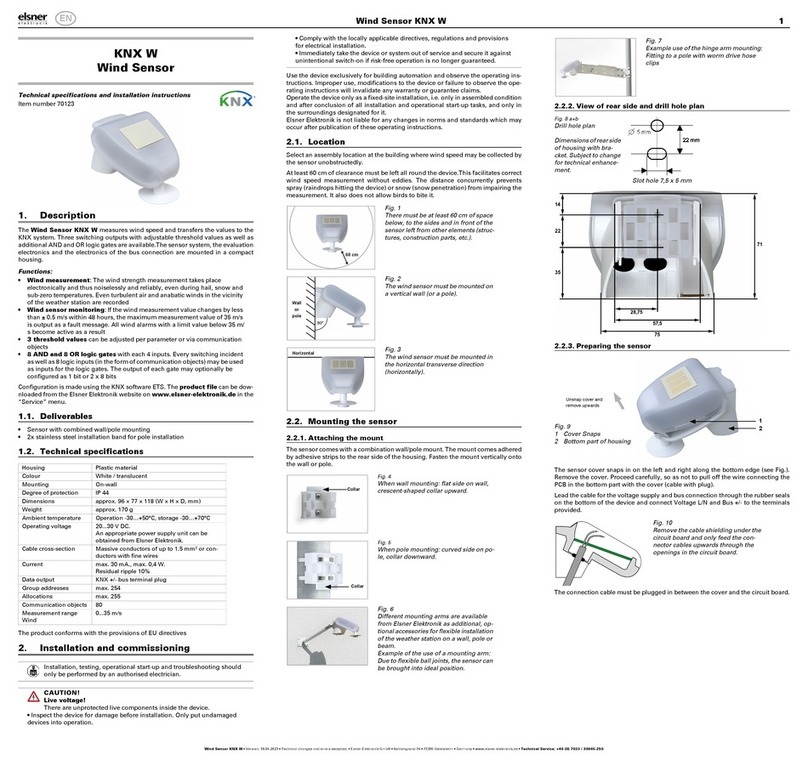
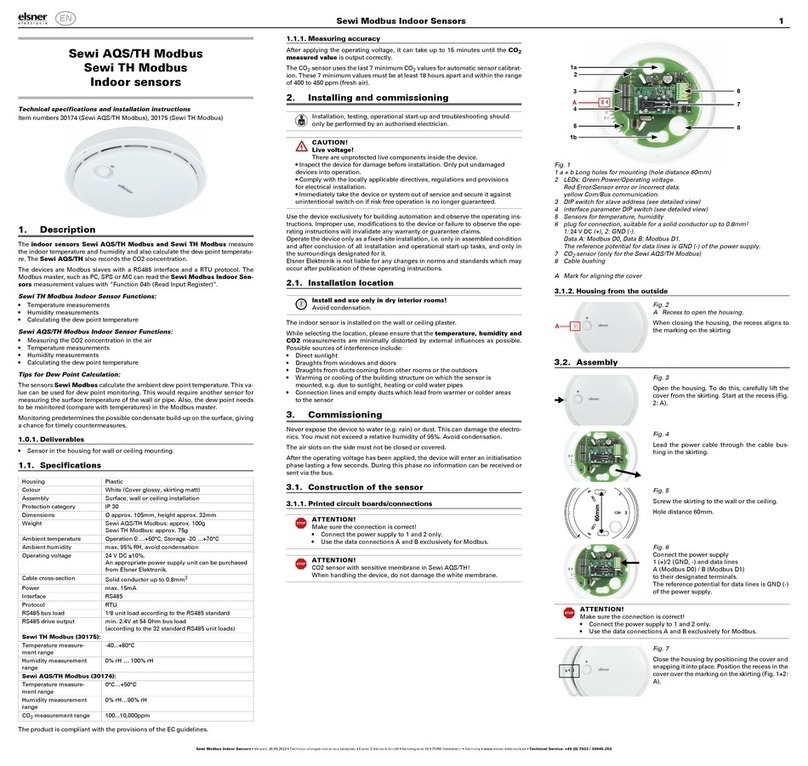
elsner elektronik Intra-Sewi KNX L-Pr Guide

Intra-Sewi KNX L-Pr and
Intra-Sewi KNX TH-L-Pr
Brightness and Presence Detectors
Item numbers
70670 Intra-Sewi KNX L-Pr, white
70672 Intra-Sewi KNX L-Pr, black
70680 Intra-Sewi KNX TH-L-Pr, white
70682 Intra-Sewi KNX TH-L-Pr, black
EN
Installation and Adjustment


1 Contents
Elsner Elektronik GmbH • Sohlengrund 16 • 75395 Ostelsheim • Germany
Sensors Intra-Sewi KNX TH-L-Pr and Intra-Sewi KNX L-Pr
Version: 30.08.2018 • Technical changes and errors excepted.
1. Description ........................................................................................... 7
1.0.1. Scope of delivery .......................................................................................... 7
1.0.2. *Measuring accuracy .................................................................................... 9
2. Installation and start-up ....................................................................... 9
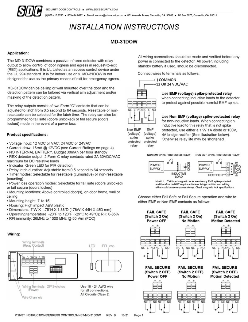
2.0.1. Coverage area of the motion detector ...................................................... 10
2.0.2. Installation in false ceiling .......................................................................... 11
2.0.3. Installation in connector socket ................................................................. 12
2.0.4. Back view: connection ................................................................................ 13
2.0.5. Front view: programming and addressing ............................................... 14
3. Maintenance ....................................................................................... 14
4. Transfer protocol ............................................................................... 15
5. Parameter setting .............................................................................. 27
5.0.1. Threshold value 1/2/3/4 .............................................................................. 28
5.0.1.1. Threshold value ............................................................................ 28
5.0.1.2. Switching output .......................................................................... 29
5.0.1.3. Block .............................................................................................. 30
5.0.2. Master 1/2/3/4 .............................................................................................. 34
5.0.3. Align communication between master and slave .................................... 37
5.0.3.1. Sending cycle slave - switch-off delay master ........................... 37
5.0.3.2. Slave cycle reset ........................................................................... 37
5.0.4. Threshold value 1, 2, 3, 4 ........................................................................... 39
5.0.4.1. Threshold value ............................................................................ 39
5.0.4.2. Switching output .......................................................................... 40
5.0.4.3. Block .............................................................................................. 41
5.0.4.4. General control ............................................................................. 41
5.0.4.5. General setpoint values ............................................................... 43
5.0.4.6. Comfort Setpoint .......................................................................... 44
5.0.4.7. Standby setpoint ........................................................................... 45
5.0.4.8. Eco setpoint ................................................................................... 45
5.0.4.9. Setpoint values for frost/heat protection (building protection) 46
5.0.4.10.General control variables ............................................................. 46
5.0.5. Heating control level 1/2 ............................................................................. 47
5.0.6. Cooling control level 1/2 ............................................................................. 49
5.0.7. Threshold value 1, 2, 3, 4 ........................................................................... 52
5.0.7.1. Threshold value ............................................................................ 52
5.0.7.2. Switching output .......................................................................... 53
5.0.7.3. Block .............................................................................................. 54
5.0.7.4. General control ............................................................................. 55
5.0.7.5. Controller setpoint ........................................................................ 55
5.0.7.6. Dehumidification and/or humidification ..................................... 56
5.0.8. Cooling medium temp. monitoring ........................................................... 58
5.0.8.1. Threshold value ............................................................................ 58

3 Contents
Elsner Elektronik GmbH • Sohlengrund 16 • 75395 Ostelsheim • Germany
Sensors Intra-Sewi KNX TH-L-Pr and Intra-Sewi KNX L-Pr
Version: 30.08.2018 • Technical changes and errors excepted.
5.0.8.2. Switching output .......................................................................... 59
5.0.8.3. Blocking ......................................................................................... 59
5.0.9. Control variable comparator 1/2 ................................................................ 62
5.0.9.1. AND logic ....................................................................................... 62
5.0.9.2. OR logic ......................................................................................... 63
5.0.10. AND logic 1-4 and OR logic outputs 1-4 ................................................... 63
5.0.10.1.Block .............................................................................................. 64
5.0.10.2.Monitoring ..................................................................................... 64
5.0.11. Connection inputs of the OR logic ............................................................. 67

5 Clarification of signs
This manual is amended periodically and will be brought into line with new software
releases. The change status (software version and date) can be found in the contents footer.
If you have a device with a later software version, please check
www.elsner-elektronik.de in the menu area "Service" to find out whether a more up-to-
date version of the manual is available.
Clarification of signs used in this manual
Installation, inspection, commissioning and troubleshooting of the device
must only be carried out by a competent electrician.
Safety advice.
Safety advice for working on electrical connections, components,
etc.
DANGER! ... indicates an immediately hazardous situation which will lead to
death or severe injuries if it is not avoided.
WARNING! ... indicates a potentially hazardous situation which may lead to
death or severe injuries if it is not avoided.
CAUTION! ... indicates a potentially hazardous situation which may lead to
trivial or minor injuries if it is not avoided.
ATTENTION! ... indicates a situation which may lead to damage to property if it is
not avoided.
ETS In the ETS tables, the parameter default settings are marked by
underlining.

6 Clarification of signs

7 Description
Sensors Intra-Sewi KNX TH-L-Pr and Intra-Sewi KNX L-Pr • Version: 30.08.2018 • Technical changes and errors excepted.
1. Description
The Sensor Intra-Sewi KNX L-Pr for the KNX building bus system captures bright-
ness and motion in rooms.
The Sensor Intra-Sewi KNX TH-L-Pr additionally measures the temperature and the
air humidity and calculates the dew-point. Via the bus, the indoor sensor can receive
external values of temperature and humidity and process them further with its own
data to a total value (mixed value, e.g. room average). Integrated PI-controllers control
ventilation (humidification/dehumidification according to humidity) and heating/cool-
ing (according to temperature).
The Sensor Intra-Sewi KNX TH-L-Pr can output a warning to the bus as soon as the
comfort field, as per DIN 1946, is left. Actuating variable comparators can compare and
output variables that were received via communication objects.
All measurement values can be used for the control of limit-dependent switching out-
puts. States can be linked via AND logic gates and OR logic gates.
Functions:
•Brightness measurement with brightness control
• Motion detection
•Threshold values can be adjusted per parameter or via communication
objects
•4 AND and 4 OR logic gates, each with 4 inputs. All switching events as well
as 16 logic inputs (in the form of communications objects) can be used as
inputs for the logic gates. The output of each gate can be configured optionally
as 1-bit or 2 x 8-bit
Additional functions Intra-Sewi KNX TH-L-Pr:
• Measuring the temperature and air humidity (relative, absolute), each with
mixed value calculation. The share of internal measurement value and
external value can be set as a percentage
• Bus message, whether the values for temperature and air humidity are within
the comfort field (DIN 1946). Dew point calculation
•PI-controller for heating (one or two-stage) and cooling (one or two-stage)
according to temperature. Regulation according to separate setpoints or basic
setpoint temperature
•PI controller for humidity according to humidity: Ventilate/Air (one-stage) or
Ventilate (one or two-stage)
•2 actuation variable comparators to output minimum, maximum or
average values. 5 inputs each for values received via communication objects
Configuration is made using the KNX software ETS. The product file can be down-
loaded from the Elsner Elektronik website on www.elsner-elektronik.de in the “Ser-
vice” menu.
1.0.1. Scope of delivery
•Sensor

8 Description
Sensors Intra-Sewi KNX TH-L-Pr and Intra-Sewi KNX L-Pr • Version: 30.08.2018 • Technical changes and errors excepted.
• Pre-assembled clamps for false ceiling installation
• Support ring for connector socket installation
For socket installation you will need in addition (not supplied):
• Socket Ø 60 mm, 42 mm deep
1.1. Technical data
Housing Plastic, glass
Colour • similar to signal white RAL 9003
• similar to jet black RAL 9005
Assembly built-in, in false ceiling or connector socket
Protection category IP 30
Dimensions Ø approx. 80 mm;
height above wall approx. 5 mm
height in wall (installation) approx. 31 mm (incl. clamps)
Total weight approx. 50 g
Ambient temperature Operation -20…+60°C, storage -20…+70°C
Ambient humidity max. 95% RH, avoid condensation
Operating voltage KNX bus voltage
Bus current max. 10 mA
Data output KNX +/- bus plug-in terminal
BCU type Integrated microcontroller
PEI type 0
Group addresses max. 254
Assignments max. 254
Communication objects Intra-Sewi KNX TH-L-Pr: 252
Intra-Sewi KNX L-Pr: 122
Brightness sensor:
Measurement range 0 lux … 2,000 lux (higher values can be measured an dis-
played)
Resolution 1 lux at 0…2,000 lux
Accuracy ±15% of the measurement value at 30 lux … 2,000 lux
Motion sensor:
Coverage angle approx. 94° × 82° (see also Coverage area of the motion
detector)
Range approx. 5 m
Temperature sensor (only Intra-Sewi KNX TH-L-Pr):
Measurement range -20°C … +60°C
Resolution 0.1°C
Accuracy* ±0.7°C at -20°C...-10°C
±0.5°C at -10°C...+60°C
Humidity sensor (only Intra-Sewi KNX TH-L-Pr):
Measurement range 0% rH … 100% rH

9 Installation and start-up
Sensors Intra-Sewi KNX TH-L-Pr and Intra-Sewi KNX L-Pr • Version: 30.08.2018 • Technical changes and errors excepted.
The product is compliant with the provisions of the EU guidelines.
1.1.1. *Measuring accuracy
Deviations in measured values due to interfering sources (see chapter installation lo-
cation) must be corrected in the ETS in order to achieve the specified accuracy of the
sensor (offset).
During the Temperature measurement, the self-heating of the device is taken into
consideration by the electronics. It is compensated by the software, therefore the dis-
played/output indoor temperature measuring value is correct.
2. Installation and start-up
2.1. Installation notes
Installation, testing, operational start-up and troubleshooting should
only be performed by an electrician.
CAUTION!
Live voltage!
There are unprotected live components inside the device.
• National legal regulations are to be followed.
• Ensure that all lines to be assembled are free of voltage and take
precautions against accidental switching on.
• Do not use the device if it is damaged.
• Take the device or system out of service and secure it against
unintentional use, if it can be assumed, that risk-free operation is no
longer guaranteed.
The device is only to be used for its intended purpose. Any improper modification or
failure to follow the operating instructions voids any and all warranty and guarantee
claims.
After unpacking the device, check it immediately for possible mechanical damage. If it
has been damaged in transport, inform the supplier immediately.
The device may only be used as a fixed-site installation; that means only when assem-
bled and after conclusion of all installation and operational start-up tasks and only in
the surroundings designated for it.
Resolution 0.1% rH
Accuracy ± 7,5% rH at 0% … 10% rH
± 4,5% rH at 10% … 90% rH
± 7,5% rH at 90% … 100% rH

10 Installation and start-up
Sensors Intra-Sewi KNX TH-L-Pr and Intra-Sewi KNX L-Pr • Version: 30.08.2018 • Technical changes and errors excepted.
Elsner Elektronik is not liable for any changes in norms and standards which may occur
after publication of these operating instructions.
2.2. Installation location
Install and use only in dry interior rooms! Avoid condensation.
The Sensor is installed in a false ceiling or a standard connection socket (Ø 60 mm, 42
mm deep).
The device must be installed on the ceiling, so that the movement capturing takes
place from above. Make sure that the desired area is covered by the sensor's coverage
angle and that no obstacles obstruct the recording.
When selecting an installation location for Intra-Sewi KNX TH-L-Pr, please ensure
that the measurement results of temperature and humidity are affected as little as
possible by external influences. Possible sources of interference include:
• Direct sunlight
• Drafts from windows and doors
• Draughts from ducts coming from other rooms or the outdoors
• Warming or cooling of the building structure on which the sensor is mounted,
e.g. due to sunlight, heating or cold water pipes
• Connection lines and empty ducts which lead from warmer or colder areas to
the sensor
Measurement variations from such sources of interference must be corrected in the
ETS in order to ensure the specified accuracy of the sensor (offset).
2.2.1. Coverage area of the motion detector
Angle of coverage: approx. 94° × 82°
Range: approx. 5 m

11 Installation and start-up
Sensors Intra-Sewi KNX TH-L-Pr and Intra-Sewi KNX L-Pr • Version: 30.08.2018 • Technical changes and errors excepted.
Segmentation of the coverage area
Size of the coverage area
2.3. Installation of the sensor
2.3.1. Installation in false ceiling
Connect the bus line to the KNX terminal (red/black).
Place the device in the installation opening in the ceiling. For this, fold the clamps up-
wards and guide the device through the installation opening with the clamps first.
The device is automatically fixed by the clamps.
Distance Length Width
2.50 m approx. 5.40 m approx. 4.30 m
3.50 m approx. 7.50 m approx. 6.10 m
Fig. 1
width
length
Orientation of the sup-
port ring for socket ins-
tallation

12 Installation and start-up
Sensors Intra-Sewi KNX TH-L-Pr and Intra-Sewi KNX L-Pr • Version: 30.08.2018 • Technical changes and errors excepted.
2.3.2. Installation in connector socket
Before socket installation, remove the clamps for the false ceiling installation.
Screw the support ring onto the socket. Pay attention to the orientation as shown in the
chapter Coverage area of the motion detector.
Connect the bus line to the KNX terminal (red/black).
Clamp the device in the support ring so that the springs on the device snap over the
tabs of the support ring.
A
Fig. 2
1 Clamps for installation in false ceiling
A Height in wall (built-in): approx. 31 mm
B Space behind the false ceiling, necessary for insertion (clear dimension):
approx. 31 mm
C Maximum wall thickness: 20 mm
D Hole size for installation: 50...65 mm
B
C
D
1
Fig. 3: Tragring
1Tabs
1
1

13 Installation and start-up
Sensors Intra-Sewi KNX TH-L-Pr and Intra-Sewi KNX L-Pr • Version: 30.08.2018 • Technical changes and errors excepted.
2.3.3. Back view: connection
The connection is made with the KNX terminal (red/black) to KNX TP.
Fig. 4
Connector socket with Ø 60 mm, 42 mm deep.
1 Support ring, screwed to the socket
2 Springs hold the device firmly on the support ring
2
1
2
Fig. 5
1 Clamps for installation in false
ceiling
2 Springs for installation in sup-
port ring
3 KNX terminal
1
3
2
1

14 Maintenance
Sensors Intra-Sewi KNX TH-L-Pr and Intra-Sewi KNX L-Pr • Version: 30.08.2018 • Technical changes and errors excepted.
2.3.4. Front view: programming and addressing
The equipment is delivered with the bus address 15.15.255. You can program a differ-
ent address in the ETS by overwriting the address or by teaching the device via the pro-
gramming button.
The programming button is located between the airing lamella (Fig. 6: No. 5).
2.4. Notes on mounting and commissioning
Never expose the device to water (e.g. rain) or dust. This can damage the electronics.
You must not exceed a relative humidity of 95%. Avoid condensation.
The airing lamella must not be closed or covered. The device must not be painted over.
After the bus voltage has been applied, the device will enter an initialisation phase last-
ing a few seconds. During this phase no information can be received or sent via the
bus.
The motion sensor has a start-up phase of approx. 15 seconds during which no motion
detection takes place.
3. Maintenance
The brightness and movement sensor and the airing lamella must not get dirty or cov-
ered. As a rule, it is sufficient to wipe the device with a soft, dry cloth twice a year.
1Fig. 6
1 Clamps for installation in false
ceiling
2 Brightness sensor
3 Airing lamella
4 Motion sensor
5 Programming button
(recessed, larger opening)
6 Programming LED
(recessed, smaller opening)
3
4
1
5
6
2

15 Transfer protocol
Sensors Intra-Sewi KNX TH-L-Pr and Intra-Sewi KNX L-Pr • Version: 30.08.2018 • Technical changes and errors excepted.
4. Transfer protocol
Units:
Temperatures in degrees Celsius
Brightness in Lux
Air humidity in %
Absolute air humidity in g/kg and/or g/m3
Variables in %
4.1. List of all communication objects
Abbreviation flags:
C Communication
R Read
WWrite
T Transfer
UUpdate
No. Text Function Flags Data Point Type Size
For all models:
0 Software version Output R-CT [217.1]
DPT_Version
2 Bytes
3 Brightness measurement Output R-CT [9.4] DPT_Value_Lux 2 bytes
4 Brightness correction factor Input/
Output
RWC
T
[14.5] DPT_-
Value_Amplitude
4 bytes
5 Brightness threshold value:
Absolute value
Input/
Output
RWC
T
[9.4] DPT_Value_Lux 2 bytes
6 Brightness threshold value:
(1:+ | 0:-)
Input -WC- [1.1] DPT_Switch 1 bit
7 Brightness threshold value:
Delay from 0 to 1
Input -WC- [7.5] DPT_TimePeriod-
Sec
2 bytes
8 Brightness threshold value:
Delay from 1 to 0
Input -WC- [7.5] DPT_TimePeriod-
Sec
2 bytes
9 Brightness threshold value:
Switching output
Output R-CT [1.1] DPT_Switch 1 bit
10 Brightness threshold value:
Switching output block
Input -WC- [1.1] DPT_Switch 1 bit
11 Light controller: Brightness set-
point value
Input/
Output
RWC
T
[9.4] DPT_Value_Lux 2 bytes
12 Light controller: Stop delay Input/
Output
RWC
T
[7.5] DPT_TimePeriod-
Sec
2 bytes
13 Light controller: Start / Stop
(1 = Start | 0 = Stop)
Input -WC- [1.1] DPT_Switch 1 bit
14 Light controller: Dimmer incre-
ments
Input RWC
T
[5.1] DPT_Scaling 1 byte

16 Transfer protocol
Sensors Intra-Sewi KNX TH-L-Pr and Intra-Sewi KNX L-Pr • Version: 30.08.2018 • Technical changes and errors excepted.
15 Light controller: Target-actual-
difference
Input/
Output
RWC
T
[9.4] DPT_Value_Lux 2 bytes
16 Light controller: Reset time Input/
Output
RWC
T
[7.5] DPT_TimePeriod-
Sec
2 bytes
17 Light controller: Actuating
variable
Input/
Output
R-CT [5.1] DPT_Scaling 1 byte
18 Light controller: Switching Output R-CT [1.1] DPT_Switch 1 bit
19 Light controller: Dimming Output R-CT [3.7] DPT_Control_-
Dimming
4 bit
20 Light controller: Brightness in % Output R-CT [5.1] DPT_Scaling 1 byte
21 Light controller: Switching feed-
back
Input -WC- [1.1] DPT_Switch 1 bit
22 Light controller: Dim response Input -WC- [3.7] DPT_Control_-
Dimming
4 bit
23 Light controller: Brightness in %
response
Input -WCT [5.1] DPT_Scaling 1 byte
24 Light controller: Interruption
waiting period
Input/
Output
RWC
T
[7.5] DPT_TimePeriod-
Sec
2 bytes
25 Light controller: Continued Input -WC- [1.1] DPT_Switch 1 bit
26 Light controller: Block
(1 = Blocking)
Input -WC- [1.1] DPT_Switch 1 bit
27 Motion sensor: Test object Output R-CT [14]
14.xxx
4 Bytes
28 Motion sensor: Test object
release (1 = release)
Input -WC- [1.1]
DPT_Switch
1 Bit
29 Motion sensor: Slave: Block (1 =
Blocking)
Input -WC- [1.1]
DPT_Switch
1 Bit
30 Motion sensor: Slave: Message Output R-CT [1.1]
DPT_Switch
1 Bit
31 Motion sensor: Slave: Cycle
reset
Input -WC- [5.1]
DPT_Scaling
1 Byte
32 Motion sensor: Master 1: bright-
ness
Input -WCT [9.4]
DPT_Value_Lux
2 Bytes
33 Motion sensor: Master 1:
Brightn. thresh. val. On
Input /
Output
-WCT [9.4]
DPT_Value_Lux
2 Bytes
34 Motion sensor: Master 1: Bright-
ness hysteresis
Input /
Output
-WCT [9.4]
DPT_Value_Lux
2 Bytes
35 Motion sensor: Master 1: Bright-
ness waiting time
Input RWC- [7.5]
DPT_TimePeriodSec
2 Bytes
36 Motion sensor: Master 1: Out-
put
Output R-CT Depending on setting 1 Bit -
4 Bytes
37 Motion sensor: Master 1: Switch
on delay
Input RWC- [7.5]
DPT_TimePeriodSec
2 Bytes
No. Text Function Flags Data Point Type Size

17 Transfer protocol
Sensors Intra-Sewi KNX TH-L-Pr and Intra-Sewi KNX L-Pr • Version: 30.08.2018 • Technical changes and errors excepted.
38 Motion sensor: Master 1: Switch
off delay
Input RWC- [7.5]
DPT_TimePeriodSec
2 Bytes
39 Motion sensor: Master 1: Slave
message
Input -WC- [1.1]
DPT_Switch
1 Bit
40 Motion sensor: Master 1: Slave
cycle reset
Output --CT [5.1]
DPT_Scaling
1 Byte
41 Motion sensor: Master 1: Block
(1 = Blocking)
Input -WC- [1.1]
DPT_Switch
1 Bit
42 Motion sensor: Master 1: Cen-
tral Off
Input -WC- [1.1]
DPT_Switch
1 Bit
43 Motion sensor: Master 2: bright-
ness
Input -WCT [9.4]
DPT_Value_Lux
2 Bytes
44 Motion sensor: Master 2:
Brightn. thresh. val. On
Input /
Output
-WCT [9.4]
DPT_Value_Lux
2 Bytes
45 Motion sensor: Master 2: Bright-
ness hysteresis
Input /
Output
-WCT [9.4]
DPT_Value_Lux
2 Bytes
46 Motion sensor: Master 2: Bright-
ness waiting time
Input RWC- [7.5]
DPT_TimePeriodSec
2 Bytes
47 Motion sensor: Master 2: Out-
put
Output R-CT Depending on setting 1 Bit -
4 Bytes
48 Motion sensor: Master 2: Switch
on delay
Input RWC- [7.5]
DPT_TimePeriodSec
2 Bytes
49 Motion sensor: Master 2: Switch
off delay
Input RWC- [7.5]
DPT_TimePeriodSec
2 Bytes
50 Motion sensor: Master 2: Slave
message
Input -WC- [1.1]
DPT_Switch
1 Bit
51 Motion sensor: Master 2: Slave
cycle reset
Output --CT [5.1]
DPT_Scaling
1 Byte
52 Motion sensor: Master 2: Block
(1 = Blocking)
Input -WC- [1.1]
DPT_Switch
1 Bit
53 Motion sensor: Master 2: Cen-
tral Off
Input -WC- [1.1]
DPT_Switch
1 Bit
54 Motion sensor: Master 3: bright-
ness
Input -WCT [9.4]
DPT_Value_Lux
2 Bytes
55 Motion sensor: Master 3:
Brightn. thresh. val. On
Input /
Output
-WCT [9.4]
DPT_Value_Lux
2 Bytes
56 Motion sensor: Master 3: Bright-
ness hysteresis
Input /
Output
-WCT [9.4]
DPT_Value_Lux
2 Bytes
57 Motion sensor: Master 3: Bright-
ness waiting time
Input RWC- [7.5]
DPT_TimePeriodSec
2 Bytes
58 Motion sensor: Master 3: Out-
put
Output R-CT Depending on setting 1 Bit -
4 Bytes
59 Motion sensor: Master 3: Switch
on delay
Input RWC- [7.5]
DPT_TimePeriodSec
2 Bytes
No. Text Function Flags Data Point Type Size

18 Transfer protocol
Sensors Intra-Sewi KNX TH-L-Pr and Intra-Sewi KNX L-Pr • Version: 30.08.2018 • Technical changes and errors excepted.
60 Motion sensor: Master 3: Switch
off delay
Input RWC- [7.5]
DPT_TimePeriodSec
2 Bytes
61 Motion sensor: Master 3: Slave
message
Input -WC- [1.1]
DPT_Switch
1 Bit
62 Motion sensor: Master 3: Slave
cycle reset
Output --CT [5.1]
DPT_Scaling
1 Byte
63 Motion sensor: Master 3: Block
(1 = Blocking)
Input -WC- [1.1]
DPT_Switch
1 Bit
64 Motion sensor: Master 3: Cen-
tral Off
Input -WC- [1.1]
DPT_Switch
1 Bit
65 Motion sensor: Master 4: bright-
ness
Input -WCT [9.4]
DPT_Value_Lux
2 Bytes
66 Motion sensor: Master 4:
Brightn. thresh. val. On
Input /
Output
-WCT [9.4]
DPT_Value_Lux
2 Bytes
67 Motion sensor: Master 4: Bright-
ness hysteresis
Input /
Output
-WCT [9.4]
DPT_Value_Lux
2 Bytes
68 Motion sensor: Master 4: Bright-
ness waiting time
Input RWC- [7.5]
DPT_TimePeriodSec
2 Bytes
69 Motion sensor: Master 4: Out-
put
Output R-CT Depending on setting 1 Bit -
4 Bytes
70 Motion sensor: Master 4: Switch
on delay
Input RWC- [7.5]
DPT_TimePeriodSec
2 Bytes
71 Motion sensor: Master 4: Switch
off delay
Input RWC- [7.5]
DPT_TimePeriodSec
2 Bytes
72 Motion sensor: Master 4: Slave
message
Input -WC- [1.1]
DPT_Switch
1 Bit
73 Motion sensor: Master 4: Slave
cycle reset
Output --CT [5.1]
DPT_Scaling
1 Byte
74 Motion sensor: Master 4: Block
(1 = Blocking)
Input -WC- [1.1]
DPT_Switch
1 Bit
75 Motion sensor: Master 4: Cen-
tral Off
Input -WC- [1.1]
DPT_Switch
1 Bit
Only for model TH-L-Pr:
76 Temperature sensor: malfunc-
tion
Output R-CT [1.1]
DPT_Switch
1 Bit
77 Temperature sensor: measured
value external
Input -WCT [9.1]
DPT_Value_Temp
2 Bytes
78 Temperature sensor: measured
value
Output R-CT [9.1]
DPT_Value_Temp
2 Bytes
79 Temperature sensor: measured
value total
Output R-CT [9.1]
DPT_Value_Temp
2 Bytes
80 Temperature sensor: measured
value min./max. query
Input -WC- [1.17]
DPT_Trigger
1 Bit
No. Text Function Flags Data Point Type Size

19 Transfer protocol
Sensors Intra-Sewi KNX TH-L-Pr and Intra-Sewi KNX L-Pr • Version: 30.08.2018 • Technical changes and errors excepted.
81 Temperature sensor: measured
value minimum
Output R-CT [9.1]
DPT_Value_Temp
2 Bytes
82 Temperature sensor: measured
value maximum
Output R-CT [9.1]
DPT_Value_Temp
2 Bytes
83 Temperature sensor: measured
value min./max. reset
Input -WC- [1.17]
DPT_Trigger
1 Bit
84 Temp. thresholdV 1: Absolute
value
Input /
Output
-WCT [9.1]
DPT_Value_Temp
2 Bytes
85 Temp. thresholdV 1: (1:+ | 0:-) Input -WC- [1.1]
DPT_Switch
1 Bit
86 Temp. thresholdV 1: Switching
delay from 0 to 1
Input -WC- [7.5]
DPT_TimePeriodSec
2 Bytes
87 Temp. thresholdV 1: Switching
delay from 1 to 0
Input -WC- [7.5]
DPT_TimePeriodSec
2 Bytes
88 Temp. thresholdV 1: Switching
output
Output R-CT [1.1]
DPT_Switch
1 Bit
89 Temp. thresholdV 1: Switching
output block
Input -WC- [1.1]
DPT_Switch
1 Bit
90 Temp. thresholdV 2: Absolute
value
Input /
Output
-WCT [9.1]
DPT_Value_Temp
2 Bytes
91 Temp. thresholdV 2: (1:+ | 0:-) Input -WC- [1.1]
DPT_Switch
1 Bit
92 Temp. thresholdV 2: Switching
delay from 0 to 1
Input -WC- [7.5]
DPT_TimePeriodSec
2 Bytes
93 Temp. thresholdV 2: Switching
delay from 1 to 0
Input -WC- [7.5]
DPT_TimePeriodSec
2 Bytes
94 Temp. thresholdV 2: Switching
output
Output R-CT [1.1]
DPT_Switch
1 Bit
95 Temp. thresholdV 2: Switching
output block
Input -WC- [1.1]
DPT_Switch
1 Bit
96 Temp. thresholdV 3: Absolute
value
Input /
Output
-WCT [9.1]
DPT_Value_Temp
2 Bytes
97 Temp. thresholdV 3: (1:+ | 0:-) Input -WC- [1.1]
DPT_Switch
1 Bit
98 Temp. thresholdV 3: Switching
delay from 0 to 1
Input -WC- [7.5]
DPT_TimePeriodSec
2 Bytes
99 Temp. thresholdV 3: Switching
delay from 1 to 0
Input -WC- [7.5]
DPT_TimePeriodSec
2 Bytes
100 Temp. thresholdV 3: Switching
output
Output R-CT [1.1]
DPT_Switch
1 Bit
101 Temp. thresholdV 3: Switching
output block
Input -WC- [1.1]
DPT_Switch
1 Bit
102 Temp. threshold value 4: Abso-
lute value
Input /
Output
-WCT [9.1]
DPT_Value_Temp
2 Bytes
No. Text Function Flags Data Point Type Size

20 Transfer protocol
Sensors Intra-Sewi KNX TH-L-Pr and Intra-Sewi KNX L-Pr • Version: 30.08.2018 • Technical changes and errors excepted.
103 Temp. threshold value 4: (1:+ |
0:-)
Input -WC- [1.1]
DPT_Switch
1 Bit
104 Temp. thresh. val. 4: Switching
delay from 0 to 1
Input -WC- [7.5]
DPT_TimePeriodSec
2 Bytes
105 Temp. thresh. val. 4: Switching
delay from 1 to 0
Input -WC- [7.5]
DPT_TimePeriodSec
2 Bytes
106 Temp. threshold value 4: Swit-
ching output
Output R-CT [1.1]
DPT_Switch
1 Bit
107 Temp. threshold value 4: Swit-
ching output block
Input -WC- [1.1]
DPT_Switch
1 Bit
108 Temp.control: HVAC mode
(priority 1)
Input -WC- [20.102]
DPT_HVACMode
1 Byte
109 Temp.control: HVAC mode
(priority 2)
Input -WCT [20.102]
DPT_HVACMode
1 Byte
110 Temp.control: Mode frost/heat
protection activt.
Input -WCT [1.1]
DPT_Switch
1 Bit
111 Temp.control: Block (1 = Bloc-
king)
Input -WC- [1.1]
DPT_Switch
1 Bit
112 Temp.control: Current setpoint Output R-CT [9.1]
DPT_Value_Temp
2 Bytes
113 Temp.control: Switch. (0: Hea-
ting | 1: Cooling)
Input -WC- [1.1]
DPT_Switch
1 Bit
114 Temp.control: Setpoint Com-
fort heating
Input /
Output
-WCT [9.1]
DPT_Value_Temp
2 Bytes
115 Temp.control: Setpoint Com-
fort heat.(1:+ | 0:-)
Input -WC- [1.1]
DPT_Switch
1 Bit
116 Temp.control: Setpoint Com-
fort cooling
Input /
Output
-WCT [9.1]
DPT_Value_Temp
2 Bytes
117 Temp.control: Setpoint Com-
fort cool.(1:+ | 0:-)
Input -WC- [1.1]
DPT_Switch
1 Bit
118 Temp.control: Basic 16-bit set-
point shift
Input /
Output
-WCT [9.1]
DPT_Value_Temp
2 Bytes
119 Temp.control: Setpoint Standby
heating
Input /
Output
-WCT [9.1]
DPT_Value_Temp
2 Bytes
120 Temp.control: Setpoint Standby
heat.(1:+ | 0:-)
Input -WC- [1.1]
DPT_Switch
1 Bit
121 Temp.control: Setpoint Standby
cooling
Input /
Output
-WCT [9.1]
DPT_Value_Temp
2 Bytes
122 Temp.control: Setpoint Standby
cool. (1:+ | 0:-)
Input -WC- [1.1]
DPT_Switch
1 Bit
123 Temp.control: Setpoint Eco hea-
ting
Input /
Output
-WCT [9.1]
DPT_Value_Temp
2 Bytes
124 Temp.control: Setpoint Eco hea-
ting (1:+ | 0:-)
Input -WC- [1.1]
DPT_Switch
1 Bit
No. Text Function Flags Data Point Type Size
This manual suits for next models
1
Table of contents
Other elsner elektronik Security Sensor manuals
Popular Security Sensor manuals by other brands

Bircher Reglomat
Bircher Reglomat MERKUR SE operating instructions
Allmatic
Allmatic A1H-U operating instructions
Eelectron
Eelectron PD00D01KNX Product handbook
ScienTECH
ScienTECH Vector Series operating manual
BASETech
BASETech 82 08 93 operating instructions
S+S Regeltechnik
S+S Regeltechnik HYGRASGARD AFTF-EtherCAT P Operating Instructions, Mounting & Installation


