elsner elektronik KNX TH-B-UP User manual

Technical specifications and installation instructions
Article numbers 70370 (white), 70374 (aluminium), 70375 (anthracite)
EN
Elsner Elektronik GmbH Control and Automation Engineering
Sohlengrund 16
Germany Fax +49 (0) 70 33 / 30 945-20 www.elsner-elektronik.de
KNX TH-B-UP
Thermal hygrometer
Technical Service: +49 (0) 70 33 / 30 945-250

2 Description
Indoor sensor KNX TH-B-UP • Software version 3.1 and higher
Version: 22.02.2017 • Technical changes and errors excepted.
1. Description
The Indoor sensor KNX TH-B-UP measures the temperature and air humidity and
calculates the dew point. Via the bus, the sensor receives external measuring values
and processes them to an overall temperature and air humidity value (composite
results) together with its own data. The KNX TH-B-UP features two buttons that may
be used to modify the room temperature (nominal temperature), to switch between the
operating modes or as freely programmable bus buttons.
The KNX TH-B-UP provides six switched outputs with adjustable threshold values as
well as additional AND and OR logic links. The sensor features a PI control for heating
and cooling (depending on the temperature) as well as ventilation (depending on the
air humidity) and can output a warning to the bus as soon as the comfort field (as per
DIN 1946) is exited.
The integrated display shows own values as well as data received via the bus
(e.g. date, time of day). The housing is supplemented with a frame of the switch series
used in buildings, and thus fits seamlessly into the interior fittings.
Functions:
• Measuring the temperature and air humidity (relative and absolute),
calculation of the dew point
•Composite values from own measured values and external values
(proportions are adjusted as a percentage)
•Display 1-3 lines (own values or values received via bus)
•2 buttons. Configuration as a bus button or to modify the nominal
temperature and to switch between the operation modes (see also Change
ambient temperature with the buttons, Page 8)
•PI-controller for heating (one or two-stage) and cooling (one or two-stage)
according to temperature. Regulation according to separate setpoints or basic
setpoint temperature
•PI controller for humidity according to humidity: Dehumidifying/
humidifying (single level) or dehumidifying (single or double level)
•6 Threshold values can be adjusted per parameter or via communication
objects
•8 AND and 8 OR logic gates, each with 4 inputs. All switching events as well
as 16 logic inputs (in the form of communications objects) are used as inputs
for the logic gates. The output from each gate can be configured optionally as
1-bit or 2 x 8-bit
Configuration is made using the KNX software ETS. The product file can be
downloaded from the Elsner Elektronik website on www.elsner-elektronik.de in the
“Service” menu.
1.1. Deliverables
• Housing with display
• Baseplate

3 Description
Indoor sensor KNX TH-B-UP • Software version 3.1 and higher
Version: 22.02.2017 • Technical changes and errors excepted.
Additionally required (not included in the deliverables):
• Junction box Ø 60 mm, 42 mm depth
• Frame (for insert 55 x 55 mm), compatible with the switch scheme used in the
building
1.2. Technical specifications
* Please note the information on Measuring accuracy, Page 4
The product is compliant with the provisions of EU guidelines.
Housing Plastic (partially painted)
Colours • White, glossy (similar to RAL 9016 Traffic White)
• Aluminium, matt
• Anthracite, matt
• Special colours on request
Assembly Flush mounting, wall mounting in junction box Ø 60 mm,
42 mm depth
Protection category IP 20
Dimensions Housing approx. 55 x 55 (W x H, mm), installation depth
approx. 15 mm,
Baseplate approx. 71 x 71 (W x H, mm),
Total weight approx. 50 g
Ambient temperature Operation 0…+50°C, storage -10…+60°C
Ambient humidity max. 95% RH, avoid condensation
Operating voltage KNX bus voltage
Bus current max. 6 mA, max 10 mA when programming LED active
Data output KNX +/- bus plug-in terminals
BCU type Integrated microcontroller
PEI type 0
Group addresses max. 254
Assignments max. 254
Communication objects 215
Temperature measuring
range
0…+50°C
Temperature resolution 0.1°C
Temperature accuracy* ±0.5°C at 0...+50°C
Humidity measuring range 0…100%
Humidity resolution 0.1%
Humidity accuracy ±7,5% RH at 0…10% RH
±4,5% RH at 10…90% RH
±7,5% RH at 90…100% RH
Humidity drift ± 0.5% RH per year in normal atmosphere

4 Installation and start-up
Indoor sensor KNX TH-B-UP • Software version 3.1 and higher
Version: 22.02.2017 • Technical changes and errors excepted.
1.2.1. Measuring accuracy
Per poter raggiungere la precisione del sensore stabilita (Offset), sarà necessario
correggere sull'ETS le deviazioni del valore misurato dovute a tali sorgenti di
interferenze (si veda il capitolo Luogo di montaggio).
Con la misurazione della temperatura si tiene conto del calore naturale del
dispositivo attraverso l'elettronica. La temperatura misurata è compensata dal
software e il calore naturale è ridotto di 1,8°C. Durante la fase di riscaldamento di due
ore, la temperatura interna indicata/emessa si avvicina sempre di più alla temperatura
ambiente effettiva.
2. Installation and start-up
2.1. Installation notes
Installation, testing, operational start-up and troubleshooting should
only be performed by an electrician.
CAUTION!
Live voltage!
There are unprotected live components inside the device.
• National legal regulations are to be followed.
• Ensure that all lines to be assembled are free of voltage and take
precautions against accidental switching on.
• Do not use the device if it is damaged.
• Take the device or system out of service and secure it against
unintentional use, if it can be assumed, that risk-free operation is no
longer guaranteed.
The device is only to be used for its intended purpose. Any improper modification or
failure to follow the operating instructions voids any and all warranty and guarantee
claims.
After unpacking the device, check it immediately for possible mechanical damage. If it
has been damaged in transport, inform the supplier immediately.
The device may only be used as a fixed-site installation; that means only when
assembled and after conclusion of all installation and operational start-up tasks and
only in the surroundings designated for it.
Elsner Elektronik is not liable for any changes in norms and standards which may occur
after publication of these operating instructions.
2.2. Installation position
The sensor will be installed concealed within a socket (Ø 60 mm, 42 mm deep).
5 Installation and start-up
Indoor sensor KNX TH-B-UP • Software version 3.1 and higher
Version: 22.02.2017 • Technical changes and errors excepted.
The sensor may be installed and operated in dry interior rooms
only. Avoid condensation.
When selecting an installation location, please ensure that the measurement results
are affected as little as possible by external influences. Possible sources of interference
include:
• Direct sunlight
• Drafts from windows and doors
• When mounted in-wall: Draft from ducts which lead from other rooms to the
junction box in which the sensor is mounted
• Warming or cooling of the building structure on which the sensor is mounted,
e.g. due to sunlight, heating or cold water pipes
• Connection lines which lead from warmer or colder areas to the sensor
Temperature variations from such sources of interference must be corrected in the ETS
in order to ensure the specified accuracy of the sensor (temperature offset).
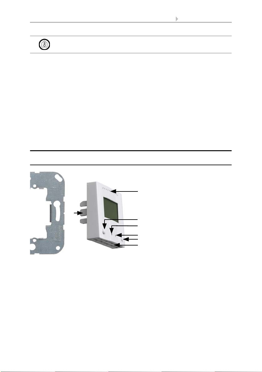
2.3. Construction of the sensor
2.3.1. Housing
Fig. 1
1 Baseplate
2Catches
3 Openings for air circulation
4Key
5 Programming LED (recessed)
6 Programming button
(recessed) for teaching the
device
7Key
8 Openings for air circulation
(LOWER)
3
24
6
7
5
8
1

6 Display and operation at the device
Indoor sensor KNX TH-B-UP • Software version 3.1 and higher
Version: 22.02.2017 • Technical changes and errors excepted.
2.3.2. Rear view sensor plate with connection
2.4. Assembly of the sensor
First of all fit the socket with connection. Seal inlet pipes to avoid infiltration.
Then screw the base plate onto the socket and position the frame of the switching
programme. Connect the bus line +/- (black-red plug) to the terminals provided on the
sensor board of the sensor. Pin the sensor with the notches on to the metal frame, so
that sensor and frame are fixed.
2.5. Notes on mounting and commissioning
Never expose the device to water (e.g. rain) or dust. This can damage the electronics.
You must not exceed a relative humidity of 95%. Avoid condensation.
After the bus voltage has been applied, the device will enter an initialisation phase
lasting a few seconds. During this phase no information can be received or sent via the
bus.
3. Display and operation at the device
Specifications for the display are set in the ETS and the use of the push buttons is
permitted or disabled.
Basically the display can show a two-row or three-row text (e. g. for measured values)
or a tempertuare controller. You can switch between the two types by pressing one of
the buttons, if this has not been disabled in the ETS.
3.1. Mode display and manual temperature
controller
Depending on the ETS setting selected, the mode display will only display show the
current target value, or the base target value setting with scale display. The manually
adjustable range can be set in the ETS.
Fig. 2
1 KNX terminal BUS +/-
2 Catches
2
1
7 Display and operation at the device
Indoor sensor KNX TH-B-UP • Software version 3.1 and higher
Version: 22.02.2017 • Technical changes and errors excepted.
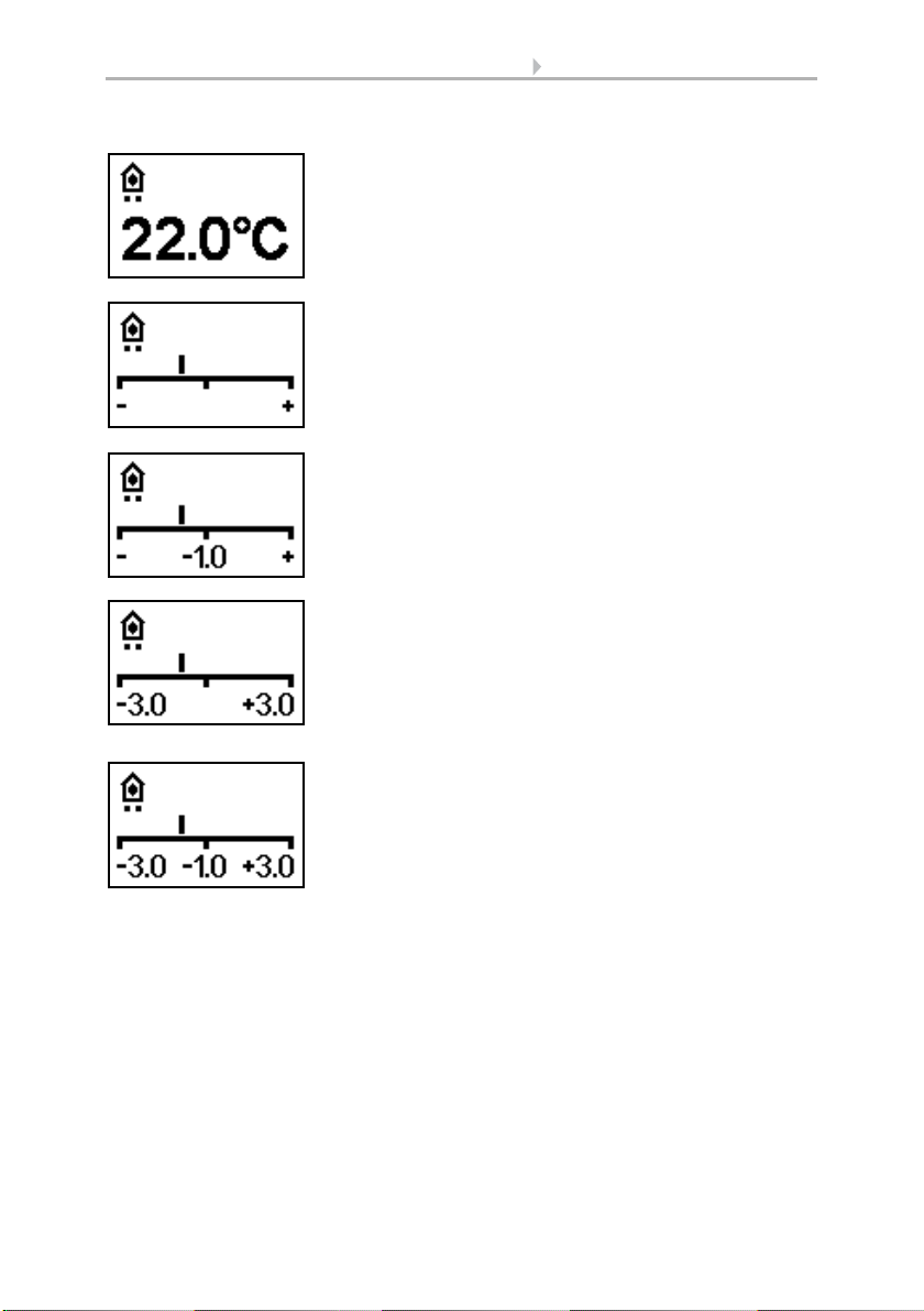
The following display options are available:
Fig. 3
Mode display with current target value and/or base
target value
Fig. 4
Mode display with scale display for adjusting the base
target value.
The control position in the image reads "Base target
value reduced".
Fig. 5
Mode display with scale display and number.
Shows the set target value change.
The control position in the image reads "Base target
value reduced to 1.0°".
Fig. 6
Mode display with scale display and range.
Shows the possible adjustment range (as set in the ETS).
The control position in the image reads "Base target
value reduced".
Fig. 7
Mode display with scale display, range and number.
Displays the possible adjustment range (as set in the
ETS) and the set target value change.
The control position in the image reads "Base target
value reduced to 1.0°".

8 Display and operation at the device
Indoor sensor KNX TH-B-UP • Software version 3.1 and higher
Version: 22.02.2017 • Technical changes and errors excepted.
Symbols
Priority (points)
One point: Priority 1/priority control. It is not possible to adjust the temperature
automation system manually. Neither the target temperature nor the operating modes
can be changed using the buttons on the unit.
Two points: Priority 2. The target temperature and operating mode can be changed
using the buttons.
3.2. Change ambient temperature with the
buttons
If the mode display is active, the target ambient temperature and the operating mode
can be changed manually using the buttons. The button functions can be blocked in
the ETS or be suppressed for Priority 1 operating modes. The individual operating
modes can also be locked for manual selection in the ETS.
Comfort mode.
Comfort (present) target
temperature will be used.
Standby mode.
Standby (absent during day)
target temperature will be used.
Eco mode.
Night target temperature will be
used.
Building protection mode.
Building protection target
temperature will be used. The
symbol will blink when the mode
has been activated but the
activation delay has not yet
expired.
Heating mode.
Heating will be provided.
Cooling mode
Cooling will be provided.
Decrease target
temperature (-)
briefly press
left button
Ambient temperature in the current
mode is decreased.
The sep-size is defined in the ETS
(0.1°C to 5°C).
Increase target
temperature (+)
briefly press
right button
Ambient temperature in the current
mode is increased.
The sep-size is defined in the ETS
(0.1°C to 5°C).
Fig. 8
In "HVAC mode with 2x 8 bits" control mode, points are
shown under the symbol, to indicate the running priority
of the current mode.

9 Display and operation at the device
Indoor sensor KNX TH-B-UP • Software version 3.1 and higher
Version: 22.02.2017 • Technical changes and errors excepted.
Change mode press
left or right button
longer than 2 secs.
Changes between the operating modes
Comfort, Standby, Eco and Building
Protection (if deblocked in the ETS).
Extend Comfort
mode
in Eco mode:
press both buttons
at the same time
longer than 2 secs.
Switches from Eco to Comfort mode
again for a certain time (e. g. if the
rooms are used longer in the evening).
The period is defined in the ETS (up to
10 hours). The time remaining in
Comfort mode is displayed.
This manual suits for next models
3
Table of contents


