manuals.online logo
Brands
  1. Home
  2. •
  3. Brands
  4. •
  5. elsner elektronik
  6. •
  7. Weather Station
  8. •
  9. elsner elektronik P03i-GPS User manual

elsner elektronik P03i-GPS User manual

Weather Station P03i-GPS 1
Weather Station P03i-GPS • Version: 06.08.2020 • Technical changes and errors excepted. • Elsner Elektronik GmbH • Sohlengrund 16 • 75395 Ostelsheim • Germany • www.elsner-elektronik.de • Technical Service: +49 (0) 7033 / 30945-250
EN
P03i-GPS
Weather Station
Technical specifications and installation instructions
Item number 30114
1. Description
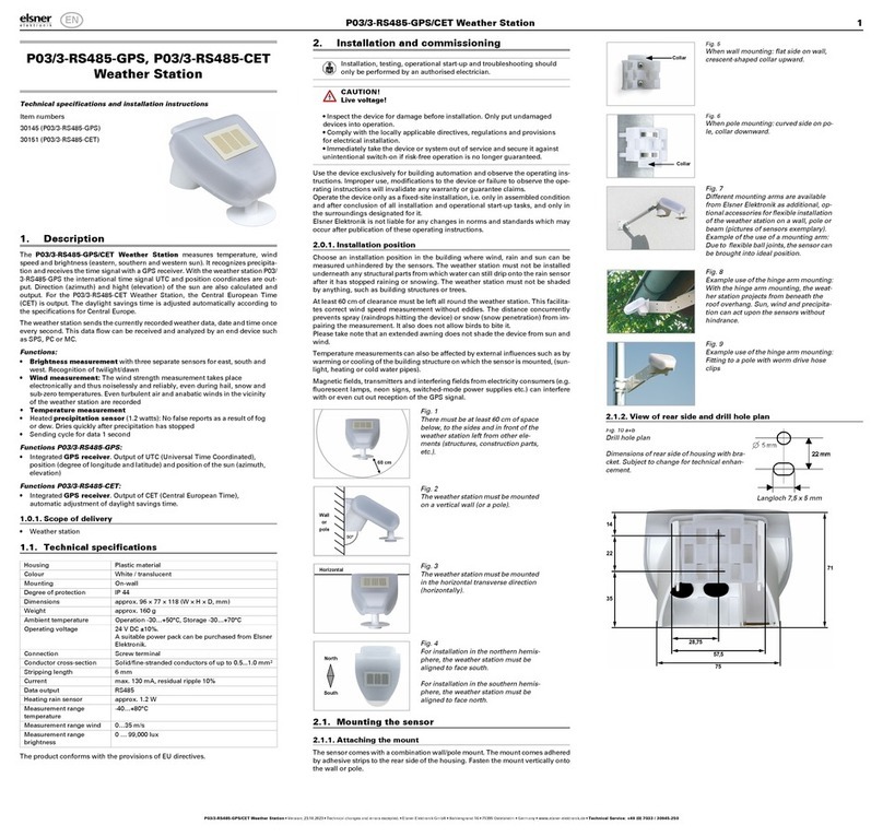
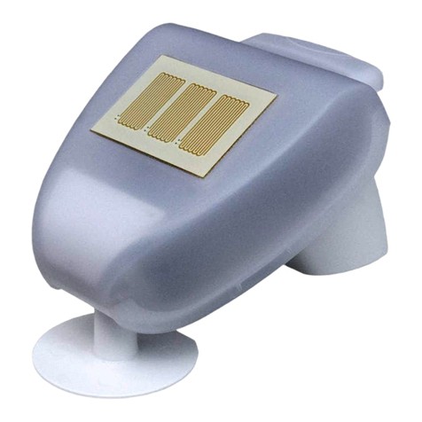
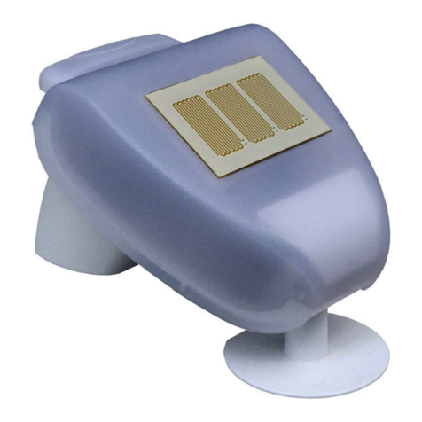
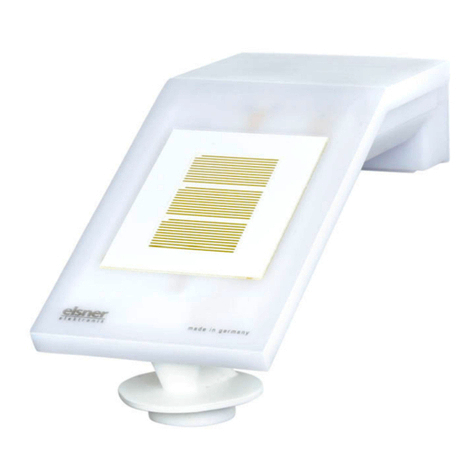
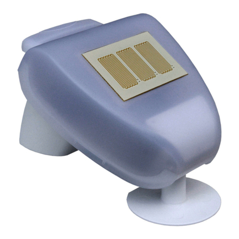
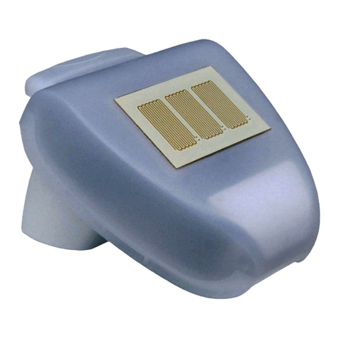
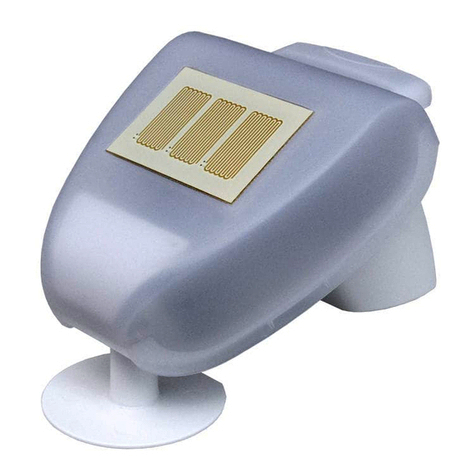
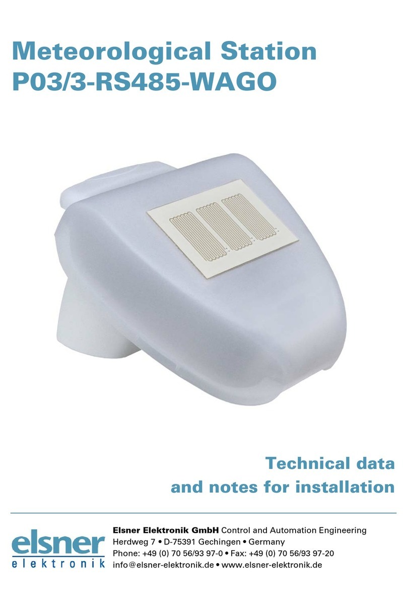
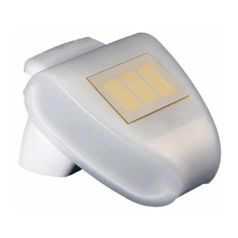
The Weather Station P03i-GPS for WS1/1000 Color/Style and WS1000 Connect
measures temperature, wind speed and brightness. It recognises precipitation and
receives the GPS signal for time and location (international time signal and positi-
on).
The weather station is suitable as accessory for KNX WS1000 Color/Style and as
spare part for WS1 Color/Style and WS1000 Color/Style which were produced from
July 2016 on. For older models of the controls please ask Elsner Elektronik for the
suitable weather station model.
1.1. Scope of delivery
• Weather station with a combination wall/pole mount
1.2. Technical specifications
The product conforms with the provisions of EU directives.
2. Installation and commissioning
2.1. Installation notes
Installation, testing, operational start-up and troubleshooting should
only be performed by an electrician.
CAUTION!
Live voltage!
There are unprotected live components inside the device.
• National legal regulations are to be followed.
• Ensure that all lines to be assembled are free of voltage and take
precautions against accidental switching on.
• Do not use the device if it is damaged.
• Take the device or system out of service and secure it against
unintentional use, if it can be assumed, that risk-free operation is
no longer guaranteed.
The device is only to be used for the intended purpose described in this manual. Any
improper modification or failure to follow the operating instructions voids any and
all warranty and guarantee claims.
After unpacking the device, check it immediately for possible mechanical damage.
If it has been damaged in transport, inform the supplier immediately.
The device may only be used as a fixed-site installation; that means only when as-
sembled and after conclusion of all installation and operational start-up tasks and
only in the surroundings designated for it.
Elsner Elektronik is not liable for any changes in norms and standards which may
occur after publication of these operating instructions.
2.2. Installation position
Choose an installation position in the building where wind, rain and sun can be mea-
sured unhindered by the sensors. The weather station must not be installed under-
neath any structural parts from which water can still drip onto the rain sensor after
it has stopped raining or snowing. The weather station must not be shaded by an-
ything, such as building structures or trees.
At least 60 cm of clearance must be left all round the weather station. This facilitates
correct wind speed measurement without eddies. The distance concurrently pre-
vents spray (raindrops hitting the device) or snow (snow penetration) from impai-
ring the measurement. It also does not allow birds to bite it.
Please take note that an extended awning does not shade the device from sun and
wind.
Temperature measurements can also be affected by external influences such as by
warming or cooling of the building structure on which the sensor is mounted, (sun-
light, heating or cold water pipes).
Magnetic fields, transmitters and interfering fields from electricity consumers (e.g.
fluorescent lamps, neon signs, switched-mode power supplies etc.) can interfere
with or even cut out reception of the GPS signal.
2.3. Attaching the mount
The weather station comes with a combination wall/pole mount. The mount comes
adhered by adhesive strips to the rear side of the housing.
Fasten the holder vertically to the wall or pole.
Housing Plastic material
Colour White / translucent
Mounting On-wall
Protection category IP 44
Dimensions approx. 96 x 77 x 118 (W x H x D, mm)
Weight approx. 160 g
Ambient temperature Operation -30…+50°C, Storage -30…+70°C
Operating voltage 24 V DC
Heating rain sensor approx. 1.2 W
Measurement range
temperature
-40…+80°C
Resolution (tempera-
ture)
0.1°C
Accuracy (temperature) ±1.5°C at -25…+80°C
Measurement range
wind
0…35 m/s
Resolution (wind) 0,1 m/s
Accuracy (wind) at ambient temperature -20…+50°C:
±22% of the measurement value when inci-
dent flow is
from 45…315°
±15% of the measurement value when inci-
dent flow is
from 90…270°
(Frontal incident flow corresponds to 180°)
Measurement range
brightness
0 lux ... 99.000 lux
Resolution (brightness) 1 lux at 0 … 999 lux
1 klux at 1 … 99 klux
Accuracy (brightness) ± 35%
Fig. 1
There must be at least 60 cm of space
below, to the sides and in front of the
weather station left from other ele-
ments (structures, construction parts,
etc.).
60 cm
Fig. 2
The weather station must be mounted
on a vertical wall (or a pole).
Wall
or
pole
Fig. 3
The weather station must be mounted
in the horizontal transverse direction
(horizontally).
Horizontal
Fig. 4
For installation in the northern hemis-
phere, the weather station must be
aligned to face south.
For installation in the southern hemis-
phere, the weather station must be
aligned to face north.
North
South
Fig. 5
For wall mounting: Flat side to the wall,
crescent moon-shaped crosspiece facing
up.
Collar
Fig. 6
For pole mounting: curved side to the
pole, crosspiece facing down.
Collar
Weather Station P03i-GPS 2
Weather Station P03i-GPS • Version: 06.08.2020 • Technical changes and errors excepted. • Elsner Elektronik GmbH • Sohlengrund 16 • 75395 Ostelsheim • Germany • www.elsner-elektronik.de • Technical Service: +49 (0) 7033 / 30945-250
2.3.1. Rear view and drill sketch
2.4. Preparation of the weather station
The weather station lid with the rain sensor latches into place on the lower edge to
the right and left. Remove the lid from the weather station. Proceed carefully to avo-
id tearing off the cable connection between the circuit board in the lower section and
the rain sensor in the lid (cable with plug).
Lead the connection cable through the rubber seal on the underside of the weather
station and connect it to the terminals provided.
The power supply cable to the weather station should be a maximum of 300 m long.
The connection is made with a standard, UV-resistant telephone cable (A-2Y(L)2Y
2x2x0.6 or A-2Y(L)2Y 2x2x0.8).
2.5. Layout of the circuit board
2.5.1. Mounting the weather station
Close the housing by placing the lid on the lower section. The lid must lock into pla-
ce on the right and left with a distinct click.
For removal purposes, the weather station can be pulled upwards against the resis-
tance of the notches.
3. Installation notes for the weather station
Do not open the weather station when water (rain) can enter into it: Even a few drops
may damage the electronics.
During installation care must be taken that the temperature sensor (small plate on
the underside of the housing) is not damaged. The cable connection between the
plate and the rain sensor should also not be torn off or bent when being connected.
After installation, remove all transport protection stickers present.
The wind measurement can first be output about 30 seconds after applying the sup-
ply voltage.
3.1. Maintenance of the weather station
WARNING!
Risk of injury caused by components moved automatically!
The automatic control can start system components and place people in
danger (e.g. moving windows/awnings if a rain/wind alarm has been
triggered while cleaning).
• Always isolate the device from the mains for servicing and cleaning.
The device must regularly be checked for dirt twice a year and cleaned if necessary.
In case of severe dirt, the sensor may not work properly anymore.
ATTENTION
The device can be damaged if water penetrates the housing.
• Do not clean with high pressure cleaners or steam jets.
4. Disposal
After use, the device must be disposed of or recycled in accordance with the legal
regulations. Do not dispose of it with the household waste!
Fig. 7
Different mounting arms are available
from Elsner Elektronik as additional, op-
tional accessories for flexible installation
of the weather station on a wall, pole or
beam.
Example of the use of a mounting arm:
Due to flexible ball joints, the sensor can
be brought into ideal position.
Fig. 8
Example use of the hinge arm mounting:
With the hinge arm mounting, the weat-
her station projects from beneath the
roof overhang. Sun, wind and precipita-
tion can act upon the sensors without
hindrance.
Fig. 9
Example use of the hinge arm mounting:
Fitting to a pole with worm drive hose
clips
Oblong hole 7,5 x 5
Fig. 10 a+b
Drill sketch.
Dimensions of the rear side of the hou-
sing with holder, dimensions in mm. Di-
vergences are possible for technical
reasons.
Fig. 11
1 Cover with rain sensor
2 Cover snaps
3 Bottom part of housing
1
2
3
Unsnap cover and
remove upwards
Fig. 12
1 Slot for control unit/vol-
tage connection, 1: +24
V DC | 2: GND
terminal configuration
independent from pola-
rity
2 Cable connection to the
precipitation sensor in
the housing lid
3 GPS reception LED mo-
nitor
2
3
1
Fig. 13
Check that the lid and lower section
have properly latched into place! The
diagram shows the closed weather
station from below.
Fastening
Fig. 14
Push the housing from above into the
fitted holder. In doing this, the studs in
the holder must click in to the tracks
on the housing.

This manual suits for next models

1

Other elsner elektronik Weather Station manuals

elsner elektronik P03/3-Modbus Guide

elsner elektronik

elsner elektronik P03/3-Modbus Guide

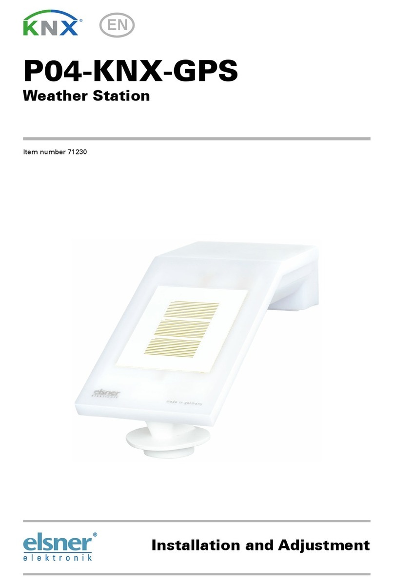
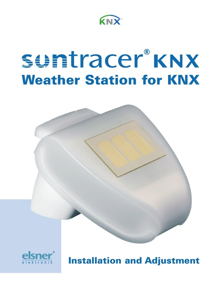
elsner elektronik Suntracer KNX basic User manual

elsner elektronik

elsner elektronik Suntracer KNX basic User manual

elsner elektronik P04/3-RS485 Guide

elsner elektronik

elsner elektronik P04/3-RS485 Guide

elsner elektronik Suntracer KNX-GPS light User manual

elsner elektronik

elsner elektronik Suntracer KNX-GPS light User manual

elsner elektronik P03/3-RS485 Instruction manual

elsner elektronik

elsner elektronik P03/3-RS485 Instruction manual

elsner elektronik P04-KNX-GPS Guide

elsner elektronik

elsner elektronik P04-KNX-GPS Guide

elsner elektronik P03/3-RS485-CET User manual

elsner elektronik

elsner elektronik P03/3-RS485-CET User manual

elsner elektronik Suntracer KNX basic Guide

elsner elektronik

elsner elektronik Suntracer KNX basic Guide

elsner elektronik P03/3-RS485-GPS User manual

elsner elektronik

elsner elektronik P03/3-RS485-GPS User manual

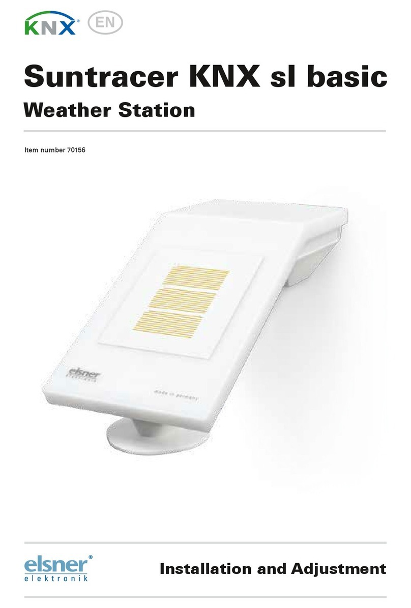
elsner elektronik Suntracer KNX sl basic User manual

elsner elektronik

elsner elektronik Suntracer KNX sl basic User manual

elsner elektronik Suntracer KNX basic Guide

elsner elektronik

elsner elektronik Suntracer KNX basic Guide

elsner elektronik Suntracer KNX-GPS light Guide

elsner elektronik

elsner elektronik Suntracer KNX-GPS light Guide

elsner elektronik P03/3-RS485-WAGO User manual

elsner elektronik

elsner elektronik P03/3-RS485-WAGO User manual

elsner elektronik P03/3 User manual

elsner elektronik

elsner elektronik P03/3 User manual

elsner elektronik P03/3 User manual

elsner elektronik

elsner elektronik P03/3 User manual

elsner elektronik Suntracer KNX basic User manual

elsner elektronik

elsner elektronik Suntracer KNX basic User manual

elsner elektronik Suntracer KNX sl basic Guide

elsner elektronik

elsner elektronik Suntracer KNX sl basic Guide

Popular Weather Station manuals by other brands
Hyundai WS 2011 WIND instruction manual

Hyundai

Hyundai WS 2011 WIND instruction manual

Bresser ClimateTemp NDH instruction manual

Bresser

Bresser ClimateTemp NDH instruction manual

National Geographic 9070300 instruction manual

National Geographic

National Geographic 9070300 instruction manual

Vitek VT-6410 Manual instruction

Vitek

Vitek VT-6410 Manual instruction

La Crosse Technology 308-1417v3 Setup guide

La Crosse Technology

La Crosse Technology 308-1417v3 Setup guide

Espressif ESP8266 Series user guide

Espressif

Espressif ESP8266 Series user guide

Davis Instruments Energy EnviroMonitor installation manual

Davis Instruments

Davis Instruments Energy EnviroMonitor installation manual

Crosse Technology WS-1612 Operation manual

Crosse Technology

Crosse Technology WS-1612 Operation manual

Oregon Scientific BAR806 user manual

Oregon Scientific

Oregon Scientific BAR806 user manual

La Crosse Technology 308-2316 instruction manual

La Crosse Technology

La Crosse Technology 308-2316 instruction manual

La Crosse Technology 9730IT instruction manual

La Crosse Technology

La Crosse Technology 9730IT instruction manual

Explore Scientific WSH1008 instruction manual

Explore Scientific

Explore Scientific WSH1008 instruction manual

Hama TH50 user manual

Hama

Hama TH50 user manual

Alecto WS-1150 user guide

Alecto

Alecto WS-1150 user guide

Ventus C6070A user manual

Ventus

Ventus C6070A user manual

Foshk HP3000 Operation manual

Foshk

Foshk HP3000 Operation manual

Oregon Scientific BAR800 user manual

Oregon Scientific

Oregon Scientific BAR800 user manual

Kestrel 3500 Series instruction manual

Kestrel

Kestrel 3500 Series instruction manual

manuals.online logo
manuals.online logoBrands
  • About & Mission
  • Contact us
  • Privacy Policy
  • Terms and Conditions

Copyright 2025 Manuals.Online. All Rights Reserved.