Elsner KNX B4-UP Guide
Installation and Adjustment
EN
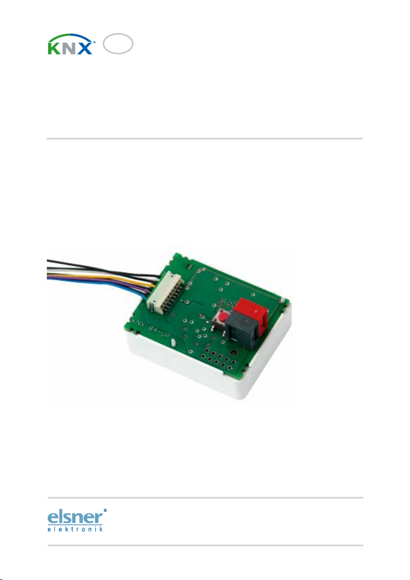
KNX B4-UP
Button Interface
Item number 70250
Elsner Elektronik GmbH Control and AutomationTechnology
Sohlengrund 16
75395 Ostelsheim Phone +49(0)7033/ 30945-0 info@elsner-elektronik.de
Germany Fax +49(0) 7033/ 30945-20 www.elsner-elektronik.de
Technical support: +49 (0) 70 33 / 30 945-250

1 Contents
Elsner Elektronik GmbH • Sohlengrund 16 • 75395 Ostelsheim • Germany
KNX B4-UP button interface • from software version 0.1.0, ETS programme version 1.0
Status: 24.08.2016 • Subject to technical changes. Errors excepted.
1. Description ........................................................................................... 3
1.1. Technical data ........................................................................................................... 3
2. Installation and Commissioning ........................................................... 3
2.1. Installation notes ...................................................................................................... 3
2.2. Installation location .................................................................................................. 4
2.3. Device/connection design ........................................................................................ 5
3. Transfer protocol ................................................................................. 6
3.1. List of all communications objects ......................................................................... 6
4. Parameter settings ............................................................................... 8
4.1. Behaviour on power failure/ restoration of power ................................................ 8
4.2. General settings ....................................................................................................... 8
4.3. Input 1...4 .................................................................................................................. 8
4.3.1. Control modes for drive control ................................................................ 12
2 Clarification of signs
This manual is amended periodically and will be brought into line with new software
releases. The change status (software version and date) can be found in the contents footer.
If you have a device with a later software version, please check
www.elsner-elektronik.de in the menu area "Service" to find out whether a more up-to-
date version of the manual is available.
Clarification of signs used in this manual
Installation, inspection, commissioning and troubleshooting of the device
must only be carried out by a competent electrician.
Safety advice.
Safety advice for working on electrical connections, components,
etc.
DANGER! ... indicates an immediately hazardous situation which will lead to
death or severe injuries if it is not avoided.
WARNING! ... indicates a potentially hazardous situation which may lead to
death or severe injuries if it is not avoided.
CAUTION! ... indicates a potentially hazardous situation which may lead to
trivial or minor injuries if it is not avoided.
ATTENTION! ... indicates a situation which may lead to damage to property if it is
not avoided.
ETS In the ETS tables, the parameter default settings are marked by
underlining.

3 Description
KNX B4-UP button interface • Status: 24.08.16 • Technical Changes and Errors excepted.
1. Description
The KNX B4-UP button interface has four binary inputs for operating conventional
manual buttons in the KNX bus system. Auxiliary contacts, such as window contacts
for locking monitoring, can also be integrated via the interface.
Functions:
• 4 binary inputs for potential-free contacts
1.1. Technical data
The product conforms with the provisions of EU directives.
2. Installation and Commissioning
2.1. Installation notes
Installation, testing, operational start-up and troubleshooting should
only be performed by an electrician.
CAUTION!
Live voltage!
There are unprotected live components inside the device.
• National legal regulations are to be followed.
Mounting Installation
Protection category IP 00
Dimensions ca. 38 x 47 x 24 (W x H x D, mm)
Weight approx. 20 g
Ambient temperature Operation -20…+70 °C, storage -55…+90°C
Ambient humidity max. 95% RH, avoid condensation
Operating voltage bus voltage
Bus current max. 10 mA
Data output KNX +/- bus connector terminal
BCU type unit's own microcontroller
PEI type 0
Group addresses max. 200
Assignments max. 200
Communication objects 37
Inputs 4 x binary inputs (for potential-free contacts),
with 300 mm connection line,
extendable to a maximum of 10 m

4 Installation and Commissioning
KNX B4-UP button interface • Status: 24.08.16 • Technical Changes and Errors excepted.
• Ensure that all lines to be assembled are free of voltage and take
precautions against accidental switching on.
• Do not use the device if it is damaged.
• Take the device or system out of service and secure it against
unintentional use, if it can be assumed, that risk-free operation is no
longer guaranteed.
The device is only to be used for its intended purpose. Any improper modification or
failure to follow the operating instructions voids any and all warranty and guarantee
claims.
After unpacking the device, check it immediately for possible mechanical damage. If it
has been damaged in transport, inform the supplier immediately.
The device may only be used as a fixed-site installation; that means only when
assembled and after conclusion of all installation and operational start-up tasks and
only in the surroundings designated for it.
Elsner Elektronik is not liable for any changes in norms and standards which may occur
after publication of these operating instructions.
2.2. Installation location
The device must only be installed and operated in dry, indoor spaces.
Avoid condensation.
5 Installation and Commissioning
KNX B4-UP button interface • Status: 24.08.16 • Technical Changes and Errors excepted.
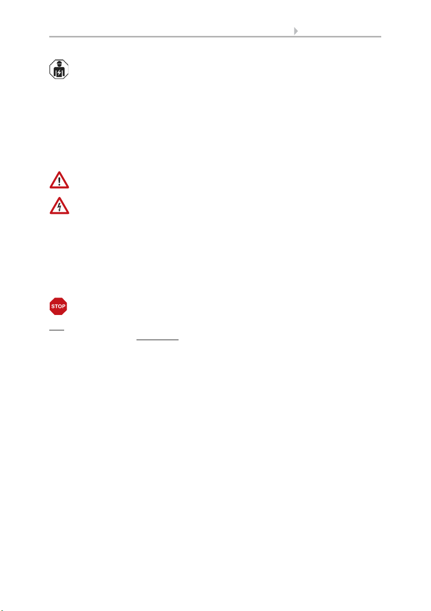
2.3. Device/connection design
1
1 KNX bus plug
2 Programming buttons
3 Binary contact coupling
4 Plug binary contact cable
5 Binary contact connecting wires
Pin assignment:
black (4x): - ("minus")
white: contact 1
yellow: contact 2
pink: contact 3
blue: contact 4
2
3
4
5

6 Transfer protocol
KNX B4-UP button interface • Status: 24.08.16 • Technical Changes and Errors excepted.
3. Transfer protocol
3.1. List of all communications objects
Abbreviation flags:
C Communication
R Read
WWrite
T Transfer
UUpdate
No. Text Function Flags DPT type Size
0 Software version Readable R-CT [217.1] DPT_Version 2 bytes
1 Input 1 - Extended Input /
Output
RWCT [1.8] DPT_UpDown 1 bit
2 Input 1 - Short Output R-CT [1.10] DPT_Start 1 bit
3 Input 1 - Switching Input /
Output
RWCT [1.1] DPT_Switch 1 bit
4 Input 1 - Relative dimming Input /
Output
RWCT [3.7] DPT_Con-
trol_Dimming
4 bit
5 Input 1 - 8-bit encoder Output R-CT [5] 5.xxx 1 byte
6 Input 1 - Temperature
encoder
Output R-CT [9.1] DPT_Val-
ue_Temp
2 bytes
7 Input 1 - Brightness
encoder
Output R-CT [9.4] DPT_Value_Lux 2 bytes
8 Input 1 - Scene Output R-CT [18.1] DPT_Scene-
Control
1 byte
9 Input 1 - Block Input -WC- [1.3] DPT_Enable 1 bit
10 Input 2 - Extended Input /
Output
RWCT [1.8] DPT_UpDown 1 bit
11 Input 2 - Short Output R-CT [1.10] DPT_Start 1 bit
12 Input 2 - Switching Input /
Output
RWCT [1.1] DPT_Switch 1 bit
13 Input 2 - Relative dimming Input /
Output
RWCT [3.7] DPT_Con-
trol_Dimming
4 bit
14 Input 2 - 8-bit encoder Output R-CT [5] 5.xxx 1 byte
15 Input 2 - Temperature
encoder
Output R-CT [9.1] DPT_Val-
ue_Temp
2 bytes
16 Input 2 - Brightness
encoder
Output R-CT [9.4] DPT_Value_Lux 2 bytes
17 Input 2 - Scene Output R-CT [18.1] DPT_Scene-
Control
1 byte
18 Input 2 - Block Input -WC- [1.3] DPT_Enable 1 bit
19 Input 3 - Extended Input /
Output
RWCT [1.8] DPT_UpDown 1 bit

7 Transfer protocol
KNX B4-UP button interface • Status: 24.08.16 • Technical Changes and Errors excepted.
20 Input 3 - Short Output R-CT [1.10] DPT_Start 1 bit
21 Input 3 - Switching Input /
Output
RWCT [1.1] DPT_Switch 1 bit
22 Input 3 - Relative dimming Input /
Output
RWCT [3.7] DPT_Con-
trol_Dimming
4 bit
23 Input 3 - 8-bit encoder Output R-CT [5] 5.xxx 1 byte
24 Input 3 - Temperature
encoder
Output R-CT [9.1] DPT_Val-
ue_Temp
2 bytes
25 Input 3 - Brightness
encoder
Output R-CT [9.4] DPT_Value_Lux 2 bytes
26 Input 3 - Scene Output R-CT [18.1] DPT_Scene-
Control
1 byte
27 Input 3 - Block Input -WC- [1.3] DPT_Enable 1 bit
28 Input 4 - Extended Input /
Output
RWCT [1.8] DPT_UpDown 1 bit
29 Input 4 - Short Output R-CT [1.10] DPT_Start 1 bit
30 Input 4 - Switching Input /
Output
RWCT [1.1] DPT_Switch 1 bit
31 Input 4 - Relative dimming Input /
Output
RWCT [3.7] DPT_Con-
trol_Dimming
4 bit
32 Input 4 - 8-bit encoder Output R-CT [5] 5.xxx 1 byte
33 Input 4 - Temperature
encoder
Output R-CT [9.1] DPT_Val-
ue_Temp
2 bytes
34 Input 4 - Brightness
encoder
Output R-CT [9.4] DPT_Value_Lux 2 bytes
35 Input 4 - Scene Output R-CT [18.1] DPT_Scene-
Control
1 byte
36 Input 4 - Block Input -WC- [1.3] DPT_Enable 1 bit
No. Text Function Flags DPT type Size

8 Parameter settings
KNX B4-UP button interface • Status: 24.08.16 • Technical Changes and Errors excepted.
4. Parameter settings
4.1. Behaviour on power failure/ restoration of
power
Behaviour following a failure of the bus power supply:
The device sends nothing.
Behaviour on bus restoration of power and following programming or reset:
The device sends all outputs according to their send behaviour set in the parameters
with the delays established in the "General settings" parameter block.
4.2. General settings
Set the maximum telegram rate.
4.3. Input 1...4
Interface inputs can be configured as switches, drive controller, dimmer, for transmit-
ting values and for scenario recall/storage.
There are blocking objects for all functions, blocking the input at 1 and releasing it at
0. When activating and deactivating the block, a telegram can be sent to the bus in each
instance. There is no cyclic transmission while the block is active.
Maximum telegram rate • 1 telegram per second
• ...
• 5 telegrams per second
• ...
• 20 telegrams per second
Bus function • Switch
• Changeover switch
• Shutter
• Blinds
• Awning
• Window
• Dimmer
• 8-bit encoder
• Temperature encoder
• Brightness encoder
• Scenes
Use blocking objects No • Yes
9 Parameter settings
KNX B4-UP button interface • Status: 24.08.16 • Technical Changes and Errors excepted.
Input as switch:
If a button with switch function is assigned to the input, select the bus function
"Switch" and specify which value is sent when pressing/releasing the button and when
it will be sent.
Blocking objects block the input at 1 and release it at 0. When activating and deactivat-
ing the block, a telegram can be sent to the bus in each instance. There is no cyclic
transmission while the block is active.
Input as changeover switch:
If a button with switch function is assigned to the input, select the bus function
"Changeover Switch" and specify if the button should switch when pressed/released.
When activating the block once • send 0
• send 1
• Do not send message
When deactivating the block once • send 0
• send 1
• Do not send message
Function Switch
Command when pressing the button • send 0
• send 1
• do not send telegram
Command when releasing the button • send 0
• send 1
• do not send telegram
Send value • no change
• for change to 1
• for change to 0
• for change and cyclical
• for change to 1 and cyclical
• for change to 0 and cyclical
Cycle
(if sent cyclical)
5 s • 10 s • 30 s • 1 min • 2 min • 5 min • 10
min • 20 min • 30 min • 1 h • 2 h
Use blocking objects No • Yes
When activating the block once • send 0
• send 1
• Do not send message
When deactivating the block once • send 0
• send 1
• Do not send message
Function Changeover Switch

10 Parameter settings
KNX B4-UP button interface • Status: 24.08.16 • Technical Changes and Errors excepted.
Blocking objects block the input at 1 and release it at 0. Nothing is transferred to the
bus while the block is active.
Input to shutter, blinds, awning or window control:
If the input to the drive control is used via the bus, select the bus function "shutter",
"awning", "blinds" or "window" and specify the button function and control mode.
*There is a detailed description of the setting options for the individual control
modes in chapter Control modes for drive control, page 12.
Blocking objects block the input at 1 and release it at 0. Nothing is transferred to the
bus while the block is active.
Input as dimmer:
If the input is used as a dimmer, select the bus function "Dimmer" and specify the but-
ton function, time interval (switching/dimming) and if requested, the repeat interval for
a long button press.
Command when pressing the button • Switching
• do not send telegram
Command when releasing the button • Switching
• do not send telegram
Use blocking objects No • Yes
Function Shutter / blinds / awning / window
Button function Up • Down
Up • Down • Up/
Down
On • Off • On/Off
Open • Closed •
Open/Closed
(shutter)
(blinds)
(awning)
(window)
Control mode* • Standard
• Standard inverted
• Comfort mode
• Dead man's switch
Use blocking objects No • Yes
Function Dimmer
Button function brighter • darker • brighter/darker
Time between switching and dimming
(in 0.1 s)
1...50; 5
Repeat the dimm command no • yes

11 Parameter settings
KNX B4-UP button interface • Status: 24.08.16 • Technical Changes and Errors excepted.
Blocking objects block the input at 1 and release it at 0. Nothing is transferred to the
bus while the block is active.
Input 8 bit encoder:
If the input is to be used as an 8bit encoder, select the "8 bit encoder" bus function and
specify which value will be sent.
Blocking objects block the input at 1 and release it at 0. Nothing is transferred to the
bus while the block is active.
Input as temperature encoder:
If the input is used as a temperature encoder, then choose the bus function "Tempera-
ture encoder" and specify which value between -30°C and +80°C will be sent.
By sending a temperature value, the target value of the temperature control may be
changed for example.
Blocking objects block the input at 1 and release it at 0. Nothing is transferred to the
bus while the block is active.
Input as brightness encoder:
If the input is assigned and shall be used as a brightness encoder (e.g. threshold value
of a sun sensor), select "brightness encoder" and specify which value will be sent.
Blocking objects block the input at 1 and release it at 0. Nothing is transferred to the
bus while the block is active.
Repeat the dimm command
for a long button press
(if dimm command is repeated)
every 0.1 s • every 2 sec; every 0,5 sec
Dim by
(if dimm command is repeated)
1,50% • 3% • 6 % • 12,50% • 25% • 50%
Use blocking objects No • Yes
Function 8 bit encoder
Value 0...255
Use blocking objects No • Yes
Function Temperature encoder
Temperature in 0.1°C -300...800; 200
Use blocking objects No • Yes
Function Brightness encoder
Brightness in klux 0...100; 20
Use blocking objects No • Yes

12 Parameter settings
KNX B4-UP button interface • Status: 24.08.16 • Technical Changes and Errors excepted.
Input for scene control:
If scenes are called and saved with the input, then choose the "Scenes" bus function
and specify the saving, time difference (call/save) and scene number.
Blocking objects block the input at 1 and release it at 0. Nothing is transferred to the
bus while the block is active.
4.3.1. Control modes for drive control
If inputs are being used as switches to operate shades or windows, then various con-
trol modes can be set.
Standard:
If briefly operated, the drive will move incrementally or stops. If operated longer, the
drive will move up to the end position. The time difference between "short" and "long"
is set individually.
Standard inverted:
When pushed shortly, the drive moves up to the end position. When pushed for longer,
the drive moves incrementally or stops. The time difference between "short" and
"long" and the repeat interval is set individually.
Function Scenes
Button operation • without saving
• with saving
Time between calling and saving in 0.1 sec-
onds
(only if selected "with saving")
1...50; 10
Scene No. 0...127
Use blocking objects No • Yes
Control mode • Standard
• Standard inverted
• Comfort mode
• Dead man’s switch
Control mode Standard
Behavior during button operation:
short = stop/increment long = Up or Down
Time between short and long
in 0.1 seconds
1...50; 10
Control mode Standard inverted
Behavior during button operation:
short = Up or Down long = Stop/Step
13 Parameter settings
KNX B4-UP button interface • Status: 24.08.16 • Technical Changes and Errors excepted.
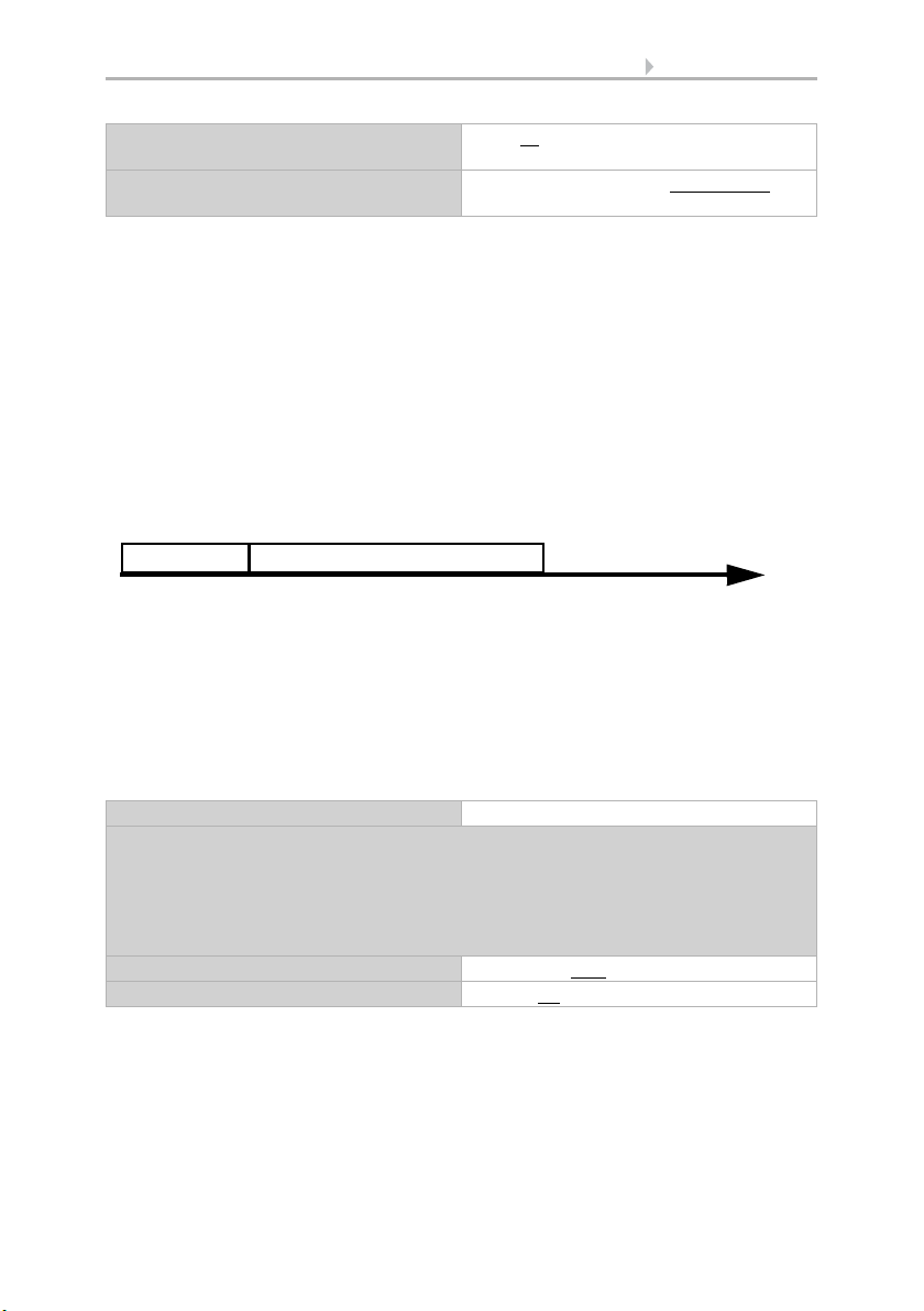
Comfort mode:
In the comfort mode pushing the button briefly, a bit longer and long will trigger dif-
ferent responses of the drive. The time intervals are set individually.
By pushing the button (shorter than adjustable time 1) the drive will be positioned
(resp. stopped) incrementally.
If the drive is to be moved a bit farther, then a little longer push is needed (longer than
time 1 but shorter than time 1+2). The drive stops immediately when releasing the but-
ton.
If the drive must be moved independently into the end position, the button is released
only after times 1 + 2 have expired. The move can be stopped by briefly pushing.
Dead man's switch:
The drive moves as soon as the button is pushed and stops as soon as the button is
released.
Time between short and long
in 0.1 seconds
1...50; 10
Repeat the step command
for a long button press
every 0.1 s • every 2 sec; every 0.5 sec
Point in time 0: Push of button, start of time 1
Release before time 1 expired: step (or stop if drive is moving)
Point in time 1: End of time 1, start of time 2
Moving command
Release after time 1 expired
but before time 2 expires: Stop
Release after time 1 + 2 expired: Move into end position
Control mode Comfort mode
Behavior during button operation:
Button is pushed and
released before time 1 expired = stop/step
held longer than time 1 = Up or Down
released between time 1 and 1-2= stop
released after time 1 +2 = no more stop
Time 1 0.0s ... • 2 s; 0.4 s
Time 2 0 s • 2 s; 2 s
Time 1 Time 2
01 1+2
Fig. 1
Time interval comfort mode diagram

14 Parameter settings
KNX B4-UP button interface • Status: 24.08.16 • Technical Changes and Errors excepted.
Control mode Dead man's switch
Behavior during button operation:
Push button = Up or Down command
Release button = Stop command

WS1 Style
Control System for Buildings and for Conservatories
Installation and Operation
EN
WS1000 Style
Control System for Buildings and for Conservatories
including WS1Style-PF and WS1000Style-PF
WS1 Style 60180-60184 (white), 60185-60189 (black). WS1 Style PF 60191-60194 (white), 60196-60199 (black)
WS1000 Style 60201-60204 (white), 60206-60209 (black). WS1000 Style PF 60211-60214 (white), 60216-60219 (black)
Elsner Elektronik GmbH Control and AutomationTechnology
Sohlengrund 16
75395 Ostelsheim Phone +49(0) 7033/ 30945-0 info@elsner-elektronik.de
Germany Fax +49(0) 7033/ 30945-20 www.elsner-elektronik.de
Technical support: +49 (0) 70 33 / 30 945-250
Table of contents
Other Elsner Recording Equipment manuals


Popular Recording Equipment manuals by other brands

Acrosser Technology
Acrosser Technology AR-B2201 manual

Roland
Roland Sonar V-Studio 100 Service manual

Lenze
Lenze E94AZMS Series Mounting instructions

TC-Helicon
TC-Helicon GO VOCAL quick start guide

Technical Solutions
Technical Solutions Ultra Plus Information sheet

SEW-Eurodrive
SEW-Eurodrive Movidrive MDX61B manual


