Zoom Pro 4040 User manual

Safety Precautions •••••••••••••••••••••••••••••••••••••••••••••••••••••••••••••••••••••••••••••••••••••••••••••• 2
Usage Precautions••••••••••••••••••••••••••••••••••••••••••••••••••••••••••••••••••••••••••••••••••••••••••••••• 2
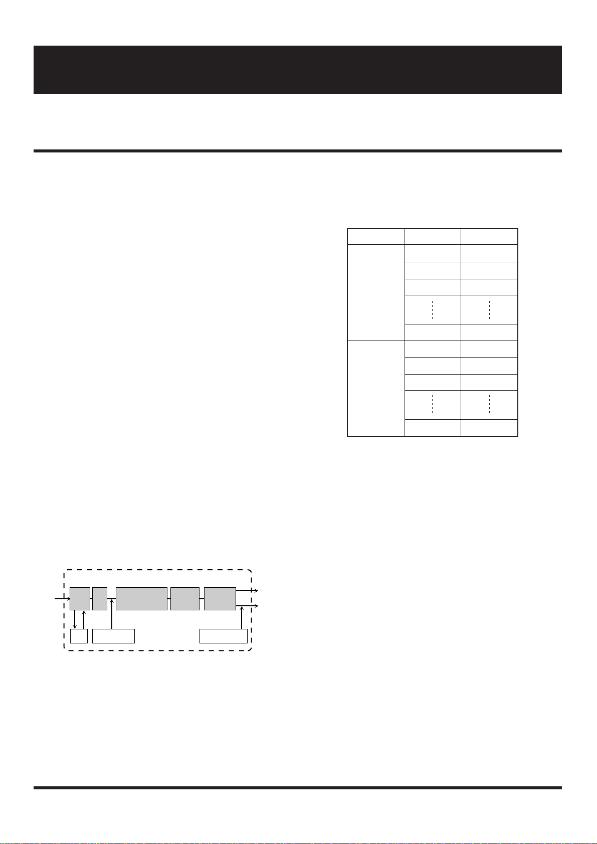
Getting Familiar With Some Basic Terms •••••••••••••••••••••••••••••••••••••••••••••••••••••••••••••• 3
Names and Functions of Controls and Connectors •••••••••••••••••••••••••••••••••••••••••••••••••• 4
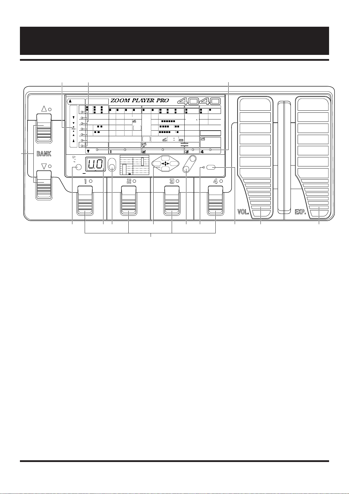
Front Panel •••••••••••••••••••••••••••••••••••••••••••••••••••••••••••••••••••••••••••••••••••••••••••••••••••• 4
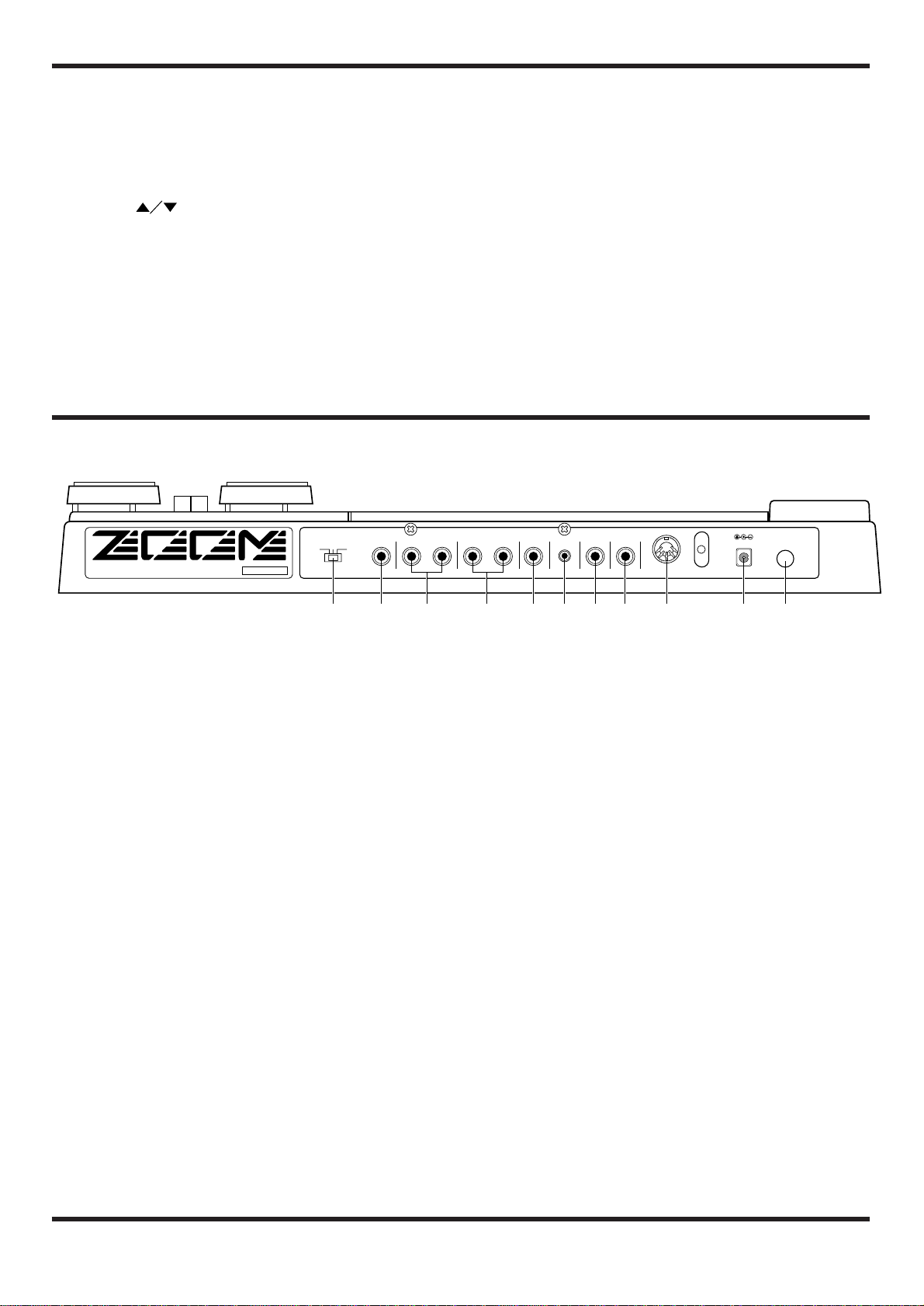
Rear Panel ••••••••••••••••••••••••••••••••••••••••••••••••••••••••••••••••••••••••••••••••••••••••••••••••••••• 5
Connection Examples•••••••••••••••••••••••••••••••••••••••••••••••••••••••••••••••••••••••••••••••••••••••••• 6
Connection to one guitar amplifier (Example 1) •••••••••••••••••••••••••••••••••••••••••••••••••••••••••• 6
Connection to two guitar amplifiers (Example 2)••••••••••••••••••••••••••••••••••••••••••••••••••••••••• 6
Connection to Head phone (Example 3) ••••••••••••••••••••••••••••••••••••••••••••••••••••••••••••••••••• 6
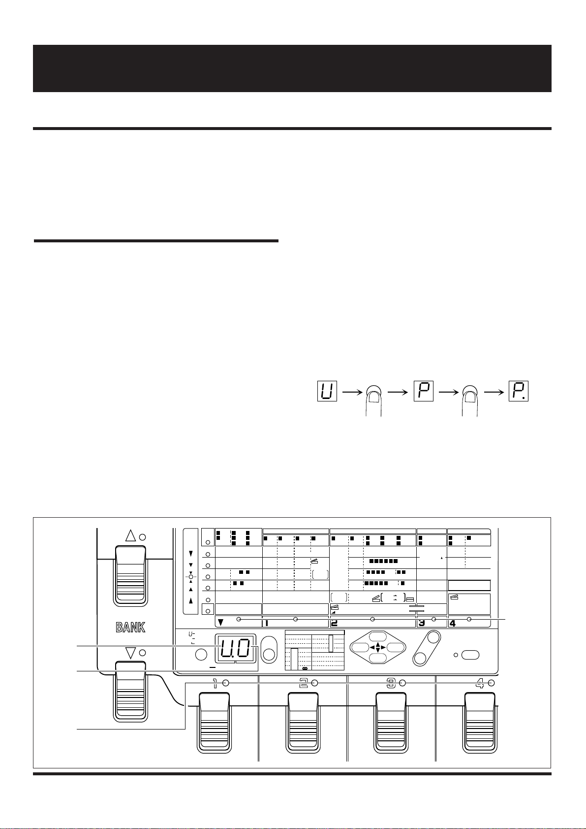
Playing a Patch (Use of the Play Mode) •••••••••••••••••••••••••••••••••••••••••••••••••••••••••••••••• 7
Panel display in Play mode •••••••••••••••••••••••••••••••••••••••••••••••••••••••••••••••••••••••••••••••••• 7
Selecting a patch ••••••••••••••••••••••••••••••••••••••••••••••••••••••••••••••••••••••••••••••••••••••••••••• 7
Useful functions in the Play mode ••••••••••••••••••••••••••••••••••••••••••••••••••••••••••••••••••••••••• 8
Editing a Patch (Use of the Edit Mode) ••••••••••••••••••••••••••••••••••••••••••••••••••••••••••••••••• 10
Entering the Edit mode •••••••••••••••••••••••••••••••••••••••••••••••••••••••••••••••••••••••••••••••••••••• 10
Panel display in Edit mode ••••••••••••••••••••••••••••••••••••••••••••••••••••••••••••••••••••••••••••••••• 10
Editing a patch ••••••••••••••••••••••••••••••••••••••••••••••••••••••••••••••••••••••••••••••••••••••••••••••• 11
Turning effect modules on and off ••••••••••••••••••••••••••••••••••••••••••••••••••••••••••••••••••••••••• 12
Compare •••••••••••••••••••••••••••••••••••••••••••••••••••••••••••••••••••••••••••••••••••••••••••••••••••••• 12
Storing a patch ••••••••••••••••••••••••••••••••••••••••••••••••••••••••••••••••••••••••••••••••••••••••••••••• 12
Effect Types and Parameters ••••••••••••••••••••••••••••••••••••••••••••••••••••••••••••••••••••••••••••••• 13
Effect Module 1: (PRE) ••••••••••••••••••••••••••••••••••••••••••••••••••••••••••••••••••••••••••••••••• 13
Effect Module 2: Equalizer (EQ) ••••••••••••••••••••••••••••••••••••••••••••••••••••••••••••••••••••••• 15
Effect Module 3: Modulation •••••••••••••••••••••••••••••••••••••••••••••••••••••••••••••••••••••••••• 16
Effect Module 4: Delay•••••••••••••••••••••••••••••••••••••••••••••••••••••••••••••••••••••••••••••••••• 20
Effect Module 5: Reverb (REV) ••••••••••••••••••••••••••••••••••••••••••••••••••••••••••••••••••••••• 20
Patch level •••••••••••••••••••••••••••••••••••••••••••••••••••••••••••••••••••••••••••••••••••••••••••••••• 21
About the TOTAL parameters •••••••••••••••••••••••••••••••••••••••••••••••••••••••••••••••••••••••••••••• 21
EXTERNAL LOOP ••••••••••••••••••••••••••••••••••••••••••••••••••••••••••••••••••••••••••••••••••••• 21
EXTERNAL CTRL OUT (External Control) •••••••••••••••••••••••••••••••••••••••••••••••••••••••• 21
MINIMUM VOLUME •••••••••••••••••••••••••••••••••••••••••••••••••••••••••••••••••••••••••••••••••• 22
MIDI CH (MIDI Channel) •••••••••••••••••••••••••••••••••••••••••••••••••••••••••••••••••••••••••••••• 22
EXP. SELECT (Expression Select) •••••••••••••••••••••••••••••••••••••••••••••••••••••••••••••••••••• 22
Edit Mode Application Examples ••••••••••••••••••••••••••••••••••••••••••••••••••••••••••••••••••••••••• 23
Tapping input of delay time •••••••••••••••••••••••••••••••••••••••••••••••••••••••••••••••••••••••••••••••• 23
External effecter loop ••••••••••••••••••••••••••••••••••••••••••••••••••••••••••••••••••••••••••••••••••••••• 23
External control •••••••••••••••••••••••••••••••••••••••••••••••••••••••••••••••••••••••••••••••••••••••••••••• 23
Expression pedal control •••••••••••••••••••••••••••••••••••••••••••••••••••••••••••••••••••••••••••••••••••• 24
Other Functions•••••••••••••••••••••••••••••••••••••••••••••••••••••••••••••••••••••••••••••••••••••••••••••••••• 25
Restoring individual factory preset patches (patch recall) •••••••••••••••••••••••••••••••••••••••••••••• 25
Restoring all factory preset patches (initialize) •••••••••••••••••••••••••••••••••••••••••••••••••••••••••• 25
Volume pedal control ••••••••••••••••••••••••••••••••••••••••••••••••••••••••••••••••••••••••••••••••••••••• 25
MIDI control ••••••••••••••••••••••••••••••••••••••••••••••••••••••••••••••••••••••••••••••••••••••••••••••••• 26
Swapping the pedal functions •••••••••••••••••••••••••••••••••••••••••••••••••••••••••••••••••••••••••••••• 26
Application Examples for Use of Foot Switch and Pedal Switch 1–4 ••••••••••••••••••••••• 27
Using the FS01 ••••••••••••••••••••••••••••••••••••••••••••••••••••••••••••••••••••••••••••••••••••••••••••••• 27
Specifications•••••••••••••••••••••••••••••••••••••••••••••••••••••••••••••••••••••••••••••••••••••••••••••••••••• 28
Contents

Thank you for selecting the ZOOM Player Pro 4040 (hereafter simply called the “4040”).
The 4040 is a sophisticated multi-effect device with the following features and functions:
• A total of 25 built-in individual effects, which can be combined in patches of
up to six effects. 40 preset patches and a user memory for 40 additional
patches offer extraordinary flexibility.
• Integrated volume and expression pedals allow adjustment of output level and
effect settings in real time. This is ideal for use during a live performance.
• Integrated auto-chromatic guitar tuning function lets you quickly and
precisely tune instruments on stage.
• Compression and distortion effects are generated using analog circuitry, to
assure rich and natural-sounding sustain and distortion.
• Send/return Jacks allow connection of external effect devices, and a control
out lets you switch guitar amp channels. You can even program the use of
these connectors as part of a patch, to create sophisticated sound effects.
• MIDI OUT for control of external MIDI devices makes the 4040 convenient as
a system control center.
• By using the optional foot switch FS01, single effect on/off switching during a
performance is possible, for further enhanced playability.
Please take the time to read this manual carefully, in order to get the most out of your 4040 and to
ensure optimum performance and reliability.
1

Safety Precautions
Please observe the following safety tips and precautions to
ensure hazard-free use of the 4040.
• Power requirements
The 4040 is powered by the supplied AC adapter
AD0003/AD0004. To prevent malfunction and safety
hazands, Do not use any other kind of AC adapter.
When using the 4040 in an area with a different line
voltage, please consult your local ZOOM distributor about
acquiring a proper AC adapter.
• Environment
Avoid using your 4040 in environments where it will be
exposed to:
• Extreme temperature
• High humidity or moisture
• Excessive dust or sand
• Excessive vibration or shock
• Handling
Since the 4040 is a precision electronic device, avoid
applying excessive force to the switches and buttons. Also
take care not to drop the unit, and do not subject it to
shock or excessive pressure.
• Alterations
Never open the case of the 4040 or attempt to modify the
product in any way since this can result in damage to the
unit.
• Connecting cables and input and output jacks
You should always turn off the power to the 4040 and all
other equipment before connecting or disconnecting any
cables. Also make sure to disconnect all cables and the
AC adapter before moving the 4040.
Usage Precautions
• Electrical interference
The 4040 uses digital circuitry that may cause interference
and noise if placed too close to other electrical equipment,
such as TV sets and radio receivers. If such problems
occur, move the 4040 further away from the affected
equipment. Also, when fluorescent lights or devices with
built-in motors are close to the 4040, the unit may not
function properly.
• Cleaning
Use a soft, dry cloth to clean the 4040. If necessary,
slightly moisten the cloth. Do not use abrasive cleanser,
wax, or solvents (such as paint thinner or cleaning
alcohol), since these may dull the finish or damage the
surface.
Please keep this manual in a convenient place for future
reference.
2

• Effect Module
The 4040 incorporates five types of effect groups which are
referred to as “effect modules”. Each effect module can be
thought of as a single compact effect. The 4040 therefore
operates like five compact effects connected in series. In
addition, it is also possible to connect external effect
devices.
The 4040 offers the following five effect modules:
• PRE (Analog compressor and distortion effects)
• EQ (Equalizer and wah effects, amp simulation)
• MODULATION (Modulation effects for changing
pitch or sound timbre, such as pedal pitch and flanger)
• DELAY (Delay effects)
• REVERB (Reverberation effects)
• Effect Type
Each effect module contains several effect variations which
are called “effect types”. Each effect module can use one
effect type at a time. For a list of effect types in each effect
module, please see the table on page 10.
• Patches and Groups
The 4040 allows you to use a maximum of five effect
modules simultaneously. A combination of effect modules,
each with individual parameter settings plus the final output
level setting is referred to as a “patch”. The patch also
includes the external effect on/off setting, external control
setting, and expression pedal setting.
The 4040 has two memory areas or “groups” where patches
are stored: the USER group for patches that can be freely
altered and stored by the user, and the PRESET group for
factory defined read-only patches. There are 40 patches in
each group, for a total of 80 patches.
• Bank
The 4040 calls up patches in sets of four, and the foot pedals
serve to switch between patches. Such a set of four patches
is referred to as a “bank”. To select a patch, first specify the
group and the bank number (0 – 9), and then use the foot
pedal switches 1 – 4 to select the patch number.
• Parameter
The elements which determine the sound of an effect are
referred to as “parameters”. Parameter values can be
adjusted for each effect module, to create your own patches
with the 4040.
• Mode
The functions of the 4040 can be roughly divided into three
different categories. These are called “modes”, as described
below.
• Play Mode
In this mode, patches can be selected and played. This is
the default mode of the 4040 when power is turned on.
• Edit (Manual) Mode
In this mode, the parameters of each patch can be edited.
The mode can also serve as a manual mode to switch
effect modules on and off during a performance using the
pedal switches 1 – 4 and the BANK ▼pedal.
• Special Mode
Serves to return some or all patch data to the factory
preset condition.
GROUP BANK No. PATCH No.
0 1 – 4
1 1 – 4
USER 2 1 – 4
9 1 – 4
0 1 – 4
1 1 – 4
PRESET 2 1 – 4
9 1 – 4
PATCH LEVEL
INPUT
PATCH
EXT
OUTPUTPRE EQ MODULATION DELAY REVERB
VOL. PEDAL
3
Getting Familiar With Some Basic Terms
This manual has been written so that it can be easily understood by first-time users. However, the 4040 offers several
special functions which are not available with a conventional effect processor. This section explains some of the terms
used to describe such functions.

4
Front Panel
(1) Tuner LED
Indicates the bypass/tuner condition.
(2) Parameter cursor LED
• In Edit mode
Flashing LED indicates the currently edited parameter.
• In bypass/tuner mode
Serves as a fine tuning meter.
(3) Module cursor LED
• In Play mode
Lit LED indicates which effect module in the current
patch is ON.
• In Edit mode
Lit LED indicates which effect module in the currently
edited patch is ON, and flashing LED indicates the
currently edited effect module.
(4) GROUP key
• In Play mode
Serves to select the memory group for the patch :USER,
PRESET, or BOTH.
• In Edit mode
Serves to compare the currently edited patch with the
patch before editing (compare function). For details,
please refer to page 12.
(5) Display
The display shows vital information for operating the 4040,
such as group and bank numbers of a patch, effect parameter
values and other messages.
(6) STORE key
Serves to store an edited patch with its new parameter and
level settings in the user group.
(7) PARAMETER SELECT keys
Serve to select the parameter to be edited in Edit mode.
(8) VALUE + / - keys
These keys serve to change the value of a setting in any
mode. Tapping the VALUE + key increases the value by one
step, and tapping the VALUE - key decreases the value by
one step. Keeping a key depressed changes the value
continuously. To increase the speed of the change, press the
other key as well.
(9) Edit mode LED
This LED lights up when the 4040 is in the Edit (Manual)
mode.
(10) EDIT (MANUAL) / CANCEL key
Names and Functions of Controls and Connectors
PARAMETER SELECT
ADVANCED GUITAR EFFECTS PROCESSOR
STORE
USER
PRESET
BOTH
p
.
( )
VALUE EDIT(MANUAL)
CANCEL
TUNER CALIB
(435Hz–445Hz)
GROUP GROUP・BANK
(EDIT TUNER VALUE)
/
1: Dirty BEND 9: b3rd
↑
↑
3rd
↑
2: Ham Chokin 10: 1Oct
↓
1Oct
↑
3: Detune 4th
↑
4: 6th
↑
13: 4 Octave
14: Hi-BAND
15: X-fade
16: Scratch
5:
6:
7:
8:
11: 5th
↓
12: 5th2nd
↓
1Oct
↑
1Oct
↓
2Oct
↓
↓
→
→
0
POL–PIT MODE
PRE MODULE
EQ MODULATION DELAY REVERB
EFFECT
COMP
[0– 4]
PARM 2
PARM 3
PARM 4
PARM 5
TOTAL
PARM 1 HIGH
[-7– +7]
TONE
[-7–+7]
ZNR
[0–15]
EXTERNAL LOOP
[0,1] 0=OFF, 1=ON
3 – 8 GAIN
[1–16]
3 – 8 DYNAMICS
[0– 3]
1 EQ
3 ODI
5 DST I 4 ODII
6 DST II
7 LEAD 8 METAL 2 AMP
SIM 3 AUTO 4 PDL
WAH WAH 1 PDL
PIT 2 PIT 3 FLG
6 STEP 4 PHA
7 SLOW 5 TREM
8 CHO 1 MONO
2 PPD 1 HALL
2 ROOM 3 DELAY
LEVEL
[1– 8]
EXTERNAL CONTROL OUT
[1– 4]
MID
[-7– +7]
MIDf
[1–16]
LOW
[-7– +7]
COLOR
[1– 3]
BOX
[1– 3]
DEPTH
[0–10]
TONE
[-7– +7]
FREQ
[1–64] FREQ
EXP.
MODE
0= NORM
1= INV
SENS
[0–10] MODE
[1–16]
(PITCH)
PITCH
[0– 24]
SHIFT
[dn, UP]
FINE
[-5– +5]
BAL
[0– 10]
0= NORM
1= INV EXP.MODE 0= min VAL
1= VAL max
MINIMUM VOLUME
[0–10]
VOL
DEPTH
[0–10]
3 4 5 6 PEAK
[0–10]
1 CLN I
2 CLN II
7 8 BAL.
3 4 5 6 7 MODE
[0, 1] 8 STR
3 4 5 6 7 8 RATE
[1–50]
[0– 10]
(X100mS)
DELAY TIME( )
[0– 99]
(mS)
FEEDBACK
[0– 10]
MIX
[0– 10]
MIDI CH
[1– 16]
TIME
[1– 10]
TONE
[-7– +7]
MIX
[0– 10]
PATCH LEVEL
[0– 50]
TIME
[0– 90] (X10mS)
FEEDBACK
[0– 10]
0= OFF 1= DIST 2= EQ
3= MOD 4= DLY 5= REV
EXP. SELECT
[0– 5]
TUNER
(BYPASS)
♯
♭
DELAY TIME
TAP EDIT
BANK
PRE MODULE
BANK
EQ MODULATION DELAY REVERB
+
–
GLOBAL
(1) (2) (3)
(11)
(4)
(12)
(5) (6) (7) (8) (9) (10) (13) (14)

Pressing this key switches from Play mode to Edit mode.
The Edit mode can also be used as Manual mode to switch
effect modules on and off with the pedal switches 1 – 4 and
the BANK ▼pedal. The key also serves to return from the
Edit mode to the Play mode, and to cancel a store process.
(11) BANK pedal switches
• In Play mode
The ▲pedal selects the next higher bank, and the ▼pedal
the next lower bank.
• In Edit (Manual) mode
The ▲pedal serves to set the delay time of the effect
module. Each tap of the pedal changes the setting by one
step. The ▼pedal serves to switch PRE for the effect
module on and off. The pedal LED lights up when PRE is
on.
(12) Pedal switches 1 - 4
• In Play mode
The pedals serve to select a patch. The respective pedal
LED lights up.
• In Edit (Manual) mode
The pedals serve to switch the effect modules EQ,
MODULATION, DELAY, REVERB on and off. The
respective pedal LED lights up.
(13) VOL (Volume) pedal
Serves to manually control the overall level of a patch.
(14) EXP (Expression) pedal
Serves to control any selected effect parameter in real time.
5
Rear Panel
(1) INPUT GAIN SWITCH
This switch controls the input sensitivity. Select the position
most suited to the connected instrument. For reference,
standard settings are shown below.
H: For guitars with single-coil pickups
M: For guitars with hum-bucking or active type pickups
L: For guitars with very high output
(2) INPUT jack
Serves for connection of an instrument such as electric
guitar or bass.
(3) EXTERNAL SEND/RETURN connectors
Serve for connection of an external effect device. The
send/return loop is inserted in series between the
compressor and distortion sections in the PRE module. The
ON/OFF setting of the send/return loop can be stored as part
of a patch.
(4) OUTPUT L/MONO & R connectors
Serves for connection to a guitar amplifier. To use the 4040
in stereo, connect cables to both jacks. For a monaural
setup, connect the cable to the L/MONO jack.
(5) PHONES jack
Allows connection of a pair of stereo headphones, to
monitor the output of the 4040.
(6) VOLUME control
Adjusts the master volume (overall output level of the
4040). The control affects both the signal at the OUTPUT
connectors and the PHONES jack.
(7) MANUAL connector
This jack serves for connection of the optional foot switch
FS01 which can be used to switch between Play mode and
Manual mode.
(8) EXTERNAL CONTROL OUT connector
This jack can be used to control channel switching of an
external guitar amplifier.
This setting can be stored as part of a patch.
(9) MIDI OUT connector
Serves for connection of a device with MIDI input, such as
another effect or a synthesizer. The setting can be stored as
part of a patch.
(10) DC INPUT (AC adapter) jack
The supplied AC adapter is connected here.
(11) POWER switch
Serves to turn the 4040 on and off.
POWERDC9V 200mA
EXT
CTRL OUT
MANUALVOLUMEPHONESL/MONO
OUTPUT
RRETURN
EXT
SENDINPUT
INPUT GAIN
HML
MODEL 4040 ZOOM CORPORATION
MADE IN JAPAN/FABRIQUE AU JAPON SERIAL NO
MIDI OUT
(1) (2) (3) (4) (5) (6) (7) (8) (9) (10) (11)

Connection to one guitar amplifier (Example 1)
To use the 4040 with one guitar amplifier, connect the
output of the musical instrument to the INPUT jack of the
4040, and the OUTPUT L/MONO jack of the 4040 to the
amplifier. With this connection, stereo effects such as reverb
and ping-pong delay are output in mono.
Connection to two guitar amplifiers (Example 2)
To use the 4040 with two guitar amplifiers, connect the
OUTPUT L/R jacks of the 4040 to the amplifiers. A well
balanced stereo sound can be obtained when the stereo
effects are activated.
Connection to Headphone (Example 3)
This setup is suitable for example to practice individually
without disturbing others.
PHONES OUT INPUT
4040
OUTPUT
L/MONO
OUTPUT R
INPUT
4040
Guitar Amplifiers
INPUTOUTPUT L/MONO
4040
Guitar Amplifier
6
Connection Examples

• Turn off the amplifier and set the volume control to
minimum. Then connect the 4040 to the instrument
and amplifier.
• Turn on the 4040 and then the amplifier. Adjust the
volume to a suitable position while playing the
instrument.
Panel display in Play mode
When the 4040 is turned on, it goes into Play mode
automatically. In the Play mode, the following information
is shown on the display.
(1) Group
The currently selected group is shown in the GROUP
field.
(2) Bank number
The currently selected bank number is shown in the
BANK field.
(3) Patch number
The currently selected patch number is indicated by the
pedal LED (1 - 4).
(4) Effect module on/off
The effect module on/off condition in the patch is
indicated by the module cursor LED.
Selecting a patch
• Select the desired group with the GROUP key.
In the 4040, patches are divided into the USER group for
patches which can be created and altered freely and stored
by the user, and the PRESET group for factory defined
patches where only the output level can be changed, but not
stored. Choose the group from which you want to select a
patch.
With each push of the GROUP key, the group setting cycles
through the following three settings which are shown on the
display.
• U (USER) USER group only
• P (PRESET) PRESET group only
• U. or P. (BOTH) USER group and PRESET group
7
Playing a Patch (Use of the Play Mode)
In the Play mode, a patch is selected and played. This section describes the basic operation steps for selecting patches.
PARAMETER SELECT
STORE
USER
PRESET
BOTH
p
.
( )
VALUE EDIT(MANUAL)
CANCEL
TUNER CALIB
(435Hz–445Hz)
GROUP GROUP・BANK
(EDIT TUNER VALUE)
/
1: Dirty BEND 9: b3rd
↑
↑
3rd
↑
2: Ham Chokin 10: 1Oct
↓
1Oct
↑
3: Detune 4th
↑
4: 6th
↑
13: 4 Octave
14: Hi-BAND
15: X-fade
16: Scratch
5:
6:
7:
8:
11: 5th
↓
12: 5th2nd
↓
1Oct
↑
1Oct
↓
2Oct
↓
↓
→
→
0
POL–PIT MODE
PRE MODULE
EQ MODULATION DELAY REVERB
EFFECT
COMP
[0– 4]
PARM 2
PARM 3
PARM 4
PARM 5
TOTAL
PARM 1 HIGH
[-7– +7]
TONE
[-7–+7]
ZNR
[0–15]
EXTERNAL LOOP
[0,1] 0=OFF, 1=ON
3 – 8 GAIN
[1–16]
3 – 8 DYNAMICS
[0– 3]
1 EQ
3 ODI
5 DST I 4 ODII
6 DST II
7 LEAD 8 METAL 2 AMP
SIM 3 AUTO 4 PDL
WAH WAH 1 PDL
PIT 2 PIT 3 FLG
6 STEP 4 PHA
7 SLOW 5 TREM
8 CHO 1 MONO
2 PPD 1 HALL
2 ROOM 3 DELAY
LEVEL
[1– 8]
EXTERNAL CONTROL OUT
[1– 4]
MID
[-7– +7]
MIDf
[1–16]
LOW
[-7– +7]
COLOR
[1– 3]
BOX
[1– 3]
DEPTH
[0–10]
TONE
[-7– +7]
FREQ
[1–64] FREQ
EXP.
MODE
0= NORM
1= INV
SENS
[0–10] MODE
[1–16]
(PITCH)
PITCH
[0– 24]
SHIFT
[dn, UP]
FINE
[-5– +5]
BAL
[0– 10]
0= NORM
1= INV EXP.MODE 0= min VAL
1= VAL max
MINIMUM VOLUME
[0–10]
VOL
DEPTH
[0–10]
3 4 5 6 PEAK
[0–10]
1 CLN I
2 CLN II
7 8 BAL.
3 4 5 6 7 MODE
[0, 1] 8 STR
3 4 5 6 7 8 RATE
[1–50]
[0– 10]
(X100mS)
DELAY TIME( )
[0– 99]
(mS)
FEEDBACK
[0– 10]
MIX
[0– 10]
MIDI CH
[1– 16]
TIME
[1– 10]
TONE
[-7– +7]
MIX
[0– 10]
PATCH LEVEL
[0– 50]
TIME
[0– 90] (X10mS)
FEEDBACK
[0– 10]
0= OFF 1= DIST 2= EQ
3= MOD 4= DLY 5= REV
EXP. SELECT
[0– 5]
TUNER
(BYPASS)
♯
♭
DELAY TIME
TAP EDIT
BANK
PRE MODULE
BANK
EQ MODULATION DELAY REVERB
+
–
GLOBAL
(1)
(2)
(3)
(4)

• Select the bank with the BANK pedals.
A bank is a group of four patches. There are ten banks each
(numbered 0 through 9) for the USER group and the
PRESET group. The BANK ▲pedal selects the next higher
bank, and the BANK ▼pedal the next lower bank. (The
bank number display flashes.)
Merely pressing one of the BANK pedals does not
yet change the patch. To activate the patch and
change the sound, press one of the pedal switches 1 -
4, as described below.
• Select the patch by pressing one of the pedal switches
1 – 4.
The LED of that pedal lights up, showing that the patch has
been selected. (The BANK number is now constantly lit.)
Now would be a good time to try out some of the various
patches offered by the 4040 while playing your instrument.
Useful functions in the Play mode
Some other useful functions available in Play mode are
described below.
■Adjusting the patch level
The final output level of the patch — called the patch level
— is also stored as a parameter along with the other
parameters of the patch. In the Play mode, the patch level
can be adjusted.
• Press the VALUE + / - keys in the Play mode.
When one of the VALUE + / - keys is pressed, the current
patch level setting is shown on the display as a numeric
value (0 – 50). Pressing VALUE + increases the value and
pressing VALUE - decreases it. To change values
continuously, hold down the key. To change values more
rapidly, press the other key as well.
The patch level setting change made in this way is
only temporary. If you select a different patch
without storing the new level setting first, the setting
will be lost. (For details on how to store settings,
please refer to page 12.)
In the Play mode, the patch level can be adjusted
also for patches from the PRESET group, but the
new level setting cannot be stored. When wishing to
store the level, select a patch from the USER group.
■Bypassing the effects
You can temporarily turn off all effects in a patch. This is
useful for example to check the sonic character of a patch.
The bypass mode is also used for the chromatic tuning
function.
• In the Play mode, press the pedal switch 1 - 4 whose
LED is lit (i.e. the pedal switch that was used to choose
the current patch).
All effects in the patch are now bypassed and the original
instrument sound is heard. In the bypass condition, the LED
of the selected patch flashes and the tuner LED lights up.
• Press the pedal switch once more to turn the patch on
again. Normal Play mode can also be restored by
selecting a different patch.
■Tuning a guitar
The 4040 incorporates an automatic guitar tuning function.
When the 4040 is set to the bypass mode, the tuning
function is automatically enabled.
• In the Play mode, press the pedal switch 1 – 4 whose
LED is lit. This activates the bypass mode and the
tuner LED lights up.
NOTE
NOTE
GROUP=PRESET GROUP=USER GROUP=BOTH
8

• Pick an open string on the guitar.
The display shows the note which is closest to the current
pitch. Tune the guitar to the desired pitch.
• When the display shows the desired note, perform fine
tuning.
While the tuner function is being used, the parameter cursor
LEDs serve as a fine tuning meter. When the pitch is correct,
the PARM3 LED lights. If the pitch is too high, the PARM1
LED lights, and if it is too low, the PARM5 LED lights.
Watch the LEDs while fine tuning your instrument.
• Press the pedal switch once more or select a different
patch to revert to normal Play mode.
For tuning an electric bass, use octave harmonics
(lightly touch and release a string above the 12th
fret).
■Tuner calibration
The reference frequency of the integrated guitar tuner can be
fine adjusted for the reference note A.
• In the Play mode, press the pedal switch 1 - 4 whose
LED is lit once more. This activates the bypass mode
and the tuner LED lights up.
• Press one of the VALUE + / - keys.
The current reference frequency is shown for a brief
duration on the display.
• While the reference frequency is shown, use the
VALUE + / - keys to adjust the frequency.
The adjustment range is 35 (435 Hz) to 45 (445 Hz).
The default reference frequency setting that is
established when the 4040 is turned on is 440 Hz.
NOTE
435Hz :
440Hz :
445Hz :
NOTE
EFFECT
PARM 2
PARM 3
PARM 4
PARM 5
TOTAL
PARM 1
1 CLN I
2 CLN II
TUNER
(BYPASS)
♯
♭
C=
C#=
D=
D#=
E=
F=
F#=
G=
G#=
A=
A#=
B=
9

As shown below, a patch of the 4040 contains parameters
for the five types of effect modules, the patch level, VOL
pedal and EXP pedal settings, as well as the external effect
and external amplifier control settings. In the Edit mode,
you can call up any of these parameters and change it.
Entering the Edit mode
• Select the desired patch in the Play mode (from the
USER group or the PRESET group) and press the
EDIT/CANCEL key.
The 4040 is now in the Edit mode, and the Edit mode LED
lights up.
• Pressing the EDIT/CANCEL key once more returns
the 4040 to the Play mode.
Panel display in Edit mode
In the Edit mode, the following information is shown on the
display panel.
(1) Effect module on/off
The LEDs of pedals for effect modules which are on
(pedal switches 1 – 4 and BANK ▼pedal) are lit.
The pedal switches 1 - 4 and the BANK ▼pedal
correspond to the following effect modules:
• BANK ▼pedal: PRE
• Pedal switch 1: EQ
• Pedal switch 2: MODULATION
• Pedal switch 3: DELAY
• Pedal switch 4: REVERB
(2) Parameter value
The value of the parameter currently selected for editing
is shown on the display.
(3) Parameter type
The type of the parameter currently selected for editing
is indicated by the flashing module cursor LED and
parameter cursor LED.
HINT
10
Editing a Patch (Use of the Edit Mode)
This section describes the basic operation steps for editing patches.
1 CLEAN 1
2 CLEAN 2
3 OVERDRIVE 1
4 OVERDRIVE 2
5 DISTORTION 1
6 DISTORTION 2
7 LEAD
8 METAL
1 EQUALIZER
2 AMP SIMULATOR
3 AUTO WAH
4 PEDAL WAH
1 PEDAL PITCH
2 PITCH SHIFTER
3 FLANGER
4 PHASER
5 TREMOLO
6 STEP
7 SLOW ATTACK
8 CHORUS
1 MONO DELAY
2 PINGPONG DELAY 1 HALL
2 ROOM
3 DELAY
INPUT OUTPUT
VOL.PEDAL
EXP.PEDAL
PATCH LEVEL
EXTERNAL
CONTROL
To Guitar Amp FOOT SW
PRE EQ MODULATION DELAY REVERB
EXTERNAL
LOOP
To External Effect From External Effect
PATCH

PRE MODULE
EQ MODULATION DELAY REVERB
EFFECT
COMP
[0– 4]
PARM 2
PARM 3
PARM 4
PARM 5
TOTAL
PARM 1 HIGH
[-7– +7]
TONE
[-7–+7]
ZNR
[0–15]
EXTERNAL LOOP
[0,1] 0=OFF, 1=ON
3 – 8 GAIN
[1–16]
3 – 8 DYNAMICS
[0– 3]
1 EQ
3 ODI
5 DST I 4 ODII
6 DST II
7 LEAD 8 METAL 2 AMP
SIM 3 AUTO 4 PDL
WAH WAH 1 PDL
PIT 2 PIT 3 FLG
6 STEP 4 PHA
7 SLOW 5 TREM
8 CHO 1 MONO
2 PPD 1 HALL
2 ROOM 3 DELAY
LEVEL
[1– 8]
EXTERNAL CONTROL OUT
[1– 4]
MID
[-7– +7]
MIDf
[1–16]
LOW
[-7– +7]
COLOR
[1– 3]
BOX
[1– 3]
DEPTH
[0–10]
TONE
[-7– +7]
FREQ
[1–64] FREQ
EXP.
MODE
0= NORM
1= INV
SENS
[0–10] MODE
[1–16]
(PITCH)
PITCH
[0– 24]
SHIFT
[dn, UP]
FINE
[-5– +5]
BAL
[0– 10]
0= NORM
1= INV EXP.MODE 0= min VAL
1= VAL max
MINIMUM VOLUME
[0–10]
VOL
DEPTH
[0–10]
3 4 5 6 PEAK
[0–10]
1 CLN I
2 CLN II
7 8 BAL.
3 4 5 6 7 MODE
[0, 1] 8 STR
3 4 5 6 7 8 RATE
[1–50]
[0– 10]
(X100mS)
DELAY TIME( )
[0– 99]
(mS)
FEEDBACK
[0– 10]
MIX
[0– 10]
MIDI CH
[1– 16]
TIME
[1– 10]
TONE
[-7– +7]
MIX
[0– 10]
PATCH LEVEL
[0– 50]
TIME
[0– 90] (X10mS)
FEEDBACK
[0– 10]
0= OFF 1= DIST 2= EQ
3= MOD 4= DLY 5= REV
EXP. SELECT
[0– 5]
TUNER
(BYPASS)
♯
♭
DELAY TIME
TAP EDIT
BANK
PRE MODULE
BANK
EQ MODULATION DELAY REVERB
GLOBAL
PARAMETER SELECT
STORE
USER
PRESET
BOTH
p
.
( )
VALUE EDIT(MANUAL)
CANCEL
TUNER CALIB
(435Hz–445Hz)
GROUP GROUP・BANK
(EDIT TUNER VALUE)
/
EFFECT
PARM 2
PARM 4
PARM 5
TOTAL
PARM 1
LOW
[-7– +7]
TUNER
(BYPASS)
♯
♭
DELAY TIME
TAP EDIT
BANK
PRE MODULE
BANK
EQ MODULATION DELAY REVERB
+
–
EXTERNAL CONTROL OUT
[1– 4]
EQ
HIGH
[-7– +7]
1 EQ 2 AMP
SIM 3 AUTO 4 PDL
WAH WAH
LEVEL
[1– 8]
MID
[-7– +7]
MIDf
[1–16]
COLOR
[1– 3]
BOX
[1– 3]
DEPTH
[0–10]
TONE
[-7– +7]
FREQ
[1–64] FREQ
EXP.
MODE
0= NORM
1= INV
SENS
[0–10]
MIDf
[ 1 – 16] DEPTH
[ 0 – 10] 0 = NORM
1 = INV
PARM 3 3 – 8 GAIN
[1–16] FINE
[-5– +5] 3 4 5 6 PEAK
[0–10] 7 8 BAL. FEEDBACK
[0– 10] MIX
[0– 10]
(3)
(2)
(1)
Editing a patch
• In the Edit mode, use the PARAMETER SELECT
keys to select the desired parameter.
The PARAMETER SELECT keys control the
module cursor LEDs. The PARAMETER SELECT
keys control the parameter cursor LEDs.
The display indication changes accordingly.
The topmost LED corresponds to the EFFECT
parameter which changes the effect type. When the
effect type is changed, the setting of parameters 1 - 5
also changes. Therefore it is best to first select the
effect type and then work on the other parameters
when creating an effect from scratch.
The bottom LED corresponds to a number of special
parameters called TOTAL parameters. These LEDs
refer to the control of an external effect or amplifier,
and to settings which affect operation of the entire
4040.
• Use the VALUE +/- keys to change the parameter
value.
The value of the currently selected parameter is changed.
For details on the parameters of each effect module,
please refer to “Effect Types and Parameters” on
pages 13 – 22.
• Change other parameters in the same way.
Parameter setting changes made in this way are only
temporary. If you return to the Play mode or select a
different patch without storing the new settings first,
the settings will be lost. For details on how to store a
patch, please refer to page 12.
NOTE
HINT
HINT
11

Turning effect modules on and off
In the Edit mode, each effect can be turned on and off
independently from others.
• Pressing a pedal corresponding to an effect module
that is currently on (pedal switch LED and effect
module cursor LED are lit) turns the effect module off.
The LED goes out. Press the pedal again to turn the effect
back on.
The effect module on/off setting can also be stored
as part of a patch.
Compare
During editing, it is possible to temporarily return to the
setting that was active before starting the editing process.
This is called the “compare” function.
• In the Edit mode, press the GROUP key.
The previous value of the parameter where the cursor is
currently located and the indication “CP” appear alternately
on the display.
• Press the GROUP key once more.
The 4040 returns to the Edit mode.
The compare function is useful for example to check
how a certain parameter change affects the overall
sound. When the parameter is selected with the
PARAMETER SELECT keys, the value of that
parameter is shown on the display.
Storing a Patch
If an edited patch (or a patch whose patch level setting was
changed in the Play mode) is not stored, the change will be
lost when another patch is selected. To preserve a setting,
store the patch as described below.
• Press the STORE key in the Play mode or Edit mode.
The unit is now in the store standby condition, and you
can choose the bank number and patch number in which
you want to store the patch.
For patches from the PRESET group, changed
parameters cannot be stored. Therefore, even if a
patch was chosen from the PRESET group, the store
destination will automatically become “U” (USER
group) if a parameter was changed.
• Use the BANK pedals and pedal switches 1 – 4
to specify the bank number and patch number.
If no input is made, the patch will be stored in the original
bank number and patch number.
When a patch is stored, the patch that was previously
stored in that number will be overwritten (erased).
Take care not to erase a patch that you want to keep.
When wishing to restore the factory preset patches,
please refer to the explanation on page 25.
• Press the STORE key again. The patch is stored, and
the 4040 reverts to the Play mode.
If the STORE key has not yet been pressed for the
second time, you can use the EDIT/CANCEL key to
cancel the store process and return to the
immediately preceding mode.
NOTE
NOTE
NOTE
HINT
HINT
12

■Effect Module 1: (PRE)
This module combines a compressor with various types of
distortion. The compressor maintains the volume at a given
level without impairing the sense of tone and attack. The
distortion effect produces characteristic tube-amplifier- like
distortion combined with long sustain.
This effect type uses only the compressor, to obtain a clean
sound without distortion. The effect is especially suitable for
electric guitars.
Explanation
(1)COMP (compressor): Determines the depth of the
compression. The higher the value, the smaller the level
difference, and the longer sustain is obtained.
(2)TONE: This is a tone-control-type equalizer. Changing
the value towards (+) makes the sound brighter and
changing it towards (-) makes the sound more subdued.
(5)ZNR (Zoom Noise Reduction): This parameter
adjusts the threshold for the ZNR feature which cuts
noise during performance pauses. You should set the
parameter to a value as high as possible, but without
causing the instrument release to sound unnatural.
The optimum ZNR setting depends on the type of
guitar you are using.
Clean sound effect with flat characteristics that is suitable
for electric and acoustic guitar.
Overdrive effect with the warm distortion sound that is
typical for tube amplifiers.
Explanation
(3)GAIN: Determines distortion intensity in the overdrive
circuit. The higher the value, the deeper the distortion.
(4)DYNAMICS: This parameter changes the volume
depending on the picking intensity, but without changing
the distortion. The higher the value, the more pronounced
the effect.
PRE
OD I
Parameter 1 COMP 0 – 4
Parameter 2 TONE -7 – +7
Parameter 3 GAIN 1 – 16
Parameter 4 DYNAMICS 0 – 3
Parameter 5 ZNR 0 – 15
3
OD I (Overdrive 1)
PRE
CLN II
Parameter 1 COMP 0 – 4
Parameter 2 TONE -7 – +7
Parameter 5 ZNR 0 – 15
2
CLN II (Clean 2)
NOTE
PRE
CLN I
Parameter 1 COMP 0 – 4
Parameter 2 TONE -7 – +7
Parameter 5 ZNR 0 – 15
1
CLN I (Clean 1)
13
Effect Types and Parameters
In this section, all effect types and parameters of the 4040 are explained. Parameters that are the same for several
effects are explained in detail only the first time they appear.
1 EQUALIZER
2 AMP SIMULATOR
3 AUTO WAH
4 PEDAL WAH
1 PEDAL PITCH
2 PITCH SHIFTER
3 FLANGER
4 PHASER
5 TREMOLO
6 STEP
7 SLOW ATTACK
8 CHORUS
1 MONO DELAY
2 PINGPONG DELAY 1 HALL
2 ROOM
3 DELAY
PRE EQ MODULATION DELAY REVERB
PATCH LEVEL
1 CLEAN 1
2 CLEAN 2
3 OVERDRIVE 1
4 OVERDRIVE 2
5 DISTORTION 1
6 DISTORTION 2
7 LEAD
8 METAL
1
2
3

Overdrive effect with heavy, fuzzy distortion.
Hard distortion effect similar to a large amplifier driven to
full capacity.
Distortion with a thick, full-bodied character that is ideal for
the heavy metal genre.
Hard distortion with a distinct character.
Distortion which stresses the upper and lower ends of the
frequency spectrum, suitable for heavy metal.
PRE
METAL
Parameter 1 COMP 0 – 4
Parameter 2 TONE -7 – +7
Parameter 3 GAIN 1 – 16
Parameter 4 DYNAMICS 0 – 3
Parameter 5 ZNR 0 – 15
8
METAL
PRE
LEAD
Parameter 1 COMP 0 – 4
Parameter 2 TONE -7 – +7
Parameter 3 GAIN 1 – 16
Parameter 4 DYNAMICS 0 – 3
Parameter 5 ZNR 0 – 15
7
LEAD
PRE
DST II
Parameter 1 COMP 0 – 4
Parameter 2 TONE -7 – +7
Parameter 3 GAIN 1 – 16
Parameter 4 DYNAMICS 0 – 3
Parameter 5 ZNR 0 – 15
6
DST II (Distortion 2)
PRE
DST I
Parameter 1 COMP 0 – 4
Parameter 2 TONE -7 – +7
Parameter 3 GAIN 1 – 16
Parameter 4 DYNAMICS 0 – 3
Parameter 5 ZNR 0 – 15
5
DST I (Distortion 1)
PRE
OD II
Parameter 1 COMP 0 – 4
Parameter 2 TONE -7 – +7
Parameter 3 GAIN 1 – 16
Parameter 4 DYNAMICS 0 – 3
Parameter 5 ZNR 0 – 15
4
OD II (Overdrive 2)
14
6
4 7
85

■ Effect Module 2: Equalizer (EQ)
This effect module comprises four effect types to control the
tonal character of the sound.
This is an equalizer with independent boost/cut for the high,
mid, and low frequency range. The mid-range control is a
parametric type allowing the user to freely select the center
frequency.
Explanation
(1)HI (high range): Adjusts the high frequency range. A
value of 0 (zero) signifies flat response. The higher the
value, the stronger is the high frequency boost.
(2)MID (midrange): Adjusts the mid frequency range. A
value of 0 (zero) signifies flat response. The higher the
value, the stronger the mid frequency boost.
(3)MID f (midrange frequency): Determines the center
frequency for cut/boost. The higher the value, the higher
is the center frequency.
(4)LOW (low range): Adjusts the low frequency range. A
value of 0 (zero) signifies flat response. The higher the
value, the stronger the low frequency boost.
(5)LEVEL: Determines the EQ module output level.
The LEVEL parameter allows compensation for the
change in output level due to a tone boost or cut.
When HIGH, MID, and LOW are all at the flat
setting, the LEVEL setting "5" produces the same
volume as EQ OFF.
If LEVEL is set too high, internal clipping may lead
to distortion. Adjust the LEVEL parameter to match
the input level.
This effect simulates the sound of a guitar amplifier. By
combining it with the PRE module, the sound of picking up
a guitar amp with a microphone can be convincingly recre-
ated.
Explanation
(1)COLOR: Determines the frequency response of the
simulated amplifier.
1: Flat response
2: Vintage tube amplifier with emphasized midrange
3: Modern amplifier with extended high and low range
(2)BOX: Determines the type of simulated speaker
enclosure.
1: Stack
2: Combo
3: Compact
(3)DEPTH: Determines the amount of speaker box ringing.
Higher values will result in pronounced ringing which
occurs when an amplifier is operating at a loud volume.
When set to 0 (zero), there is no such speaker box
ringing, regardless of the selected box type.
This is an auto wah effect where the emphasized frequency
range changes according to the dynamics of the input signal.
Explanation
(1)FREQ (Frequency): Determines the reference
frequency.
(2)SENS (Sensitivity): Determines the sensitivity of the
auto wah effect. The bigger the value, the bigger the
frequency change even at low volume levels.
EQ
AUTO WAH
Parameter 1 FREQ 1 – 64
Parameter 2 SENS 0 – 10
Parameter 5 LEVEL 1 – 8
3
AUTO WAH
EQ
AMP SIM
Parameter 1 COLOR 1 – 3
Parameter 2 BOX 1 – 3
Parameter 3 DEPTH 0 – 10
Parameter 4 TONE -7 – +7
Parameter 5 LEVEL 1 – 8
2
AMP SIM (Amp simulator)
NOTE
HINT
EQ
EQ
Parameter 1 HIGH -7 – +7
Parameter 2 MID -7 – +7
Parameter 3 MID f 1 – 16
Parameter 4 LOW -7 – +7
Parameter 5 LEVEL 1 – 8
1
EQ (Equalizer)
15
Mid f
LOW MID HI
0
Gain
Frequency
1
2
3
Equalizer Operation

A wah effect which can be controlled in real time with the
EXP pedal.
Explanation
(2)EXP. MODE (Expression Mode): Determines the
direction of the change caused by the EXP pedal.
0: The frequency is raised with each push of the pedal.
1: The frequency is lowered with each push of the pedal.
When wishing to use this effect, be sure to select the
EQ module in the TOTAL parameter EXP.
SELECT, as described on page 22.
■ Effect Module 3: Modulation
This effect module has eight effect types which vary the
pitch over time.
This effect allows you to shift the pitch using the EXP
pedal. By presetting the mode, you can easily select the shift
amount.
Explanation
(1)MODE: Determines the pitch shift range effected by the
EXP pedal. There are 16 different modes.
(5)EXP. MODE (Expression Mode): Determines the
direction of the change caused by the EXP pedal.
The various modes and pitch shift ranges are shown
at right. We recommend that you try various settings
to find the one which suits your needs. 1 cent is
1/100 of a chromatic interval. “DRY” indicates the
original pitch, and “oct” stands for octave.
PDL PIT Modes and Pitch Shift Ranges
When wishing to use this effect, be sure to select the
MODULATION module in the TOTAL parameter
EXP. SELECT, as described on page 22.
NOTE
NOTE
MODULATION
PDL PIT
Parameter 1 MODE 1 – 16
Parameter 5 EXP. MODE 0 , 1
1
PDL PIT (Pedal Pitch Shifter)
NOTE
EQ
PDL WAH
Parameter 1 FREQ 1 – 64
Parameter 2 EXP. MODE 0 , 1
Parameter 5 LEVEL 1 – 8
4
PDL WAH (Pedal Wah)
16
4
1
2
Mode Pedal up Pedal down
1: Dirty bend
(Dirty BEND) -100 cent DRY
2: Harmonized choking
(Harm Chokin') -200 cent+DRY -10 cent+DRY
3: Detune (Detune) Doubling +50 cent+DRY
4: Bend down
(0 2nd) 0 cent -200 cent
5: Bend up
(0 1oct) 0 cent +1 oct
6: Arm down 1
(0 1oct) 0 cent -1 oct
7: Arm down 2
(0 2oct) 0 cent -2 oct
8: Infinity bend down
(0 ∞) 0 cent - ∞
9: Minor/major
( b3rd 3rd) +300 cent+DRY +400 cent+DRY
10: Octave harmony
( 1oct 1oct) -1 oct+DRY +1oct+DRY
11: Perfect 5th/perfect 4th
( 5th 4th) -700 cent+DRY +500 cent+DRY
12: 5th/6th
( 5th 6th) +700 cent+DRY +900 cent+DRY
13: 4-octave shift -2 oct +2 oct
14: Manual flanger
(Hi-BAND) +1 oct+DRY +2 oct+DRY
15: Cross fade
(X-fade) - ∞+DRY +1 oct
16: Stop (Scratch) +1 oct+DRY - ∞
→↓
→↑
→↓
→↓
→↓
→↑↑
→↑↓
→↑↓
↑ →↑

This effect shifts the pitch by a maximum of two octave up
or down, and adds the shifted signal to the direct sound.
Explanation
(1)PIT (Pitch): Determines the pitch change in semitone
steps. The setting range is one octave up or down.
(2)SHIFT: Determines the direction of the pitch shift, either
"dn" (down) or "UP".
(3)FINE: Allows fine adjustment of pitch.
(4)BAL (Balance): Determines the balance between effect
sound and direct sound. At a setting of 0 (zero), the
output signal contains only the direct sound, and at a
setting of 10 only the effect sound.
(5)EXP. MODE (Expression Mode): Determines the
direction of the change caused by the EXP pedal.
0: When the pedal is fully pushed down, the balance is as
set with the BAL parameter. When the pedal is up, the
balance is minimum.
1: When the pedal is fully pushed down, the balance is
maximum. When the pedal is up, the balance is as set
with the BAL parameter.
By setting the pitch to 0 (zero) and somewhat raising
the FINE parameter, you can create a chorus effect
with slight modulation.
This effect adds a delayed component to the direct sound,
with periodically changing delay time in the range of several
to tens of milliseconds. The result is an intense, distinct
sound. When combined with distortion, a swirling “jet
sound” type flanger effect can be obtained.
Explanation
(1)DEPTH: Determines the depth of the flanger effect.
(2)RATE: Determines the speed of the flanger variation.
(3)PEAK: Determines the amount of feedback. Increasing
this parameter stresses the modulation impression and
adds a distinct character to the sound.
(4)MODE:Determines the basic sonic character.
0: Flanger
1: Solid chorus (strong chorus with little modulation)
(5)EXP. MODE (Expression Mode): Determines the
direction of the change caused by the EXP pedal.
0: When the pedal is fully pushed down, the feedback is
as set with the PEAK parameter. When the pedal is up,
the feedback is minimum.
1: When the pedal is fully pushed down, the feedback is
maximum. When the pedal is up, the feedback is as set
with the PEAK parameter.
MODULATION
FLG
Parameter 1 DEPTH 0 – 10
Parameter 2 RATE 1 – 50
Parameter 3 PEAK 0 – 10
Parameter 4 MODE 0 , 1
Parameter 5 EXP. MODE 0 , 1
3
FLG (Flanger)
HINT
MODULATION
PIT
Parameter 1 PIT 0 – 24
Parameter 2 SHIFT dn , UP
Parameter 3 FINE -10 – +10
Parameter 4 BAL 0 – 10
Parameter 5 EXP. MODE 0 , 1
2
PIT (Pitch)
17
2
3

This effect adds a phase-shifted component to the direct
sound, with a variable amount of phase shift. The effect
creates a warm, distinct sound that is different from flanger
or chorus.
Explanation
(1)DEPTH: Determines the depth of phase shift.
(2)RATE: Determines the speed of phase shift.
(3)PEAK: Adds a distinct character to the sound by
emphasizing the effect.
(4)MODE: Determines the basic sonic character.
0: Warm
1: Clear
(5)EXP. MODE (Expression Mode): Determines the
direction of the change caused by the EXP pedal.
0: When the pedal is fully pushed down, the sonic
change is as set with the PEAK parameter. When the
pedal is up, the sonic change is minimum.
1: When the pedal is fully pushed down, the sonic
change is maximum. When the pedal is up, the sonic
change is as set with the PEAK parameter.
This effect periodically varies the intensity of the sound. The
effect can be adjusted from conventional tremolo to a strong
clipping effect.
Explanation
(1)DEPTH: Determines the depth of the tremolo effect.
(2)RATE: Determines the speed of the tremolo variation.
(3)PEAK: Increasing this parameter deforms the tremolo
waveform to a trapezoid shape, which causes a strong
clipping effect and adds a distinct character to the sound.
(4)MODE: Determines the modulation waveform.
0: Chopping 1: Sawtooth
(5)EXP. MODE (Expression Mode): Determines the
direction of the change caused by the EXP pedal.
0: When the pedal is fully pushed down, the tremolo rate
is as set with the RATE parameter. When the pedal is up,
the tremolo rate is minimum.
1: When the pedal is fully pushed down, the tremolo rate
is maximum. When the pedal is up, the tremolo rate is as
set with the RATE parameter.
Effect of the PEAK Parameter
This effect causes random pitch changes and creates an auto
arpeggio sound.
Explanation
(1)DEPTH: Determines the depth of the pitch change.
(2)RATE: Determines the speed of the effect (arpeggio rate)
(3)PEAK: Determines the amount of feedback. Increasing
this parameter stresses the feeling of modulation and
adds a distinct character to the sound.
(4)MODE: Determines whether there is a portamento effect
when changing the pitch.
0: Effect disabled 1: Effect enabled
(5)EXP. MODE (Expression Mode): Determines the
direction of the change caused by the EXP pedal.
0: When the pedal is fully pushed down, the feedback is
as set with the PEAK parameter. When the pedal is up,
the feedback is minimum.
1: When the pedal is fully pushed down, the feedback is
maximum. When the pedal is up, the feedback is as set
with the PEAK parameter.
MODULATION
STEP
Parameter 1 DEPTH 0 – 10
Parameter 2 RATE 1 – 50
Parameter 3 PEAK 0 – 10
Parameter 4 MODE 0 , 1
Parameter 5 EXP. MODE 0 , 1
6
STEP
Level
Time
Level
Time
PEAK=0 PEAK=10
MODULATION
TRM
Parameter 1 DEPTH 0 – 10
Parameter 2 RATE 1 – 50
Parameter 3 PEAK 0 – 10
Parameter 4 MODE 0 , 1
Parameter 5 EXP. MODE 0 , 1
5
TRM (Tremolo)
MODULATION
PHA
Parameter 1 DEPTH 0 – 10
Parameter 2 RATE 1 – 50
Parameter 3 PEAK 0 – 10
Parameter 4 MODE 0 , 1
Parameter 5 EXP. MODE 0 , 1
4
PHA (Phase)
18
4
5
6

This effect smoothes the picking attack, automatically
creating a volume swell, while adding a dynamic filter. The
filter opening characteristics depend on the input signal,
causing a gradual emphasis in the low (or high) range.
Explanation
(1)DEPTH: Determines the frequency change range of the
dynamic filter. The higher the value, the greater the
range.
(2)RATE: Determines the rise time rate. The higher the
value, the longer the attack sound.
(3)BAL (Balance): Determines the balance between the
slow attack sound and the dynamic filter sound. Smaller
values increase the attack character and larger values the
dynamic filter character.
(4)MODE: Determines the filter characteristics, causing a
change in sonic quality.
0: LPF (low-pass filter)
1: HPF (high-pass filter)
(5)EXP. MODE (Expression Mode): Determines the
direction of the change caused by the EXP pedal.
0: When the pedal is fully pushed down, the attack time
is as set with the RATE parameter. When the pedal is up,
the attack time is minimum.
1: When the pedal is fully pushed down, the attack time
is maximum. When the pedal is up, the attack time is as
set with the RATE parameter.
This effect adds a component with periodically changing
pitch to the direct sound, which results in a spatially wide
impression. The effect can be used in mono or stereo. In
principle, this is similar to the flanger effect, but without the
PEAK parameter.
Explanation
(1)DEPTH: Determines the depth of the pitch change.
(2)RATE: Determines the speed of the rate change.
(3)BAL (Balance): Determines the balance between the
effect sound and the direct sound. The higher the value,
the stronger the effect sound.
(4)STEREO: A setting of 0 (zero) gives a monaural effect
and a setting of 1 a stereo effect.
(5)EXP. MODE (Expression Mode):Determines the
direction of the change caused by the EXP pedal.
0: When the pedal is fully pushed down, the balance is as
set with the BAL parameter. When the pedal is up, the
balance is minimum.
1: When the pedal is fully pushed down, the balance is
maximum. When the pedal is up, the balance is as set
with the BAL parameter.
MODULATION
CHO
Parameter 1 DEPTH 0 – 10
Parameter 2 RATE 1 – 50
Parameter 3 BAL 0 – 10
Parameter 4 STEREO 0 , 1
Parameter 5 EXP. MODE 0 , 1
8
CHO (Chorus)
MODULATION
SLOW
Parameter 1 DEPTH 0 – 10
Parameter 2 RATE 1 – 50
Parameter 3 BAL 0 – 10
Parameter 4 MODE 0 , 1
Parameter 5 EXP. MODE 0 , 1
7
SLOW (Slow Attack)
19
7
8
Table of contents
Other Zoom Recording Equipment manuals