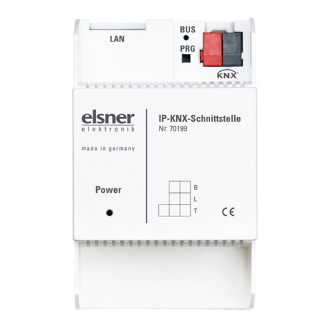
Elsner RF-B2-UP Guide

Installation and Adjustment
RF-B2-UP
Radio-button interface
Item number 60540
EN


1 Contents
Elsner Elektronik GmbH • Sohlengrund 16 • 75395 Ostelsheim • Germany
Button interface RF-B2-UP
Version: 03.11.2021 • Subject to technical changes. Errors excepted.
1. Safety and operating instructions ....................................................... 3
2. Description ........................................................................................... 3
3. Commissioning .................................................................................... 4
3.1. Creating and deleting wireless connections .......................................................... 4
3.1.1. Controls WS1 and WS1000 Color/Style/Connect ....................................... 4
3.1.2. XS MSG2-AP motor control device ............................................................. 4
3.1.3. Controls Solexa / Arexa / Lixa, ventilator WL305 / WL610 / WFL, RF relay, RF-
VM 5
3.1.4. Ventilation units WL400/WL800, WL-Z ........................................................ 6
3.1.5. Motor control devices RF-MSG, RF relay UP .............................................. 6
3.1.6. Control Solexa II ............................................................................................ 7
4. Operation ............................................................................................. 7
4.1. Pushbutton functions ............................................................................................... 7
4.1.1. Order of the ventilation levels ..................................................................... 8

2 Clarification of signs
This manual is amended periodically and will be brought into line with new software
releases. The change status (software version and date) can be found in the contents footer.
If you have a device with a later software version, please check
www.elsner-elektronik.de in the menu area "Service" to find out whether a more up-to-
date version of the manual is available.
Clarification of signs used in this manual
Safety advice.
Safety advice for working on electrical connections, components,
etc.
DANGER! ... indicates an immediately hazardous situation which will lead to
death or severe injuries if it is not avoided.
WARNING! ... indicates a potentially hazardous situation which may lead to
death or severe injuries if it is not avoided.
CAUTION! ... indicates a potentially hazardous situation which may lead to
trivial or minor injuries if it is not avoided.
ATTENTION! ... indicates a situation which may lead to damage to property if it is
not avoided.

3 Safety and operating instructions
Button interface RF-B2-UP • Version: 03.11.2021 • Technical changes and errors expected.
1. Safety and operating instructions
Installation, testing, operational start-up and troubleshooting should
only be performed by an authorised electrician.
CAUTION!
Live voltage!
There are unprotected live components inside the device.
• Inspect the device for damage before installation. Only put undamaged
devices into operation.
• Comply with the locally applicable directives, regulations and provisions for
electrical installation.
• Immediately take the device or system out of service and secure it against
unintentional switch-on if risk-free operation is no longer guaranteed.
Use the device exclusively for building automation and observe the operating
instructions. Improper use, modifications to the device or failure to observe the
operating instructions will invalidate any warranty or guarantee claims.
Operate the device only as a fixed-site installation, i.e. only in assembled condition and
after conclusion of all installation and operational start-up tasks, and only in the
surroundings designated for it.
Elsner Elektronik is not liable for any changes in norms and standards which may occur
after publication of these operating instructions.
For information on installation, maintenance, disposal, scope of
delivery and technical data, please refer to the installation
instructions.
2. Description
The Button interface RF-B2-UP features four connections for two double buttons
(up/down or on/off) and transfers the switching signals to the taught device by radio.
Suitable for the following devices:
• Control WS1 Color from version 1.597
• Controls WS1 Style and (KNX) WS1000 Style
• Control WS1000 Connect
• Control Solexa from version 3.6
• Control Solexa II from software version 1.0
• Control Arexa from version 3.7
• Ventilation units WL400 and WL800 from version 1.0
• Air supply unit WL-Z from version 1.0, WFL from version 2.0
• RF relay from version 2.0, RF-MSG, RF-VM
• F-Con radio units RF-HE-ST, RF-MSG-ST, RF-Relais-ST, RF-MSG(2)-DST,
RF-L PWM-ST, RF-L LED-ST, RF-L UN-ST, RF-L-DST 1-10 V, RF-L-DST DALI

4 Commissioning
Button interface RF-B2-UP • Version: 03.11.2021 • Technical changes and errors expected
3. Commissioning
3.1. Creating and deleting wireless connections
Each of the pushbuttons connected to input 1 and 2 controls one or several drives/devices.
3.1.1. Controls WS1 and WS1000 Color/Style/Connect
Learn:
1. Prepare control for learning:
•MenuSystem > Installation > Radio connection> Learning.
• Please also follow the instructions in the manual.
2. Teaching the pushbutton interface:
• Briefly press the PRG key 1 or 2 on the pushbutton interface once.
• The selected PRG key will not affect the configuration of the WS1000 Color/
WS1 Color.
3. Acknowledgement from the control system:
• Control signals "device taught".
Once the Button interface RF-B2-UP has been taught to know the control, you can
assign a name to the pushbutton interface in the menu System > Installation > Radio
connection > Status and assign drives and devices to pushbutton 1 and 2 ("channel" 1
and 2).
Deletion:
1. Deleting a radio connection:
• On the control, call up the menu item System > Installation > Radio
connection> Delete.
• Please also follow the instructions in the manual.
3.1.2. XS MSG2-AP motor control device
Teaching and deletion may only be carried out by a qualified
electrician (according to VDE 0100)!
Learn:
1. Prepare motor control device for learning:
(also see chapter "Radio connection motor control device - Remo 8" in the manual)
• Press the learning/deletion key of the motor control device briefly 3 times
until the left LED comes on.
• For the right channel, press the learning/deletion key of the motor control
device briefly 4 times until the right LED comes on.
2. Teaching the pushbutton interface:
• Press the PRG key 1 (for pushbutton 1) or 2 (for pushbutton 2) on the
pushbutton interface once briefly.

5 Commissioning
Button interface RF-B2-UP • Version: 03.11.2021 • Technical changes and errors expected.
The pushbutton is now configured to the channel of the motor control unit.
Deletion:
1. Prepare control for deletion:
(see also the chapter "Radio connection motor control device - Remo 8" in the man-
ual)
• Press the learning/deletion key of the motor control device briefly 3 times
until the left LED comes on.
• For the right channel, press the learning/deletion key of the motor control
device briefly 4 times until the right LED comes on.
2. Deleting the pushbutton interface:
• Press the PRG key 1 (for pushbutton 1) or 2 (for pushbutton 2) on the
pushbutton interface once for more than 3 seconds until the programming
LED comes on.
• Press the PRG once again for longer than 3 seconds until the programming
LED flashes (= ready for deletion)
• Press the PRG key once again briefly.
The wireless connection is deleted.
3.1.3. Controls Solexa / Arexa / Lixa, ventilator WL305 /
WL610 / WFL, RF relay, RF-VM
Teaching and deletion may only be carried out by a qualified
electrician (according to VDE 0100)!
Learn:
1. Prepare pushbutton interface for learning:
• Press the PRG key 1 (for pushbutton 1) or 2 (for pushbutton 2) on the
pushbutton interface once for more than 3 seconds until the programming
LED comes on (= ready for learning)
2. Teach controls, ventilators or relays:
• Press the programming button inside the device briefly a single time using
an insulated screwdriver.
The pushbutton is now taught for the device.
Deletion:
1. Prepare pushbutton interface for deletion:
• Press the PRG key 1 (for pushbutton 1) or 2 (for pushbutton 2) on the
pushbutton interface once for more than 3 seconds until the programming
LED comes on.
• Press the PRG once again for longer than 3 seconds until the programming
LED flashes (= ready for deletion)
2. Delete controls, ventilators or relays:
• Press the programming button inside the device briefly a single time using
an insulated screwdriver.

6 Commissioning
Button interface RF-B2-UP • Version: 03.11.2021 • Technical changes and errors expected
The wireless connection is deleted.
3.1.4. Ventilation units WL400/WL800, WL-Z
Teaching and deletion may only be carried out by a qualified
electrician (according to VDE 0100).
Learn:
5. Prepare pushbutton interface for learning:
• Press the PRG key 1 (for pushbutton 1) or 2 (for pushbutton 2) on the
pushbutton interface once for more than 3 seconds until the programming
LED comes on (= ready for learning)
6. Teach ventilation unit:
• Switch on the 230 V power supply to the fan and/or shut off the power
supply briefly if the unit is already supplied with power. The fan
automatically teaches itself after the mains voltage is applied.
Deletion:
1. Prepare pushbutton interface for deletion:
• Press the PRG key 1 (for pushbutton 1) or 2 (for pushbutton 2) on the
pushbutton interface once for more than 3 seconds until the programming
LED comes on.
• Press the PRG once again for longer than 3 seconds until the programming
LED flashes (= ready for deletion)
2. Deleting a ventilation unit:
• Switch on the 230 V power supply to the fan and/or shut off the power
supply briefly if the unit is already supplied with power. The radio
connection will be cleared automatically after the mains voltage is applied.
3.1.5. Motor control devices RF-MSG, RF relay UP
Teaching and deletion may only be carried out by a qualified
electrician (according to VDE 0100).
Learn:
1. Prepare pushbutton interface for learning:
• Press the PRG key 1 (for pushbutton 1) or 2 (for pushbutton 2) on the
pushbutton interface once for more than 3 seconds until the programming
LED comes on (= ready for learning)
2. Teach relay or motor control device:
• Switch on the voltage supply of the RF-MSG or RF relay UP. The motor
control unit automatically teaches itself 3 seconds after the mains voltage
is applied.

7 Operation
Button interface RF-B2-UP • Version: 03.11.2021 • Technical changes and errors expected.
Deletion:
1. Prepare pushbutton interface for deletion:
• Press the PRG key 1 (for pushbutton 1) or 2 (for pushbutton 2) on the
pushbutton interface once for more than 3 seconds until the programming
LED comes on.
• Press the PRG once again for longer than 3 seconds until the programming
LED flashes (= ready for deletion)
2. Deleting a relay or motor control device:
• Switch the voltage supply of the RF-MSG or RF relay UP off and then on
again. The radio connection will be cleared automatically 3 seconds after
the mains voltage is applied.
3.1.6. Control Solexa II
Learn:
1. Prepare control for learning:
•Menubase settings > LEA.
• Please also follow the instructions in the manual.
2. Teaching the pushbutton interface:
• Press the PRG key 1 (for pushbutton 1) or 2 (for pushbutton 2) on the
pushbutton interface once briefly.
The pushbutton is now taught for the control.
Deletion:
1. Deleting a radio connection:
• On the control, call up the menu item base settings > LEA > StAt > settings
key > SET key.
• Please also follow the instructions in the manual.
4. Operation
4.1. Pushbutton functions
Up/Down via the connected up/down double pushbutton
Integrated pushbutton automatics:
• Key pressed briefly = step operation
• Key pressed for a longer time = movement to final position
• Briefly pressing the opposite direction key = stop
On/Off via the connected double pushbutton (pushbutton 1 = on, pushbutton 2= off)
Dimming via the connected up/down double pushbutton
Integrated pushbutton automatics:
• "Up" briefly = ON with the last dimming value.
• "Up" long = brighter
•"Down"briefly=OFF

8 Operation
Button interface RF-B2-UP • Version: 03.11.2021 • Technical changes and errors expected
• "Down" long = darker
4.1.1. Order of the ventilation levels
Ventialtion units WL305/610 and WL400/800:
Exhaust air 8 – 7 – 6 – 5 – 4 – 3 – 1 – off– Circulation air 1 – 2 – 3 – 4 – 5 – 6 – 7 – 8


Elsner Elektronik GmbH Control and Automation Engineering
Sohlengrund 16
Germany Fax +49 (0) 70 33 / 30 945-20 www.elsner-elektronik.de
Technical support: +49 (0) 70 33 / 30 945-250
This manual suits for next models
1
Table of contents
Other Elsner Recording Equipment manuals
Popular Recording Equipment manuals by other brands
ITS Telecom
ITS Telecom 6520 Operation manual
Ingersoll-Rand
Ingersoll-Rand TRANE BCI-R Application guide
Extron electronics
Extron electronics RGB 580x user guide
Lectrosonics
Lectrosonics PDR quick start guide

Meyer Sound
Meyer Sound Matrix3 LX-300 Hardware reference guide
Network Electronics
Network Electronics Flashlink DLY-AES user manual
