Elson CBi Release note

CB Heat Interface Unit Manual
Wall Mounted Heat Interface Units for
Community Heating Systems
Installation & Servicing Instructions
IMPORTANT
Please read & understand these instructions along with the instructions for the heating
controller, unvented cylinder / thermal store before commencing installation.
Please leave this manual with the user for future reference.

Page 2
INTRODUCTION..................................................................3
GENERAL REQUIREMENTS..............................................3
PRODUCT SPECIFICATION...............................................3
PRODUCT FEATURES........................................................4
DIMENSIONS AND WEIGHT............................................12
INSTALLATION ................................................................13
WIRING..............................................................................16
WIRING DIAGRAMS.........................................................17
HYDRAULIC DIAGRAMS..................................................21
HYDRAULIC DIAGRAMS LEGEND..................................26
CONTROL STRATEGY......................................................27
MAJOR COMPONENTS...................................................29
COMMISSIONING.............................................................36
SERVICE............................................................................37
FAULT FINDING.................................................................38
SPARES..............................................................................39
SALES AND SUPPORT.....................................................44
CONTENTS

Page 3
The heating and hot water to your home are provided
by the CB heat interface unit and unvented cylinder or
thermal store package.
Heat is supplied to the CB heat interface unit from the
central boiler(s) installed elsewhere in the building. The
central boiler will provide heat to your CB unit for your
central heating and domestic hot water.
The CB heat interface unit is a heat only unit and works in
conjunction with an indirect domestic hot water cylinder or
thermal store to provide hot water to your taps. As such
you must read these instructions in conjunction with those
for the cylinder / thermal store.
The CB heat interface unit can be fitted within a cylinder
frame. The cylinder frame arrangement permits the
cylinder / thermal store to sit above a washing machine
or shelves for storage. This space saving design is
particularly advantageous for apartments with open plan
living areas, as this allows the washing machine to be
positioned in the airing cupboard (not detailed in these
instructions).
Alternatively the CB heat interface unit is suitable for wall
mounting and can be supplied with a first fix rail for ease
of installation. For wall mounted versions an optional set of
casings is available on request.
The CB unit is supplied complete with all the necessary
safety and control devices needed to allow connection
to the community heating system and the apartment’s
central heating system.
The CB heat interface unit can provide space heating via a
radiator or underfloor heating system.
This appliance complies with the requirements of the CE
marking directive.
The following instructions are offered as a guide to
installation which must be carried out by a competent
plumbing and electrical installer in accordance with
Building, Electrical and Water Regulations.
NOTE: Prior to installation, the unit should be stored in an
area free from excessive dampness or humidity.
IMPORTANT:
THIS APPLIANCE CAN BE USED BY CHILDREN
AGED FROM 8 YEARS AND ABOVE AND
PERSONS WITH REDUCED PHYSICAL SENSORY
OR MENTAL CAPABILITIES OR LACK OF
EXPERIENCE AND KNOWLEDGE IF THEY HAVE
BEEN GIVEN SUPERVISORY OR INSTRUCTION
CONCERNING USE OF THE APPLIANCE IN A
SAFE WAY AND UNDERSTAND THE HAZARDS
INVOLVED. CHILDREN SHALL NOT PLAY
WITH THE APPLIANCE. CLEANING AND USER
MAINTENANCE SHALL NOT BE MADE BY
CHILDREN WITHOUT SUPERVISION.
INTRODUCTION
GENERAL REQUIREMENTS
Maximum Working Pressure:
Primary Side (Community / District Heating): 10 bar g
Secondary Side (Apartment Heating): 3 bar g
Maximum Working Temperature:
Primary Side (Community / District Heating): 90 deg C
Secondary Side (Apartment Heating): 85 deg C
Primary Side Pressure drop 30 kPa
As previously stated, the CB heat interface unit is a versatile
unit suitable for wall mounting or fitting within a purpose
made frame.
The CB heat interface unit includes the following
components:
- an apartment central heating pump,
- pump isolation valves,
- steel central heating manifold with built-in central
heating bypass,
- standard S plan or S plan plus control system
- either 2 or 3 No. two port motorized zone valves,
- an 8 litre sealed system expansion vessel,
- central heating pressure relief valve with tundish,
- Automatic air vent with anti-suction valve and shut
off valve for ease of maintenance,
- brazed stainless steel plate heat-exchanger to provide a
pressure break between the community (district) heating
system and the apartment’s central heating system,
- provision for a heat meter in the apartment’s system,
- community (district) heating 2-port pressure independent
balancing and control valve,
- district heating in-line strainer,
- all mounted on a powder coated steel back plate.
Filling Loop and Pressure Gauge
The system filling loop and associated pressure gauge
are supplied as part of the cylinder / thermal store primary
pipework kit, as these need to be installed adjacent to both
the central heating system and cold water mains pipework.
Where the cylinder / thermal store is supplied by a third party,
these components will be deemed outside the Elson scope of
supply / responsibility.
PRODUCT SPECIFICATION
Safety Valve
WATER MAY DRIP FROM THE DISCHARGE PIPE
OF THE PRESSURE RELIEF VALVE. THE TUNDISH
PROVIDED ALLOWS THE DISCHARGE PIPE TO
ALWAYS BE OPEN TO THE ATMOSPHERE. AS PART
OF THE MAINTENANCE REGIME FOR THE PRODUCT
REGULARLY OPERATE THE SAFETY VALVE TO ENSURE
IT IS NOT BLOCKED.

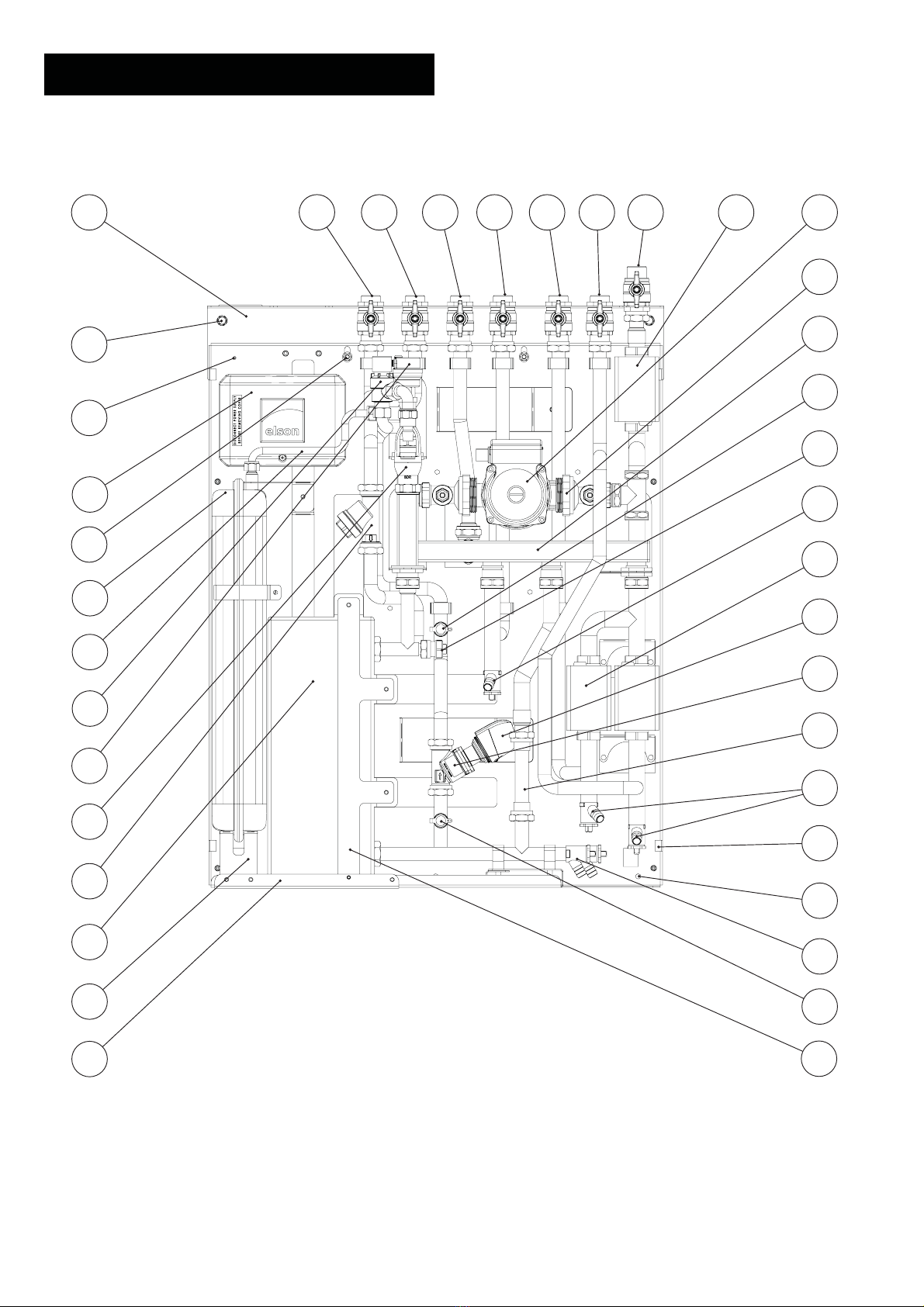
PRODUCT FEATURES
Fig 1 Product Features and Components for the CB-1Z (Single Heating Zone)
1
2
3
4
5
6
7
8
9
10
11
12
13 14
15
16
17
18
19
20
21
22
23
24
25
2627
2829
30
31
32
Page 4

(1) First fix rail bracket
(2) 4 No. Fixing holes for first fix rail (7mm)
(3) Earth stud (M4)
(4) Wiring Centre
(5) HIU mounting studs (M6) x 2 on 1st fix rail
(6) 8 litre expansion vessel with 3/8”bsp system connection
(7) Expansion vessel pipe
(8) 15mm central heating system safety valve 3 bar g
(9) 3/8” automatic air vent complete with shut off valve and anti-suction valve
(10) 15mm x 22mm compression tundish
(11) Brazed stainless steel plate heat exchanger with EPP moulded insulation cover
(12) Expansion vessel support bracket
(13) Plate heat exchanger support rail
(14) Plate heat exchanger support bracket
(15) Unit drain valves (Primary and secondary circuits)
(16) Wall mounting bottom fixing holes (3 No.)
(17) Frame fixing slots
(18) Apartment heating zone drain valve
(19) Volume flow meter (for heat meter) stool piece 3/4”bsp x 110mm centres EN1434
(20) Apartment heating 2 port zone valve
(21) Common central heating return drain valve
(22) Position of 1/2”bsp heat meter flow sensor pocket (supplied by heat meter company)
(23) Elson central heating system manifold
(24) Pump isolation unions
(25 Central heating pump
(26) HWS primary 2 port zone valve
(27) HWS primary flow connection - 3/4”bsp male
(28) Central heating flow (zone 1) connection - 3/4”bsp male
(29) Common central heating return connection - 3/4”bsp male
(30) HWS primary return connection - 3/4”bsp male
(31) Community (district) heating return - 3/4”bsp male
(32) Community (district) heating flow - 3/4”bsp male
PRODUCT FEATURES
Page 5

PRODUCT FEATURES
Fig 2 Product Features and Components for the CB-1Z-DC (Single Heating Zone with District Control Valve)
1
2
3
4
5
6
7
8
9
10
11
12
13
14 15
16
17
18
19
20
21
22
23
24
25
26
27
28
29
30
3132
3334
35
36
37
Page 6

(1) First fix rail bracket
(2) 4 No. Fixing holes for first fix rail (7mm)
(3) Earth stud (M4)
(4) Wiring Centre
(5) HIU mounting studs (M6) x 2 on first fix rail
(6) 8 litre expansion vessel with 3/8”bsp system connection
(7) Expansion vessel pipe
(8) 15mm central heating system safety valve 3 bar g
(9) 3/8” automatic air vent complete with shut off valve and anti-suction valve
(10) 15mm x 22mm compression tundish
(11) 3/4”bsp male Y strainer
(12) Brazed stainless steel plate heat exchanger with EPP moulded insulation cover
(13) Expansion vessel support bracket
(14) Plate heat exchanger support rail
(15) Plate heat exchanger support bracket
(16) Test point (red) to measure the pressure drop across the district control valve
(17) Unit drain valves (Primary and secondary circuits)
(18) Wall mounting bottom fixing holes (3 No.)
(19) Frame fixing slots
(20) Apartment heating zone drain valve
(21) Volume flow meter (for heat meter) stool piece 3/4”bsp x 110mm centres EN1434
(22) DN 15 Frese Optima Compact pressure independent balancing and control valve
(23) 230V on/off thermo actuator
(24) Apartment heating 2 port zone valve
(25) Common central heating return drain valve
(26) Position of 1/2”bsp heat meter flow sensor pocket (supplied by heat meter company)
(27) Test point (blue) to measure the pressure drop across the district control valve
(28) Elson central heating system manifold
(29) Pump isolation unions
(30) Central heating pump
(31) HWS primary 2 port zone valve
(32) HWS primary flow connection - 3/4”bsp male
(33) Central heating flow (zone 1) connection - 3/4”bsp male
(34) Common central heating return connection - 3/4”bsp male
(35) HWS primary return connection - 3/4”bsp male
(36) Community (district) heating return - 3/4”bsp male
(37) Community (district) heating flow - 3/4”bsp male
PRODUCT FEATURES
Page 7

PRODUCT FEATURES
Fig 3 Product Features and Components for the CB-2Z (Two Heating Zones)
1
2
3
4
5
6
7
8
9
10
11
12
13 14
15
16
17
18
19
20
21
22
23
24
25
2627
29
30
31
32
33 28
Page 8

(1) First fix rail bracket
(2) 4 No. Fixing holes for first fix rail (7mm)
(3) Earth stud (M4)
(4) Wiring Centre
(5) HIU mounting studs (M6) x 2 on 1st fix rail
(6) 8 litre expansion vessel with 3/8”bsp system connection
(7) Expansion vessel pipe
(8) 15mm central heating system safety valve 3 bar g
(9) 3/8” automatic air vent complete with shut off valve and anti-suction valve
(10) 15mm x 22mm compression tundish
(11) Brazed stainless steel plate heat exchanger with EPP moulded insulation cover
(12) Expansion vessel support bracket
(13) Plate heat exchanger support rail
(14) Plate heat exchanger support bracket
(15) Unit drain valves (primary and secondary circuits)
(16) Wall mounting bottom fixing holes (3 No.)
(17) Frame fixing slots
(18) Apartment heating zones drain valve
(19) Volume flow meter (for heat meter) stool piece 3/4”bsp x 110mm centres EN1434
(20) Apartment heating 2 port zone valves
(21) Common central heating return drain valve
(22) Position of 1/2”bsp heat meter flow sensor pocket (supplied by heat meter company)
(23) Elson central heating system manifold
(24) Pump isolation unions
(25) Central heating pump
(26) HWS primary 2 port zone valve
(27) HWS primary flow connection - 3/4”bsp male
(28) Central heating flow (zone 2) connection - 3/4”bsp male
(29) Central heating flow (zone 1) connection - 3/4”bsp male
(30) Common central heating return connection - 3/4”bsp male
(31) HWS primary return connection - 3/4”bsp male
(32) Community (district) heating return - 3/4”bsp male
(33) Community (district) heating flow - 3/4”bsp male
PRODUCT FEATURES
Page 9
PRODUCT FEATURES
Fig 4 Product Features and Components for the CB-2Z-DC (Two Heating Zones with District Control Valve)
1
2
3
4
5
6
7
8
9
10
11
12
13
14 15
16
17
18
19
20
21
22
23
24
25
26
27
28
29
30
3132
34
35
36
37
38 33
Page 10

(1) First fix rail bracket
(2) 4 No. Fixing holes for first fix rail (7mm)
(3) Earth stud (M4)
(4) Wiring Centre
(5) HIU mounting studs (M6) x 2 on first fix rail
(6) 8 litre expansion vessel with 3/8”bsp system connection
(7) Expansion vessel pipe
(8) 15mm central heating system safety valve 3 bar g
(9) 3/8” automatic air vent complete with shut off valve and anti-suction valve
(10) 15mm x 22mm compression tundish
(11) 3/4”bsp male Y strainer
(12) Brazed stainless steel plate heat exchanger with EPP moulded insulation cover
(13) Expansion vessel support bracket
(14) Plate heat exchanger support rail
(15) Plate heat exchanger support bracket
(16) Test point (red) to measure the pressure drop across the district control valve
(17) Unit drain valves (primary and secondary circuits)
(18) Wall mounting bottom fixing holes (3 No.)
(19) Frame fixing slots
(20) Apartment heating zones drain valve
(21) Volume flow meter (for heat meter) stool piece 3/4”bsp x 110mm centres EN1434
(22) DN 15 Frese Optima Compact pressure independent balancing and control valve
(23) 230V on/off thermo actuator
(24) Apartment heating 2 port zone valves
(25) Common central heating return drain valve
(26) Position of 1/2”bsp heat meter flow sensor pocket (supplied by heat meter company)
(27) Test point (blue) to measure the pressure drop across the district control valve
(28) Elson central heating system manifold
(29) Pump isolation unions
(30) Central heating pump
(31) HWS primary 2 port zone valve
(32) HWS primary flow connection - 3/4”bsp male
(33) Central heating flow (zone 2) connection - 3/4”bsp male
(34) Central heating flow (zone 1) connection - 3/4”bsp male
(35) Common central heating return connection - 3/4”bsp male
(36) HWS primary return connection - 3/4”bsp male
(37) Community (district) heating return - 3/4”bsp male
(38) Community (district) heating flow - 3/4”bsp male
PRODUCT FEATURES
Page 11

Page 12
DIMENSIONS AND WEIGHT
Fig 5 CB-1Z and CB-1Z-DC Heat Interface Unit - 1 Heating Zone
Fig 6 CB-2Z and CB-2Z-DC Heat Interface Unit - 2 Heating Zones
(1) Community (district) heating flow - 3/4”bsp male
(2) Community (district) heating return - 3/4”bsp male
(3) HWS primary return connection - 3/4”bsp male
(4) Common central heating return connection - 3/4”bsp male
(5) Central heating flow (zone 1) connection - 3/4”bsp male
(6) Central heating flow (zone 2) connection - 3/4”bsp male
(7) HWS primary flow connection - 3/4”bsp male
(1) Community (district) heating flow - 3/4”bsp male
(2) Community (district) heating return - 3/4”bsp male
(3) HWS primary return connection - 3/4”bsp male
(4) Common central heating return connection - 3/4”bsp male
(5) Central heating flow (zone 1) connection - 3/4”bsp male
(6) N/A
(7) HWS primary flow connection - 3/4”bsp male
Unit Dry Weight (kg)
6 valve 1st fix rail 2.5
CB-1Z 25.0
CB-1Z-DC 26.0
Unit Dry Weight (kg)
7 valve 1st fix rail 2.8
CB-2Z 27.0
CB-2Z-DC 28.0
CB-1Z-DC unit detailed.
CB-2Z-DC unit detailed.
Note: All dimensions are for reference only.
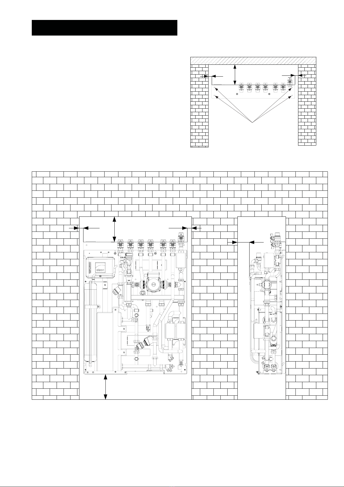
Page 13
INSTALLATION
Access
The CB unit must be vertically mounted, either on a
supporting wall or within the cylinder frame provided for the
frame mounted variant. Although location is not critical, the
following points should be considered:
• Avoid siting where extreme cold temperatures will
be experienced. All exposed pipe work should be
insulated.
• The discharge pipework from the safety valves
must have minimum fall of 1:200 from the unit and
terminate in a safe and visible position.
• Access to associated controls and components
must be available to provide for the servicing and
maintenance of the system. Please refer to Fig 7 and
Fig 8 for minimum clearance requirements.
• Ensure the first fix rail is installed horizontally, check using
a spirit level.
Fig 8 Minimum Clearances
Please note that the clearance dimension detailed
above are for guidance. In installations where
available space to site the unit is less than these
recommendations please seek advice from Elson
Technical on 0844 335 8819.
Fig 7 Fitting the first fix rail
Note: CB-2Z-DC detailed.
Note: 7 valve rail detailed.
Fixing points
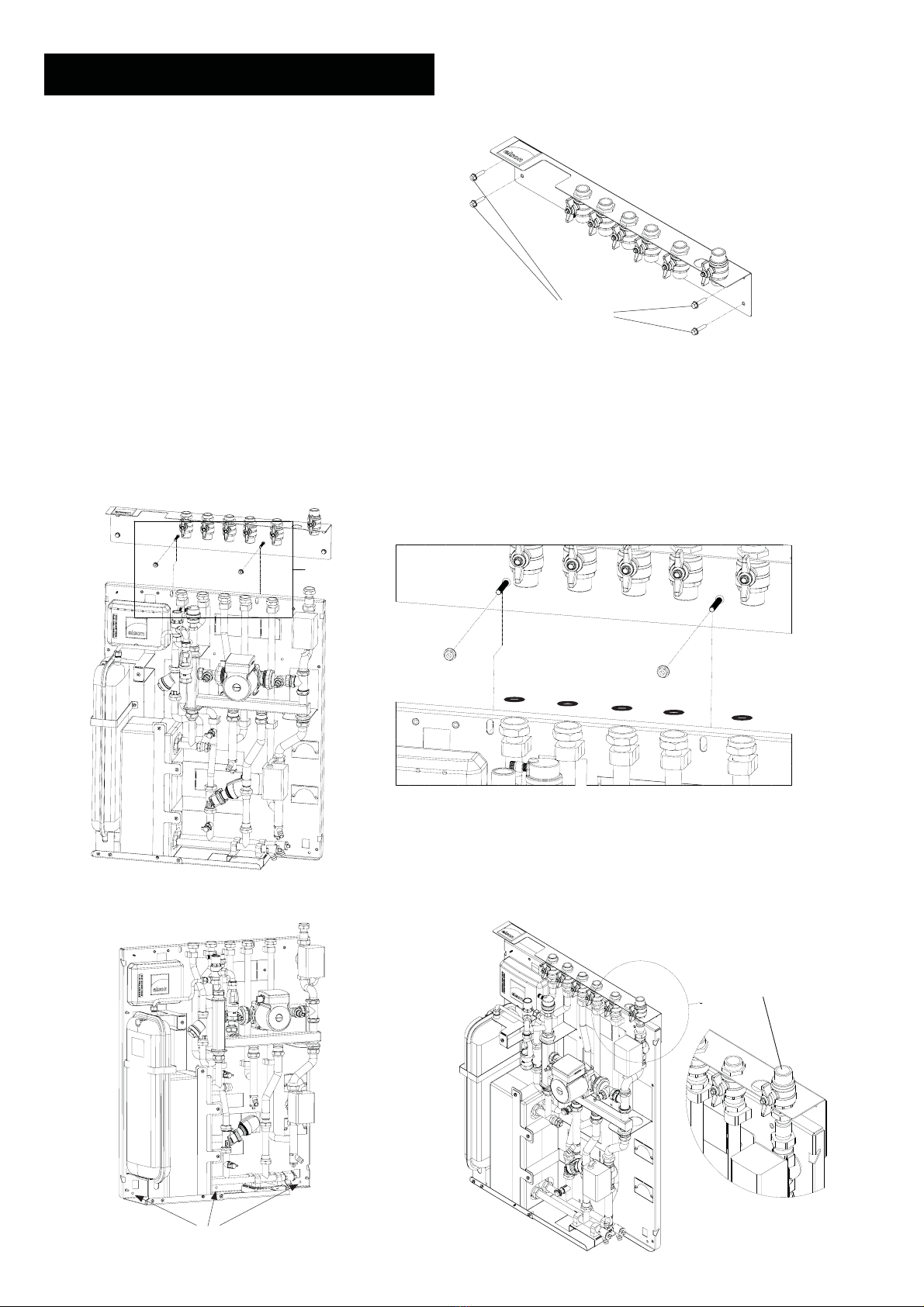
Page 14
INSTALLATION
$
'(7$,/$
Fig 10. CB Heat Interface Unit - Mounting on the 1st fix rail
Fig 11 CB Heat Interface Unit - Bottom Support Fixing
Points
Bottom Fixing Points
Wall Fixing
The CB unit can be supplied with a first fix rail for ease of
installation. The rail allows the plumber to pipe up and test
the pipework to and from the heat interface unit without
the need to have the heat interface unit on site.
• Ensure that the access requirements detailed in
Fig 7 and Fig 8 have been met.
• Ensure the surface to be used will sustain the weight
of the unit when full of water.
• Fix the 1st fix rail to the wall using suitable fixings and
ensure the rail is level (Fig. 9).
• Slide the two studs provided on the 1st fix rail through
the slotted holes in the CB unit back plate and secure
loosely with the M6 nuts provided (Fig 10).
• Insert the washers supplied onto the tops of the pipe
faces on the CB unit and slide the CB unit upwards
until the washers come in contact with the isolation
valves on the 1st fix rail and tighten nuts.
• Mark out and drill the bottom fixing points and use
suitable fixings for the mounting surface (see Fig 11).
CB-1Z-DC Single heating zone unit detailed.
$
'(7$,/$
Fig 12 CB Heat Interface Unit - 1st fix rail isolation
valves IMPORTANT
Ensure the HWS primary
flow isolation valve is above
the rail bracket. All other
isolation valves should be
below the rail
Fig 9. First fix rail mounting details
Suitable
fixings
(not supplied)
CB-1Z-DC Single heating zone unit detailed.

INSTALLATION
TRVs, Room Thermostats and Automatic Bypass:
The room thermostat should be installed in the coldest
room in the house where the only heat source is a radiator
without TRV. The radiator should be fitted with lock
shield valves to avoid it being inadvertently isolated. It will
then act as a system bypass and heat dissipater for the
system.
Access for Servicing:
When installing the equipment within a confined space
/ cupboard consideration should be given to future
servicing and maintenance of the CB unit. Therefore
adequate access should be given to pumps, valves and
accessories. Please see Fig 7 and Fig 8.
System Filling:
The heating system filling loop is intended for temporary
connection to the system only. When this is not in use for
filling / topping up, the filling loop must be disconnected in
accordance with local water bylaws.
System Venting:
Automatic air vents should be used where practicable at
system high points.
In the case of pipework at high level which is not
accessible (i.e. on district systems within apartments and
similar) a line size automatic separator should be fitted.
Pipe Jointing and Cleaning:
All joints which are to be soldered should be made using a
flux that is sparingly applied and any residue to be flushed
out of the system before commissioning using a chemical
cleanser if necessary. All as per British Gas specification
for domestic wet central heating systems.
Pipework Insulation:
Elson system packages are supplied without pipe
insulation to allow the installer to ensure all joints are still
sound after installation. It is recommended that these
pipes are insulated.
District heating flow and return pipes should be insulated
to avoid stray heat losses in the apartment.
All pipes in unheated areas must be insulated in
accordance with local and national regulations.
Flushing bypass arrangement:
It is recommended that a flushing bypass arrangement is
installed to allow the CB heat interface unit to be isolated
from the district heating system during flushing and filling
of the distribution network.
District heating piping arrangement:
Where the CB unit is fitted with a two port on/off district
heating control valve, all branches within the distribution
pipework should be fitted with a reduced flow bypass
valve to ensure water flows through these pipes at all
times. It is recommended that this valve is sized and set to
pass 5% of the design flow rate for each branch. Details
of this arrangement are shown in Fig 24.
Two channel programmable room thermostat:
The CB heat interface unit can be supplied with a Danfoss
TP9000 2 channel controller (available as an accessory).
The controller has an in built room thermostat to control
one heating zone and also comes with a separate room
sensor should you wish to install the controller in a
cupboard or the kitchen for example.
On systems where there are two heating zones, an
additional programmable room thermostat, such as the
TP5000 is required (available as an accessory).
Treatment of water in the central heating system
All re-circulatory water systems will be subject to corrosion
unless they are flushed and an appropriate water
treatment is applied. To prevent this, follow the guidelines
given in BS 7593 ‘Treatment of Water in Domestic Hot
Water Central Heating Systems’ and the treatment
manufacturer’s instructions.
Treatment must involve the use of a proprietary cleanser,
such as Sentinel X300 or X400, or Fernox F3 and an
inhibitor such as Sentinel X100 or Fernox MB-1.
Full instructions are supplied with the products. For further
information contact Sentinel or Fernox.
Failure to flush and add inhibitor to the system will
invalidate the appliance warranty.
It is important to check the inhibitor concentration after
installation, system modification and at every service in
accordance with the inhibitor manufacturer’s instructions.
(Test kits are available from inhibitor stockists.)
For information or advice regarding any of the above
contact Technical Enquiries 0844 335 8819.
Earth Bonding
Ensure the installation is earth bonded in accordance with
BS EN 7671:2008.
Page 15

WIRING
Wiring
The CB heat interface unit is fitted with a pre-wired wiring
centre for ease of installation. There is an additional entry
point available on the right hand side of the wiring centre for
the mains cable and the cylinder / thermal store thermostat
cable. This is detailed in Fig 13.
Electrical isolation
The power supply to the CB unit should come via a double
poled isolation switched fused spur with contact separation
of at least 3mm fused at 3 Amps.
Cable entry point Cable bar clamp Clamp fixing points
Fig 13 Wiring centre
Fig 14 District Heating flow pipe thermostat
When the district heating system has a set back
temperature regime a district heating flow pipe thermostat
can be supplied to prevent the thermal store from being
charged during the set back temperature periods.
Main district flow pipe
Spring clip
District flow pipe
thermostat
3 core cable
IMPORTANT
The pipe thermostat must be fitted to the main flow pipe prior
to the flow pipe leg entering the apartment. This will ensure
the thermostat witnesses the temperature within the district
heating flow at all times.
The thermostat is set around a mean temperature of
70 deg C and wired across terminals 1 and 3 to make
contact on temperature rise. Thus allowing the cylinder to be
charged during district heating boost periods.
Fig 15 Fitting the thermostat to the flow pipe
ALL WIRING MUST BE IN ACCORDANCE WITH IEE &
BUILDING REGULATIONS.
A switch (having contact separation of at least 3mm in all
poles) must be incorporated in the fixed wiring as a means of
disconnecting the mains supply.
The heating system must be appropriately fused. A fuse
rated at no more than 3 amps should be installed.
Earth terminals, where provided, are for earth continuity
purposes only. All earth conductors inside the programmer
and room thermostat must be appropriately sleeved.
The zone valves are Class I devices and must be
connected to a suitable earth.
The unit should be earthed throughout and cross bonded.
Page 16
IMPORTANT
Please note that the blue neutral
wire MUST be identified with a
brown sleeve to indicate that it is
used as a live cable.

WIRING DIAGRAM
4
6
Not Used
3
10
2
4
10
2
71
2
3
4
5
6
7
8
9
10
1
6
8
Mains supply
Fused @ 3amp
240 volt (by
others)
N
L
Brown
Blue
Grey
Orange
Green/Yellow
V4043H1056
Zone valve
Hot water
Brown
Blue
Grey
Orange
Green/Yellow
V4043H1056
Zone valve
Central heating
Zone 1
L
N
1
3
4
Programmer
TP9000MA
3
2
1
E
Not Used
HTG
HWS
11
12
13
14
15
16
N N N
N
N
N
N
Wiring
Centre
Green/Yellow
Orange
Grey
Blue
Brown
73
1
8
2
5
6
Room
Sensor
11 L
E
N
District Valve
11
E
N
Pump
L
N
N
Coral Aquanox
Thermostat
District Flow
Temperature
Thermostat
##
## Note:
Remove link when
district heating flow
thermostat is fitted.
Fig 16 Wiring diagram for CB-1Z and CB-1Z-DC heat interface unit with 1 heating zone, an Elson Coral Aquanox thermal store and a district
flow temperature thermostat
Page 17

WIRING DIAGRAM
4
6
Not Used
3
10
2
4
10
2
71
2
3
4
5
6
7
8
9
10
1
6
8
15
11
N
2
3
Mains supply
Fused @ 3amp
240 volt (by
others)
N
L
TP5000M Si
Programmable
Room thermostat
Zone 2
Brown
Blue
Grey
Orange
Green/Yellow
V4043H1056
Zone valve
Hot water
Brown
Blue
Grey
Orange
Green/Yellow
V4043H1056
Zone valve
Central heating
Zone 1
L
N
1
3
4
Programmer
TP9000MA
3
2
1
Coral Aquanox
Thermostat
E
Not Used
L
E
N
District Valve
11
E
N
Pump
L
HTG
HWS
11
12
13
14
15
16
N N N
N
N
N
N
N
N
N
Wiring
Centre
Green/Yellow
Orange
Grey
Blue
Brown
10
3
15
Brown
Blue
Grey
Orange
Green/Yellow
V4043H1056
Zone valve
Central heating
Zone 2
N
5
6
Room
Sensor
3
L
3
73
1District Flow
Temperature
Thermostat
8
2
##
## Note:
Remove link when
district heating flow
thermostat is fitted.
Fig 17 Wiring diagram for CB-2Z and CB-2Z-DC heat interface unit with 2 heating zones, an Elson Coral Aquanox thermal store and a district
flow temperature thermostat
Page 18

WIRING DIAGRAM
Fig 18 Wiring diagram for CB-1Z and CB-1Z-DC heat interface unit with 1 heating zone and a Megaflo eco unvented cylinder
4
6
Not Used
3
10
2
4
10
2
71
2
3
4
5
6
7
8
9
10
1
6
8
Mains supply
Fused @ 3amp
240 volt (by
others)
N
L
Brown
Blue
Grey
Orange
Green/Yellow
V4043H1056
Zone valve
Hot water
Brown
Blue
Grey
Orange
Green/Yellow
V4043H1056
Zone valve
Central heating
Zone 1
L
N
1
3
4
Programmer
TP9000MA
3
2
1
E
Not Used
HTG
HWS
11
12
13
14
15
16
N N N
N
N
N
N
Wiring
Centre
Green/Yellow
Orange
Grey
Blue
Brown
5
6
Room
Sensor
11 L
E
N
District Valve
11
E
N
Pump
L
N
N
Megaflo cylinder
Thermostat
##
## Note:
Remove link when
district heating flow
thermostat is fitted.
Page 19

WIRING DIAGRAM
4
6
Not Used
3
10
2
4
10
2
71
2
3
4
5
6
7
8
9
10
1
6
8
15
11
N
2
3
Mains supply
Fused @ 3amp
240 volt (by
others)
N
L
TP5000M Si
Programmable
Room thermostat
Zone 2
Brown
Blue
Grey
Orange
Green/Yellow
V4043H1056
Zone valve
Hot water
Brown
Blue
Grey
Orange
Green/Yellow
V4043H1056
Zone valve
Central heating
Zone 1
L
N
1
3
4
Programmer
TP9000MA
3
2
1
Megaflo cylinder
Thermostat
E
Not Used
L
E
N
District Valve
11
E
N
Pump
L
HTG
HWS
11
12
13
14
15
16
N N N
N
N
N
N
N
N
N
Wiring
Centre
Green/Yellow
Orange
Grey
Blue
Brown
10
3
15
Brown
Blue
Grey
Orange
Green/Yellow
V4043H1056
Zone valve
Central heating
Zone 2
N
5
6
Room
Sensor
3
L
3
##
## Note:
Remove link when
district heating flow
thermostat is fitted.
Fig 19 Wiring diagram for CB-2Z and CB-2Z-DC heat interface unit with 2 heating zones and a Megaflo eco unvented cylinder
Page 20
This manual suits for next models
1
Table of contents


