KEPCO MMI-7 Series User manual

1
MMI-7xx Series
MMI-750T-HB, MMI-750T,
MMI-750, MMI-720
Installation Instruction
MMI-7xx Series ............................................................................................................................................ 1
1.0 Environmental Considerations ............................................................................................................ 1
2.0 Mounting Instructions ......................................................................................................................... 1
3.0 Power Connections.............................................................................................................................. 2
4.0 Communications Connections............................................................................................................. 6
5.0 Dip Switch Settings............................................................................................................................. 9
6.0 MMI Indicator Lights.......................................................................................................................... 9
7.0 Other Hardware Considerations .......................................................................................................... 9
8.0 Trouble Shooting............................................................................................................................... 10
9.0 Specifications .................................................................................................................................... 11
1.0 Environmental Considerations
See Specifications for environmental constraints.
Location The MMI Series is designed for use in a factory environment. It is designed to operate
from 32 to 113 °F (0 to 45 °C) temperatures, as found in most industrial environments. It
may not be suitable for use in certain outdoor applications. Please consult the factory for
advised usage in outdoor applications.
NEMA
Rating The MMI Series front bezel is NEMA 4 rated. When installed properly in a NEMA 4
panel, the NEMA 4 rating of the panel is not compromised. This means that fluids do not
enter the panel through the MMI series panel during wash downs.
Do not operate the unit in areas subject to explosion hazards due to flammable gases,
vapors or dusts.
The unit should not be installed where fast temperature variations and/or high humidity are
present. This causes condensation of water in the device.
Avoid installing units in environments where severe mechanical vibration or shocks are
present.
Vibration endurance: 10 to 25 Hz (X,Y,Z direction 2G 30 minutes)
2.0 Mounting Instructions
2.1 LOCATION CONSIDERATIONS
Care should be taken when locating equipment behind the unit to ensure that AC power wiring, PLC
output modules, contactors, starters and relays, and any other source of electrical interference are located
away from the back of the unit.
Particular note should be taken to the position of variable speed drives and switching power supplies.
Their input and load cables should be screened to a central star earth point.

2
2.2 Making a NEMA-4 Mounting
Panel
Details The unit can be mounted into panels with a depth of 4”(105mm). It is recommended that
the unit be mounted on the front panel of a steel enclosure, through an appropriate
opening*. Allow a clearance of 1”(25mm) around the sides of the unit for mounting
hardware. Allow clearance for cable connections to the back of the unit. Unit depth may
vary according to cable type used. Typically, plan a depth to accommodate at least
3”(105mm) behind the panel.
Note: Deburr and clean cutout before beginning installation.
*Cutout dimensions:
7.56 [192]
5.43
[138]
MMI-720 / MMI-750 / MMI-750T / MMI-750T-HB
7.56"(192mm) W x 5.43"(138mm) H
NEMA-4
Mounting Put the unit through the panel cut out. Slide the clamps into the 4 or 6 holes provided
around the case. Tighten the clamping screws in an even pattern until the unit is secured in
the panel.
Caution! Do not over tighten mounting clamps!
Note:
Specifications To seal to NEMA-4 specifications, all supplied mounting clamps must be used and
panel must not flex more than 0.010”.
3.0 Power Connections
Make sure that all local and national electrical standards are met when the installing the unit. Contact your
local authorities to determine which codes apply.
3.1 POWER REQUIREMENTS
Power The MMI can be powered by DC power only. The specified voltage range is
+22 to 25 Volts DC. This insures compatibility with most controller DC
systems.
The power conditioning circuitry inside the unit is accomplished by a
switching power supply. The peak starting current can be as high as 700mA.
Fusing
Requirements It is recommended that all input power lines be protected from incorrect
wiring or product failure by a 2 Amp fuse or a breaker.
Note: If the display does not come on within 2 seconds of power up, remove
power. An internal fuse prevents damage if the polarity of the DC power is
incorrect. Check wiring to insure proper connections and try to power up
again.
Panel Mounting
clamp, 4or 6 places
Panel

3
Warning!
High Voltage Connecting high voltages or AC power mains to the DC input makes the unit
unusable and may create a hazard to personnel. Such a failure could result in
serious personal injury, loss of life and or equipment damage.
DC voltage sources should provide proper isolation from main AC power
and similar hazards.
Supply
Voltage
Condition
Do not power the MMI and inductive DC loads, or input circuitry to the
controller, with the same power supply.
Note: The 24 VDC output from some controllers may not have enough
current to power the MMI.
Wire Routing Wire lengths should be minimized.
Wires should be run in pairs with a neutral or common paired with a hot or
signal line.
Always use shielded cable to prevent unwanted electrical interference.
If wiring is to be exposed to lightning or surges, use appropriate surge
suppression devices.
Keep AC, high energy, and rapidly switching DC wiring separate from
signal wires by at least 8 inches. If signal wires must cross AC power, cross
at right angles.
Equip ungrounded DC supplies with a resistor and capacitor in parallel to
earth ground. This provides a path for static and high frequency dissipation.
Typical values to use are 1MOhm and 4700pF.
Electrical
Environment The MMI Series has been tested to conform to European CE requirements.
The circuitry is designed to resist the effects of electrical noise. This does not
guarantee noise immunity in severe cases. Proper wire routing and
grounding insures proper operation. The MMI Series is also UL certified.
Warning!
Emergency
Stop
A Hard-wired EMERGENCY STOP should be fitted in any system using an
MMI to comply with ICS Safety Recommendations.
Grounding
Requirements Chassis ground must be used. DC ground is not directly coupled to Earth
ground internally. It is preferable not to ground DC negative return to
chassis ground. Poor site earths can introduce noise into a system. If
necessary, an earth connection should be made from the power supply
return point to the central star earth point.
Ground conductors should be as short and as large in diameter as possible.
The conductors must always be large enough to carry the maximum short
circuit current of the path being considered. Ground conductors should be
connected to a tree from a central star earth ground point. This ensures that
no ground conductor carries current from any other branch.
CE
Requirements To make an MMI comply with EMC directives, and to reduce susceptibility
to electrical interference, a separate #14 AWG ground wire should be taken
to the chassis ground terminal of the power connector. This ground
connection should be run directly to the central star earth connection point
(as recommended in most Installation Instructions).
Use a ferrite core on the power wiring to reduce radiated emissions from the
DC power lines. It is recommended to use a 140Ohm@100MHz ferrite core
with the DC power lines looped through the core once. Position the ferrite
core less than 1” away from the DC power connection points on the back of
the MMI.
140 Ohm @ 100MHz ferrite

4
3.2 POWER CONNECTION
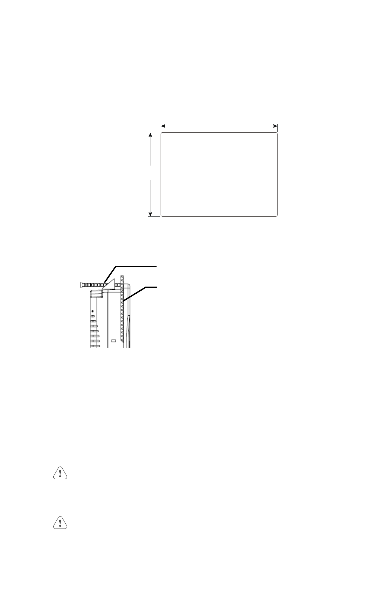
Connection +24 VDC Wiring Diagrams
Use 18 AWG wire to connect positive DC line to the +24V terminal and the
DC ground to the 0V terminal. See text above about FG (Chassis Ground).
Terminal Plug: To make a connection, strip about 3/8” of insulation off the
end of the wire, turn the connector screw counterclockwise until the gap is
wide open. Insert the wire all the way in, and turn the screw clockwise until
it’s tight.
+24V 0V F
G
3.3 SAFETY GUIDELINES
This section presents recommended installation practices, and procedures. Since no two applications are
identical, these recommendations should be considered as guidelines.
Hardware
Considerations WARNING!
The system designer should be aware that devices in Controller systems could fail
and thereby create an unsafe condition. Furthermore, electrical interference in an
operator interface, such as an MMI, can lead to equipment start-up, which could
result in property damage and/or physical injury to the equipment operator.
If you, or your company, use any programmable control systems that require an
operator or attendant, you should be aware that this potential safety hazard exists and
take appropriate precautions. Although the specific design steps depend on your
particular application, the following precautions generally apply to installation of
solid-state programmable control devices. In addition, these precautions conform to
the guidelines for installation of Controllers as recommended in the NEMA ICS 3-
304 Control Standards.
Programming
Considerations To conform with ICS Safety Recommendations, checks should be placed in the
controller to ensure that all writable registers that control critical parts of plant or
machinery have limit checks built into the program, with an out-of-limit safe shut
down procedure to ensure safety of personnel.
ICS 3-304.81 Safety Recommendations:
Consideration should be given to the use of an emergency stop function, which is independent of the
programmable controller.
Where the operator is exposed to the machinery, such as in loading or unloading a machine tool, or
where the machine cycles automatically, consideration should be given to the use of an electromechanical
override or other redundant means, independent of the programmable controller, for starting and
interrupting the cycle.
If provision is required for changing programs while the equipment is in operation, consideration
should be given to the use of locks or other means of assuring that such changes can be made only by
authorized personnel.
These recommendations are intended as safeguards against the failure of critical components and the
effects of such failures or the inadvertent errors that might be introduced if programs are changed while
the equipment is in operation. *
* The ICS 3-304.81 Safety Recommendations are reproduced by permission of the National Electrical Manufacturers Association from
NEMA ICS 3-304
CE Requirements
EU directives that apply to the MMI Series
• EMC Directive (89/336/EEC, 92/31/EEC, 93/68/EEC) electromagnetic emissions and immunity
• Machinery Directive (89/392/EEC, 91/368/EEC, 93/44/EEC, 93/ 68/EEC) machine safety
MMI products are CE-marked to indicate compliance with the EMC Directive. Declarations of
Conformity that specify the directive(s) and the catalog numbers of the products covered are available
from Kessler Ellis Products.

5
The MMI Series has been designed to operate satisfactorily in electromagnetic noise (immunity) and
without emitting high levels of electrical noise into the environment (emission). The units are designed to
meet European Community standards when installed per the wiring instructions in this manual.
Compatibility Standards
The MMI has been designed to meet electromagnetic compatibility for industrial environments.
Standard Description
CISPR (EN 55011) Group 1,
Class A
Radiated Emissions levels
EN50081-2 Generic emission standard, industrial environment (Also US
FCC Class A)
EN50082-2 Generic immunity standard, industrial environment
General Installation Guide Lines for EU Installations.
• Be aware that wiring leaving the cabinet where the unit is installed may be exposed to interference
sources.
• The installation practices in the individual product installation manuals of other components in the
system must also be followed.
• Locally applicable grounding safety regulations and machinery directives should be followed for
providing a protective ground to earth. The EMC ground must be a low impedance, low inductance path
to the machine chassis ground.
• Power supply to the unit must be through an IEC-rated isolation transformer.
• The Power supply to the controller must be controlled to ensure that it does not exceed over voltage
category II per EN60204-1 (IEC 240).
• Other requirements of the Machinery Directive involving displays, languages, instructions, Emergency
Stop functions, machine operation, protective guards and interlocks are the responsibility of the machine
manufacturer.
• Use a ferrite core on the power wiring to reduce radiated emissions from the DC power lines. It is
recommended to use a 140Ohm@100MHz ferrite core with the DC power lines looped through the core
once. Position the ferrite core less than 1” away from the DC power connection points on the back of the
MMI.
General Safety Guide Lines for EU Installations.
Only qualified personnel should be allowed to specify, apply, install, operate, maintain or perform any
other function related to MMI products. Qualified persons are defined as follows:
System application and design engineers who are familiar with the safety concepts of automation
equipment.
Installation, start-up, and service personnel who are trained to install and maintain automation
equipment.
Operating personnel trained to operate automation equipment and trained on the specific safety
issues and requirements of the particular equipment.
Make sure that the voltage range for the equipment is correct before switching on the equipment.
Emergency-tripping devices in accordance with EN60204/IEC204 must be effective in all operating
modes of the automation equipment. Resetting the emergency off device must not result in any
uncontrolled or undefined restart of the equipment.
Automation equipment and its operating elements must be installed so that unintentional operation is
prevented.
Make sure that operating sequences, interrupted by a voltage dip or power supply failure, resume proper
operation when the power supply is restored. If necessary, the equipment must be forced into the
“emergency off” state.
Install the power supply and signal cables so that inductive and capacitive interference voltages do not
affect automation functions.

6
4.0 Communications Connections
The ports as you look at the back of the case, are the ports for connecting to a printer, PLC or some
external device (Controller Connectors).
4.1 CONNECTION TO A PERSONAL COMPUTER
The 9 Pin, Female, D-SUB, PC [RS-232] & PLC [RS-485] Port on the back of the unit is the
programming port (PC Connector) and RS485/422 communications port for connecting to a controller.
The Auxiliary (AUX) RS485 port is also accessed through this connector.
Connection This port can be attached to a Computer via a special DB9 Female to DB9 Female
cable provided with the unit. (KEP P/N: MT5_PC)
Port Activation This port is activated automatically by the PC during: On line simulation,
Download and Upload activities.
The Programmer Port cannot simulate, download or upload to the MMI while it is
on line with the controller at the same time. The MMI must be put into “RDS”
mode with the EasyManager applet first.
Pin Designations
Pin assignment of the 9 Pin, Male, D-SUB PC [RS-232] &PLC [RS-485]
Port
Pin
#Symbol PLC[RS485]
2 Wire PLC[RS485]
4 Wire AUX[RS485]
2 Wire PC[RS232]
1PLC RxD- Transmit/
Receive -
RS485 Receive
2PLC RxD+ Transmit/
Receive +
RS485 Receive
3PLC TxD- RS485 Transmit
4PLC TxD+ RS485 Transmit
5 GND Signal Ground Signal Ground Signal Ground Signal Ground
6AUX Data + Transmit/
Receive +
7PC TxD RS232 Transmit
8PC RxD RS232 Receive
9AUX Data - Transmit/
Receive -
MMI to PC, MT5_PC Cable Configuration
Connect to
Personal Computer
(PC)
RS232 Serial Port
DB9 Female
Connect to
MMI (HMI)
RS232/485 [PLC]
DB9 Female
Connect to
Controller
RS485 Port
DB9 Male
1 Not used 1 RX- Æ1 RX-
7 Not used 2 RX+ Æ2 RX+
8 Not used 3 TX- Æ3 TX-
4 Not used 4 TX+ Æ4 TX+
5 GND Æ5 GND Æ5 GND
6 Not used 6 AUX Data + 6 AUX RS485+
2 TxD Æ7 TxD 7 Not used
3 RxD Æ8 RxD 8 Not used
9 Not used 9 AUX Data - 9 AUX RS485-
PC [RS-232] &
PLC [RS-485] Port
(9 pin D
-
Male)
PLC [RS-232] Port
(
9
p
in D-Female
)
Ethernet Port
(RJ-45 Male)
(Not Available on
MMI-720 units
)
HM PLC
RS485
PC

7
4.2 CONNECTION TO A CONTROLLER
Cable
Requirements Different cables are required for various devices. See Controller Reference Section
for cable details. The KEP part numbers have the SMIC prefix. Refer to a KEP
catalog or data sheet for a complete listing of MMI compatible devices.
These cables can be obtained from the same distributor where you purchased the
MMI.
Error
Messages Communications problems cause the display to show “PLC no response...” until
communications can be established. During this time, the controller cannot be
affected by the MMI. The COM light on the front of the MMI turns on with each
communication and should appear as if always on or slightly flickering when
communications are good.
Restrict cable length to avoid communications problems due to weak signals.
Recommended distances:
RS232: less than 50’ (15m)
RS485/422: less than 500’ (150m)
Ethernet: less than 328’ (100m)
Shielded cable must be used for long lengths or cables run in an electrically noisy
environment.
Use twisted pair cables for all Ethernet connections.
Do not run cables next to AC power lines or near sources of electrical noise.
Be sure that the cable ends have been inserted all of the way into mating connectors
and are secure.
Pin Designations
Pin assignment of the 9 Pin, Female, D-SUB, PLC [RS-232] Port. This port is
used for connecting the MMI to a controller or Master MMI unit. The Auxiliary
(AUX) RS232 port is also accessed through this connector. Both PLC and AUX
ports share the common ground.
Note: This port is not used for programming the MMI or for printing functions.
Do not plug the MT5_PC’s PLC cable end into this port.
Pin
#Symbol PLC[RS232] AUX[RS232]
1AUX TxD Transmitted Data
2PLC TxD Transmitted Data
3PLC RxD Received Data
4 Not used Received Data
5 GND Signal Ground Signal Ground
6AUX RxD
7PLC CTS Clear to send input
8PLC RTS Ready to send output
9 Not used

8
Ethernet Connections
Units equipped with the Ethernet port can be connected to Ethernet devices using
standard 10T CAT5 Ethernet cables. Routing may pass through Hubs and Servers as
needed to connect to the PLC.
The Ethernet port can also be used for MMI Master/Slave communications using the
same type of configurations.
Connect directly to PLC using 10T Crossover cable
Connect through Hub to PLC
Connecting through Server to PLC or Master
4.3 MMI TO MMI CONNECTIONS
The MMI supports a master - slave communications. One MMI is connected directly to the PLC and
configured as the Master. All the other MMIs are connected in series to it and are configured as Slaves. In
theory there is no limitation to the number of MMIs on a chain, however response time gradually
decreases when more than three MMIs are linked together. The MMI’s are configured with the
EasyBuilder software to be the Master or a Slave.
Wiring between two MMIs
Case 1: Slave to Master, connecting PLC[RS232] directly to PC[RS-232]/PLC[RS485] combination
port.
Connect to SLAVE MMI PLC[RS-232] port
Cable has D-SUB Male end Connect to MASTER MMI PC[RS-232] port
Cable has D-SUB Female end
2 TxD Æ8 RxD
3 RxD Æ7 TxD
5 GND Æ5 GND
Shield ÆEarth Ground
Case 2: Slave to Master, connecting PLC[RS232] to PC side of split download cable (MT5_PC) with use
of Male to Male Null Modem cable.
Connect to SLAVE MMI PLC[RS-232] port
Cable has D-SUB Male end Connect to MT5_PC to MASTER MMI
PC[RS-232] port
Cable has D-SUB Male end
2 TxD Æ3 RxD
3 RxD Æ2 TxD
5 GND Æ5 GND
Shield ÆEarth Ground
PLC
PLC
Serve
r
Hub

9
Case 3: Ethernet Connections: Units equipped with the Ethernet port can be connected via Ethernet to a
Master and Slaves using standard 10T Ethernet cables. Slave to Master, connect the Ethernet ports with a
standard (Category 5) Ethernet 10T crossover cable (RJ-45 to RJ45). Alternatively, use standard cables
with routing passing through Hubs and Servers as needed.
Connecting a Master directly to a Slave using 10T Crossover cable
Connecting a Master through a Hub to Slaves
5.0 Dip Switch Settings
All dipswitches should normally be in the OFF (down) position. Dipswitches 1 and 2 are used to perform
testing and recovery functions. Dip Switch 3 and 4 are not used and should be left in the off position.
SW1 SW2 Mode
OFF OFF Application mode (On line operations, use EasyManager or
EasyBuilder to change modes)
ON OFF Force to Touch Adjust mode (Used for touchscreen calibration)
OFF ON Force to RDS mode (Remote Debug and Simulation, used to recover
from invalid states due to corrupt downloads. Refer to section on
troubleshooting.)
Make contrast adjustments by touching the Bright and Dark buttons.
ON ON Force to Touch Screen Test mode (Used to check accuracy of Touch
Screen)
Note: It is normally not necessary to change dipswitches to put the MMI into programming (RDS) mode.
6.0 MMI Indicator Lights
PWR – Indicates if power has been applied to the unit. If this indicator fails to light, check power,
check polarity of wiring and check fusing. If all conditions are correct, contact the factory for help.
CPU – Indicates that the CPU is operating properly. If this indicator fails to light, please contact
factory.
COM – Lights when a serial transmission is sent or received. This indicator appears to flicker
when trying to establish communications.
7.0 Other Hardware Considerations
7.1 TOUCHSCREEN CALIBRATION
Normally the touchscreen is calibrated at the factory for proper functionality. If the touchscreen cannot be
calibrated, please contact the factory for assistance.
Run the EasyManager Utility to get to the Touch screen calibration (Touch Adjust) mode.
Click Jump to Touch Adjust to put the unit in this mode. This is used to calibrate the touch screen.
On the screen of the MMI unit:
1. Touch the crosshairs as displayed in sequence on the screen.
2. Touch anywhere outside to the rectangles to move the crosshairs to that location.
3. Touch inside the left rectangle to repeat the calibration process.
4. Touch inside the right rectangle to accept and end the calibration procedure.
5. Touch the screen again to jump to application mode.
Slave
Maste
r
Slav
Slave
Hub
Maste
r

10
7.2 BATTERY REPLACEMENT
The MMI-7xx takes one coin type of CR2032 lithium battery to backup the recipe data and keep the RTC
running.
Battery specification: CR2032 3V lithium battery.
Steps for battery replacement:
1. Use EasyManager to backup the retentive memory data.
2. Turn off the screen and open its rear cover.
3. Use a small screwdriver to remove the battery from the socket.
4. Insert a new battery into the socket.
5. Put on the rear cover.
6. Reset the RTC time and download the retentive memory data.
8.0 Trouble Shooting
8.1 POWER PROBLEMS
Problems on power up: Unit does not light or unit lights but does not display any windows.
1. Check wiring for proper polarity.
2. Check power Supply for proper Voltage and Current capacity.
3. Check fuse.
Problems during operation: Faulty unit operation may be due to problems with power quality. The
MMI has been designed to work in environments where electrical noise is present. However, extreme
electrical noise still causes problems. Make sure that the system is properly earth grounded.
8.2 COMMUNICATIONS PROBLEMS
Sometimes communications fail. When communications fail, the unit automatically tries to establish the
communications link again. During the time the unit is establishing communications, the touchscreen of
the unit does not respond. Function key operations are interrupted. The implication is that the unit should
not be used for Emergency Stop applications. A loss of communications can happen at any time. Using
the function keys on the unit for critical operations can lead to a potential disaster. It is good programming
practice to allow for safe operation in case of interface failure.
There are various reasons why this happens;
Improper programming: If the MMI window is programmed to access data from an invalid register or
bit address for the PLC, the unit receives an error message from the PLC. The unit interprets this as a loss
in communications. Be sure that all data points being displayed are valid for the PLC that is connected.
Loose or incorrect cables: Make sure that all cables are secured and configured properly for the PLC.
Time outs: Make sure that the PLC is responding to requests from the MMI in a timely manner.
Power loss: Make sure the PLC has power and is running properly.
Electrical noise: Faulty unit operation may be due to problems with power quality. The MMI has been
designed to work in environments where electrical noise is present. However, extreme electrical noise still
causes problems. Make sure that the system is properly earth grounded.
The use of proper grounding techniques insures reliable communications. Make sure the controller and
the MMI are connected to good earth ground sites. This allows EMI (Electro-Magnetic Interference,
commonly called electrical noise) to be channeled to ground where it can no longer disrupt electrical
operations. Be sure to route communications cables in separate bundles and locations from AC power and
control wiring. Do not run communications cables near solenoid and relay coils or AC and DC drive
controllers. Care should also be taken to locate the MMI itself away from sources of EMI.

11
8.3 REPAIRS AND RETURNS
An MMI is designed to provide years of trouble free service. An MMI under goes a full functional test
before shipment.
The MMI warranty is for one year under normal use.
The MMI does not require any “Routine Maintenance” by the user. If a problem should occur, and all
troubleshooting procedures have been exhausted, contact your local representative or distributor.
Use our toll free number to contact KEP if persistent problems are encountered.
Telephone: 1-800-631-2165.
If the product must be returned for any reason, be sure to call KEP and get a Return Goods Authorization
(RGA) number first.
Units should be returned in their original packaging container, otherwise, any suitable rigid container can
be used as a substitute. Use appropriate packing material. Damage due to shipment is not covered by the
warranty. Be sure to include a description of the problem and contact details for our repair department.
All returns are evaluated for proper operation. During evaluation, customer projects are not retained in the
units. If you need your project retained, please indicate this in the documentation included with the unit.
Products passing normal QC tests are returned to the customer and an evaluation charge is incurred.
If the problem is verified and the unit is in warranty, KEP will repair or replace the unit.
9.0 Specifications
9.1 GENERAL SPECIFICATIONS
Item Specification
Input power 21-25 VDC, 500 mA @ 24VDC
CE Complies with EN50081-2 and EN50082-2 standards
EMI Complies with FCC Class A (Ferrite core required if using unshielded
power supply wires)
Isolation resistance Exceeds 50 MΩat 500VDC
Vibration endurance 10 to 25 Hz (X,Y,Z direction 2G 30 minutes)
Protection structure NEMA 4 / IP65 front panel (when mounted with gasket seal)
Operating
Temperature
32 to 113 °F (0 to 45 °C)
Operation humidity 10 to 90% RH Non Condensing
Enclosure Plastic: Polybutylene Terephthalate (PBT) and Polycarbonate(PC)
9.2 HARDWARE SPECIFICATION 750, 720
Item 750T-HB 750T 750 720
LCD Display 5.7” TFT 256
color
5.7” TFT 256
color
5.7” STN 256
color
5.7” STN blue
mode
Contrast Ratio 60:1 60:1 30:1 15:1
Brightness cd/m2 500 300 150 60
Back light CCFLx1 MTBF 10,000 hr MTBF 40,000 hr MTBF 25,000 hr MTBF 15,000 hr
Resolution pixels 320(W) x 240(H)
Pixel size 0.33(W) x 0.33 (H) mm
Display area (mm) 120(W) x 90(H)
Touch panel 4 wire resistive type
Touch granularity 2mm grid
Touch Feedback Beeper and or Graphic Indicator
Surface hardness 4H
Processor 32 bit RISC CPU 200 MHz
Flash Memory 1 MB Standard, 2MB with Ethernet Option
System Memory 4MB DRAM
Battery Held
Memory
128kB with Y2K compliant Real Time Clock/Calendar
Compact Flash Slot Used for Project transfers only Not Available
Serial ports 1 RS-232 (Controller / Auxiliary port)
1 RS-232 (PC port)
1 RS-485 (Controller / Auxiliary port)
Parallel Printer port No printer port available
Ethernet Port RJ-45 8 wire (10 BaseT) TCP/IP Not Available

12
System diagnostic Watch dog timer, power failure detection
Dimensions:
H x W x D inches
(H x W x D) mm
Bezel: 5.90 x 8.00 x 2.95 (150 x 204 x 75 )
Cutout: 5.43 x 7.56 (138 x 192 )
Weight Approx. 0.8 kg
9.3 FUNCTIONAL SPECIFICATION
Screen editor EasyBuilder (to be run under Windows 98 / NT / 2000 / ME / XP*)
No. of window 1 ~ 1999, limited by memory
No. of object Up to 500 per window, limited by memory
Text strings limited only by memory
Bitmap graphics 256 KB per graphic, limited by memory
Support PLC Most popular PLC’s
Support Printer EPSON ESC/P2, HP PCL/(Simple page mode) or compatible
Macro scripts Up to 256 Macro scripts per project, limited by memory
Computer requirements include at least a Pentium 90Mhz PC, 16MB RAM, 10MB available hard disk
space, minimum 800x600 resolution VGA, and one available RS-232 serial port.
9.4 DIMENSIONAL SPECIFICATION
Front View Side View
Bottom View
Rear View
Kessler Ellis Products
10 Industrial Way East
Eatontown, NJ 07724
Phone: 732-935-1320 Fax: 732-935-9344
www.kep.com
990030REV09SEP05
This manual suits for next models
4
Table of contents
Other KEPCO Recording Equipment manuals
Popular Recording Equipment manuals by other brands

Fostex
Fostex D-108 Service manual

Waves
Waves dspro STAGERGRID 4000 user guide

ALLEN & HEATH
ALLEN & HEATH XONE:1D AP7080 user guide

Behringer
Behringer XENYX 302USB quick start guide

Roland
Roland V-Bass VB-99 quick start guide

Honeywell
Honeywell FIRE-LITE ALARMS MMF-302A Installation and maintenance instructions