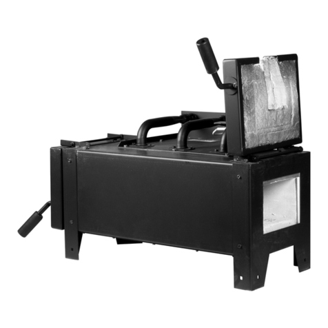
8PrimeFire 100, Oil, Operating Instructions, Edition 9.12
To set the initial oil tip position, set the oil tip flush with
the atomizing tip, then rotate the oil tube two full turns
back from flush. Two turns = 1.5 mm = 0.06 inch.
■Never operate this burner with the atomizing
oxygen orifice completely closed; this will cause it
to inject oil into the furnace without atomization,
which will cause a severe safety-related incident.
Notes on Burner Cooling
Use the following guidelines to make sure that the cooling
requirements for the burner are in place before installing
the burner.
■Combustion and atomizing oxygen cool the burner
and block, as well as supporting combustion. The
burner oxygen nozzles and fuel oil atomizing
assembly are made of a heat-resistant steel alloy,
but they can still be damaged if they are exposed
to furnace radiation without cooling oxygen flows
in the form of combustion and atomizing oxygen.
For oxy/oil firing, the fuel oil atomizing assembly is
extended well into the pre-combustor. It is roughly 63.5
mm (2.5 inches) back from the hot face of the pre-
combustor. At this location, the atomizing assembly must
have atomizing oxygen flow for cooling purposes at all
times. Otherwise, it could suffer extensive heat damage or
meltdown.
The flow should be 10—23 Nm3/h (320 to 800 SCFH).
The combustion oxygen flow of about 27 Nm3/h (1,000
SCFH) must also be maintained, to keep the pre-
combustor cool and free from furnace gases which could
deposit particulates/volatile matter on the precombustor
inner wall. In case of an emergency or power failure, pull
the entire burner body out to the pre-combustor opening
and plug the pre-combustor with a refractory plug or high-
temperature fiber wool blanket.
Before installing the burner, have the combustion oxygen,
atomizing oxygen, and the fuel oil supply lines ready and
pressurized, so that within a few minutes of the burner
being placed in the block, a combustion oxygen flow of
about 27 Nm3/h (1000 SCFH) and atomizing oxygen of 10
Nm3/h (320 SCFH) can be started to provide cooling. The
only action required to start the oxygen flow at this point
should be to open the ball shutoff valve closest to the
burner.
Installing the Burner
After the mounting hardware is installed and cooling
requirements are in place, use this procedure to install the
burner.
NOTE: Before installing the burner, make sure that all
steps to achieve minimum oxygen flow through the burner
can be completed within less than five minutes after
burner installation.
■If the burner is not level, premature failure of the
precombustor is possible
1. Clamp the burner to the mounting section using the
clamping mechanism on the burner. Do not over-
tighten the clamps. Use only enough pressure to
ensure a firm seal of the burner to the pre-
precombustor. Insert the safety pins through the
clamping mechanism to lock it in place.
2. Connect the combustion oxygen, atomizing oxygen,
and the fuel oil hoses to the burner.
3. If the oil purge system is supplied, set the purge/oil
switch to Purge.
4. Open the combustion oxygen shutoff valve closest to
the burner to begin flowing oxygen at a rate of about
27 Nm3/Hr (1000 SCFH) through the burner to
provide cooling.
5. Open the atomizing oxygen shutoff valve closest to
the burner to begin flowing oxygen at a rate of about
10 Nm3/Hr (320 SCFH) through the burner to provide
cooling.
■Make sure the furnace is at a minimal temperature
for auto-ignition, 800°C (1472°F).
Firing the Burner with Oil
After installing the burner, use this procedure to fire the
burner using fuel oil.
NOTE: When firing oil, the oil tube tip must be retracted
into the atomizing nozzle 0.03" at a minimum. Issues may
occur if the oil tube is mounted in the incorrect position.
NOTE: If heavy (#6) oil is used, the oil temperature should
be adjusted to maintain an oil viscosity of about 20
centistokes (between 90—110 SSU) at the burner. Higher
oil viscosities are desirable, short of the oil flashing or the
small amount of water found in heavy oil turning to steam.
WARNING
WARNING
WARNING
WARNING


