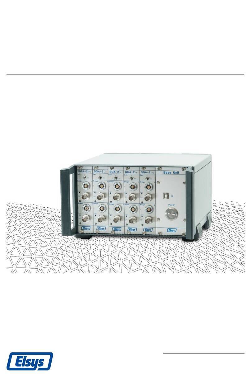
Elsys SGA-2 User manual

Strain Gauge Amplifier
User Manual
Elsys AG
Mellingerstrasse 12 +41 56 496 01 55
CH-5443 Niederrohrdorf www.elsys-instruments.com


Strain Gauge Amplifier User Manual V2.0
© Elsys AG 1/18
Table of contents
1Overview.......................................................................................................................2
1.1 Key Capabilities ......................................................................................................2
1.2 Versions..................................................................................................................2
1.2.1 Boxed Version .................................................................................................2
1.2.2 Rack Version....................................................................................................2
2Cable Pin Assignment ...................................................................................................3
3Operating Modes, Block Diagrams ...............................................................................4
3.1 Full Bridge ..............................................................................................................4
3.2 Half Bridge..............................................................................................................5
3.3 Quarter Bridge .......................................................................................................5
4Configuration and Settings ...........................................................................................6
4.1 Hardware Settings..................................................................................................6
4.2 Front LEDs ..............................................................................................................6
4.3 Software Settings ...................................................................................................7
4.3.1 AppConfig.xml .................................................................................................7
5Connectors and Configuration......................................................................................8
5.1 Front View..............................................................................................................8
5.2 Rear View ...............................................................................................................8
5.3 Calculations............................................................................................................9
5.3.1 Quarter Bridge.................................................................................................9
5.3.2 Half Bridge.......................................................................................................9
5.3.3 TranAX Formula for Load calculation..............................................................9
6Open SGA Box Enclosure ............................................................................................10
7SGA2 MK2 Module......................................................................................................11
7.1 Configuration .......................................................................................................11
7.2 Internal Quarter Bridge Resistor R4.....................................................................12
8Safety Information (Base Unit EL-SGBU only) ............................................................13
9Base Unit EL-SGBU Specifications...............................................................................14
10 Specifications of the SGA2-Box MK2.......................................................................14
11 Amplifier Specifications...........................................................................................15
12 Notes .......................................................................................................................16

Strain Gauge Amplifier User Manual V2.0
© Elsys AG 2/18
1Overview
The Strain Gauge Amplifier SGA-2 MK2 is designed as a differential front-end amplifier to
connect full, half or ¼ bridge strain gauges with internal bridge completion.
Applications:
•Deformation testing for material characterization
•High speed dynamic material deformation
•Load Cell measurements
1.1 Key Capabilities
•Internal ½- and ¼ bridge completion
•Two independent channels per module
•Gain x1, x10, x100
•4-wire and 6-wire technique
•1.5 MHz bandwidth at gain x1, x10
•Low offset voltage drift
•Low output noise
•Auto-Offset compensation
•USB or RS485 interface for configuring all settings and read back of the actual out-
put signal.
1.2 Versions
There are two versions available:
1.2.1 Boxed Version
•2-Channel modules SGA-Box/6, SGA-Box/7 or SGA-Box/16
•USB interface (emulated COM port)
•External power supply
1.2.2 Rack Version
•2-Channel Rack-Modules SGA-Box/6, SGA-P/7 or SGA-P/16
•Amp-BU-10 (for up to 5 modules / 10 channels)
•Amp-BU-24 (for up to 12 modules / 24 channels)
•USB interface (emulated COM port) for accessing all installed amplifier (Internally
over RS485)

Strain Gauge Amplifier User Manual V2.0
© Elsys AG 3/18
2Cable Pin Assignment
Elsys Instruments SGA cable assembly with LEMO circular push pull connectors, straight
plug male with cable collet. CLAD72 defines the maximum outer cable diameter, e.g.
7.2mm.
Connector type
Lemo part number
16 pin
Lemo FGG.2B.316.CLAD72
7 pin
Lemo FGG.1B.307.CLAD72
6 pin
Lemo FGG.1B.306.CLAD72
Recommended cable for 7 pin connectors:
Data cable, shielded 4x2x0.25 mm², bare copper, stranded wire
E.g.: VOLLTRON-TWIST-CY 4X2X0,25mm², VOLLAND
6-pin
7-pin
16-pin
Color1)
Signal
3
6
1
6
1
4
White
Brown
+Vexc
-Vexc
twisted
2
5
2
5
3
2
Green
Yellow
+Sense
-Sense
twisted
4
1
3
4
5
6
Grey
Pink
Vin+
Vin-
twisted
-
7
9
Blue
¼ Bridge
-
1) Applies to cables manufactured by Elsys Instruments
Figure 1: Solder cup view of male connector

Strain Gauge Amplifier User Manual V2.0
© Elsys AG 4/18
3Operating Modes, Block Diagrams
Full Bridge and Half Bridge can be used as a 4-wire or 6-wire configuration. 6-wire is rec-
ommended for long sensor cables for brownout compensation. In all cases, there has to
be a Full Bridge at the end, either externally in the sensor, the Load Cell, or in combination
with the internal Half- and Quarter Bridge.
Sensor
Int. Half Bridge
Int. Quarter Bridge R4
Full Bridge
Disabled
Not assembled
Half Bridge
Enabled
Not assembled
Quarter Bridge
Enabled
assembled
3.1 Full Bridge

Strain Gauge Amplifier User Manual V2.0
© Elsys AG 5/18
3.2 Half Bridge
3.3 Quarter Bridge

Strain Gauge Amplifier User Manual V2.0
© Elsys AG 6/18
4Configuration and Settings
Each SGA module can be configured by its on-board dip-switches or with the free availa-
ble SGA 2.0 configuration software. Please contact your distributor or Elsys Instruments
directly to get a copy of this application: info@elsys-instruments.com
4.1 Hardware Settings
Hardware configuration is straight forward and (except for gain) individually configurable
for both channels.
•Half Bridge internal or external
•Wiring with 4 or 6 wires
•Excitation voltage 10V or 5V
•Gain toggle switch front 1/10/100 both channels together.
For independent gain selection, software settings are required.
The “Board Address”(rotary switch) has to be selected ones for a board. In the boxed
version, this address is per default set to 0. In a rack version with multiple boards, each
device needs a unique address.
Figure 2: Configuration settings
Dip-Switches position down to the board means ON.
4.2 Front LEDs
There is a two-colour LED (red and green) for each channel.
Colour LED
Description
Off
Output signal outside ± 100mV
Green
Output signal within ± 100mV
Red
Error during Zero compensation
Orange
(Green and Red)
Error during Zero compensation, currently gain settings within
± 100mV

Strain Gauge Amplifier User Manual V2.0
© Elsys AG 7/18
4.3 Software Settings
With the free available software configuration tool SGA 2.0, all settings can be done. Set-
tings will be saved for each channel. Reset can be done per software command, or by
pressing the front Zero buttons for more than 3 seconds. Afterwards, he Hardware set-
tings of each channel are active.
All serial ports (COM-Ports) will be scanned for an
available SGA mk2 device. With the two buttons
Connect and Disconnect, the device can be
opened and released again.
All Settings of the Dip-Switches can be done in in
the configuration field for each cannel. Also Gain
can be set individually for each channel.
The Check box "Enable live value" returns the
measured voltage of the selected channel accord-
ing to its configuration. Factory settings are set to
voltages.
Please note that the live value or GETADC return value has a precision of approx.
2% and is meant to see a trend or position of a sensor or measurement. For high
speed and high resolution, an Elsys DAQ system is required.
4.3.1 AppConfig.xml
Additional Settings can be done in the AppConfig.xml file. Please note that any changes
have an impact to the communication with the SGA mk2 devices. In case of troubles, de-
lete this file, restart the SGA 2.0 application and it will be created again with functional
default values.
To use just one fixed Comport, edit this file and replace the line <Comport /> with the
following entry:
<ComPort>COM9</ComPort>
Please check the device manager for the serial port you are using.

Strain Gauge Amplifier User Manual V2.0
© Elsys AG 8/18
5Connectors and Configuration
5.1 Front View
On the front is one common toggle switch for both cannels to set Gain to 1, 10 or 100.
Each channel has a LEMO input, a BNC output, a push button for Zero compensation and
a status LED.
Green means the output voltage is between ± 100mV. Outside of this range the LED will
switch off. During Zero compensation procedure, the LED turns red and flashes green
three times. In case of an error, it will stay red. Orange means there was an error during
Zero compensation in at least one range, the actual select range is within ± 100mV, there-
fore green.
To reset the software settings back to hardware settings of the internal DIP switch, the
Zero compensation button has to be pressed for more than 3 seconds. The red LED will
flash 4 times.
Figure 3: Front view SGA2-Box
5.2 Rear View
The SGA-2 MK2 will be powered with an external 12V power supply. There is a 4mm con-
nector for earthing, a USB type B socket for PC connection and a phoenix connector as an
external calibration input. This can be used in combination with a PLC or any other con-
troller device. The input Ext. Zero is used to trigger a Zero Offset compensation for both
channels with an external 5-24VDC pulse.
Figure 4: Rear view SGA2-Box

Strain Gauge Amplifier User Manual V2.0
© Elsys AG 9/18
5.3 Calculations
Strain Gauge sensors are very sensible on temperature changes. For compensating the
change in resistance due the temperature change, a second strain gauge sensor can be
used as completion resistor R4. This “dummy” sensor must be mounted as close as pos-
sible to the active sensor Rg but must not follow the deformation of the device under test.
Even if two sensors are used, it is still a quarter bridge as only one sensor is active.
5.3.1 Quarter Bridge
5.3.2 Half Bridge
5.3.3 TranAX Formula for Load calculation
G =1;Amplifier Gain
S[mV/V]=10 ; Sensitivity
LR[Kg]=1; Rated Load
L[Kg]=0.5 ; Applied Load
Vex[V]=10 ; Excitation Voltage
Vout[mV]=G *Vex *S *L/LR
; Calculate the applied load from the output voltage
Load =Vout *LR /(G *Vex *S)

Strain Gauge Amplifier User Manual V2.0
© Elsys AG 10/18
6Open SGA Box Enclosure
In case of changing the Dip-Switch settings, the SGA boxed version has to be opened.
Please note that all settings can be done with the Elsys SGA 2.0 Tool.
Necessary tools:
T8 Torx or star screwdriver
Remove the connector for external calibration on the
rear side.
Loose and remove the two Torx screws using a T8 Torx
or star screwdriver.
Pull gently on the BNC connectors to get the Board out
of its housing.
Be careful; don't pull off the earthing cable connected
to the rear side.
Figure 5: Multiple pictures how to open the SGA2 MK2 box

Strain Gauge Amplifier User Manual V2.0
© Elsys AG 11/18
7SGA2 MK2 Module
Each channel of the Strain Gauge Amplifier can be configured induvial. Either by DIP
switch settings on the board or with the free available SGA 2.0 configuration tool.
The red marked toggle switch will be used for both channel, set the gain to 1, 10 or 100.
Individual configuration has to be done per software.
Figure 6: Top view of the SGA2 MK2 board
7.1 Configuration
For each channel two potentiometers are available. These will be used for Excitation volt-
age adjustment for 10V and 5V. Generally, there is no need to do any changes on these
potentiometers.
For each channel, there are four DIP switches available. According to the position of these
switches, the excitation voltage will be set to 10V or 5V, 6-wire or 4-wire, enable internal
or external Half Bridge. The fourth DIP switch is not used at the moment.
The rotary switch defines the board address. This will be set to "0" for boxed devices. For
rack version, the board address will be defined according its position in the rack.
Figure 7: Configuration settings

Strain Gauge Amplifier User Manual V2.0
© Elsys AG 12/18
7.2 Internal Quarter Bridge Resistor R4
There are two screw terminals, one for each channel, for assembling the internal Quarter
Bridge R4 Resistor. This will be necessary in case of using a Quarter Bridge sensor. The
resistance of R4 has to match the one of the used sensors.
Figure 8: 1/4 Bridge Resistor R4

Strain Gauge Amplifier User Manual V2.0
© Elsys AG 13/18
8Safety Information (Base Unit EL-SGBU only)
•This instrument is intended for indoor use and should be operated
in a clean, dry environment.
•It must not be operated in explosive, dusty, or wet/damp
atmosphere.
•Make sure this product's operating environment is kept within
the following parameters prior to use:
oTemperature: 0 to 45 °C, note: Direct sunlight, radiators and other heat
sources should be taken in account when assessing the ambient tempera-
ture.
oHumidity: Maximum relative humidity 80% for temperatures up to 31 °C
decreasing linearly to 50% relative humidity at 45 °C
oAltitude: Up to 2'000m
•The design of the instrument has been verified to conform to the
EN 61010-1 safety standard per the following limits:
- Installation (Overvoltage)
Category II (Main Supply Connector) and
Category I (Measuring Terminals)
- Pollution Degree 2
- Protection Class I
Warning
Lethal voltages exist inside the instrument. Only qualified technicians of supplier
staff are authorised to open the case of the Base Unit. Otherwise warranty will be
lost!
Always ensure that power cord is removed before
opening the case.

Strain Gauge Amplifier User Manual V2.0
© Elsys AG 14/18
9Base Unit EL-SGBU Specifications
Case
Amp-BU-24 19“-Rack Case approx. 480x290x140 mm
Amp-BU-10 Desktop Case approx. 250x290x140 mm
Number of Channels per Plug-In-Module
2
Plug-In Capacity
Amp-BU-24 up to 24 channels, 12 modules
Amp-BU-10 up to 10 channels, 5 modules
Main Power Voltage
100 to 250 VAC, 50/60 Hz
Power consumption
max. 75 W
Inlet Protection Fuse
Type 5x20 mm, only T2AL fuses must be used.
There are two fuses installed.
Weight
max. 7.5 kg incl. 12 Plug-In-Modules
0.25 kg Plug-In-Module
10Specifications of the SGA2-Box MK2
Case
Aluminium case
approx. 110x45x185 mm (WxHxD)
Number of channels per box
2
Power Supply
12 VDC, max. 700mA
By a Mains Adapter
100 to 240 VAC, 50/60Hz
Weight
0.65 kg (incl. Mains Adapter)

Strain Gauge Amplifier User Manual V2.0
© Elsys AG 15/18
11Amplifier Specifications
Configurable Modes
6-wire, 4-wire, Full Bridge,
½ Bridge, ¼ Bridge
Gain
x1, x10, x100
Indication of adjusted Bridge
Front-LED
Input stage
Differential Amplifier
Bandwidth
1.5 MHz (G=1, 10)
600 kHz (G=100)
Input Impedance
2 x 1 MΩ II approx. 25 pF to GND
Input Bias Current
< ±60 nA
Offset Voltage (Referred to Output)
< ±2.5mV, Note *1)
Offset Voltage Drift (Referred to Output)
< ± (30 + 1 * Gain) µV/°C, Note *1)
Gain Error
< ±0.1 % (G= 1, 10), < ±0.5 % (G=100)
Slew Rate (10 - 90 %)
< 300ns (Gain=1, 10)
< 700ns (Gain=100)
Output Noise
Int. ½ Bridge Off
Int. ½ Bridge On
Bandwidth
Bandwidth
Gain
100 kHz
Full
100 kHz
Full
x 1
0.03 mVrms
0.3 mVpp
0.3 mVrms
1.5 mVpp
0.05 mVrms
0.8 mVpp
0.4 mVrms
6 mVpp
x 10
0.08 mVrms
0.6 mVpp
0.5 mVrms
5 mVpp
0.3 mVrms
2.5 mVpp
2.5 mVrms
40 mVpp
x 100
0.6 mVrms
4 mVpp
1.5 mVrms
15 mVpp
3 mVrms
20 mVpp
20 mVrms
150 mVpp
Note: *1) after 1h Warm-Up Time at Tamb = 25°C and autozero
Output Impedance
50 Ω +/-1%
Output Voltage Swing
max. ±5 V (no Load)
max. ±2 V (Load = 50 Ω)
Input Voltage (Protected Input Range)
max. ±42 V (Signal Inputs)
max. ±5 V (Excitation Voltage Pins)
Excitation Voltage
10 V (±5V) or 5 V (±2.5V), ±0.1%
Excitation Voltage Load
max. 90 mA
Internal ½ Bridge Asymmetry
max. ±0.1% (= 10 mV @ 10V)
Power Supply
12 Vdc ±10%, max. 5 W per 2 Ch
Operating Temperature
0 to 45 °C
Storage Temperature
-20 to 60 °C
Relative Humidity
< 80 % (up to 31 °C)
decreasing to < 50% at 31 to 45°C
Operating Elevation
max. 2’000 m
Connector Type Output
BNC
Connector Type Input
Lemo 16pol. Model FGG.2B.316.xx
Lemo 7pol. Model FGG.1B.307.xx
Lemo 6pol. Model FGG.1B.307.xx

Strain Gauge Amplifier User Manual V2.0
© Elsys AG 16/18
12Notes

Strain Gauge Amplifier User Manual V2.0
© Elsys AG 17/18

Strain Gauge Amplifier User Manual V2.0
© Elsys AG 18/18
Document information
Filename: SGA2 MK2 Manual EN.docx
Status: Released
Last modification
Date: 19.02.2020
Author: Andreas Boillat / Thomas Berger
Other manuals for SGA-2
1
Table of contents
Other Elsys Amplifier manuals
