ELT Sensor CD-300 User manual

ELT Sensor Corp. Ver. 2.1 (Jan. 2014)
General
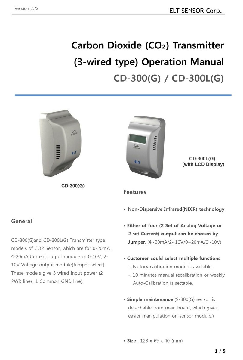
CD-300 and CD-300NL are Transmitter type
models of CO2 Sensor, which are for 0-20mA ,
4-20mA Current output module or 0-10V, 2-
10V Voltage output module(Jumper select)
These models give 3 wired input power (2
PWR lines, 1 Common GND line).
Features
• Non-Dispersive Infrared(NDIR) technology
is used to measure CO₂ levels.
• CO2 concentration can be measure as
Analog Voltage /Current value
(4~20mA / 2~10V or 0~20mA / 0~10V)
• Input power 24VAC or 24VDC
•.CD-300NL (without Display) is available.
• Customer could select multiple functions
-. Either of Factory calibration mode or
automatic recalibration mode with 1 month
period after 3 days.
-. 10 minutes manual recalibration function
is available as needed.
-. CO2 measuring range change between
0~10,000ppm is available.
• Simple maintenance (S-200 sensor module
are separately connected to main board so
that easily managed)
• Size : 123 x 69 x 40 (mm)
ELT Sensor
Carbon Dioxide (CO₂) Transmitter
(3-wired type) Operation Manual
CD-300 / CD-300NL
CD-300NL (without
LCD Display)
CD-300
(with LCD Display)

ELT Sensor Corp. Ver. 2.1 (Jan. 2014)
CD-300 Transmitter
Specifications
General Performance
Operating Temperature range
0 ~ 50℃
Operating Humidity range
0 ~ 95% RH (Non-condensing)
Storage Temperature
-20℃ ~60℃
CO₂ Measurement
Sensing Method
NDIR (Non-dispersive Infrared)
Measurement Range
0 to 2,000 / 3,000 / 5,000 / 10,000ppm
( with jumper position change)
Accuracy
±30ppm ±5%
Response Time(90%)
150 seconds
Sampling Interval
4 sec.
Operation mode selection
Two operation mode are available
Factory calibration mode and
Automatic calibration mode
Two manual recalibration methods are
available with manual recalibration by change
of J2 & J4 or by using TRB-100 Jig (TRB-100
Jig : additionally purchasable)
Electrical Data
Input Power
24VAC, 24VDC ± 20%, 50/60Hz
(3-Wired)
Output Signals
4 ~ 20mA or 2 ~ 10VDC
0 ~ 20mA or 0 ~ 10VDC
, (Jumper selectable
-voltage output or current output)
Dimensions (unit : mm)

ELT Sensor Corp.
Front Inside View
Rear View
Jumper : A
Jumper : B
Jumper : C
Ver.
Jumper Function Descriptions
■ Jumper A (J7, J3) group :
Current output and range selection.
V : Voltage output
I : Current output
0~20mA : 0~20mA output
0~10V output @
4~20mA : 4~20mA output
2~10V output @
Example setting :
ð Current output and 0
■ Jumper B(J11) group :
range selection.
10K ppm : 0 ~ 10,000ppm CO2
5K ppm : 0 ~ 5,000ppm CO2
3K ppm : 0 ~ 3,000ppm CO2
2K ppm : 0 ~ 2,000ppm CO2
Jumper : C
Ver. 2.1 (Jan. 2014)
Jumper Function Descriptions
group : Voltage,
Current output and range selection.
0~20mA : 0~20mA output @ Current.
@ Voltage
4~20mA : 4~20mA output @ Current.
@ Voltage.
output and 0~ 20mA output
group : CO2 Measurement
10K ppm : 0 ~ 10,000ppm CO2
5K ppm : 0 ~ 5,000ppm CO2
3K ppm : 0 ~ 3,000ppm CO2
2K ppm : 0 ~ 2,000ppm CO2

ELT Sensor Corp.
Example setting :
1) 0~2,000ppm setting and LCD
Real number : 862ppm
(Notice : when jumper set on
2000ppm ~ 10,000ppm position, the
LCD number is the real ppm)
Ver.
and LCD
number : 862ppm
(Notice : when jumper set on from
2000ppm ~ 10,000ppm position, the
LCD number is the real ppm)
2) 30,000ppm setting
(right end postion+3
Real number : 8,710ppm,
(Important notice : when jumper set
range (20,000~100,000ppm position
real ppm from LCD
calculated by LCD display number x 10
■ Jumper C (J2, J4) group :
mode selection and 10 minute
function
Factory calibration mode:
Both jumpers set to ‘OFF’,
Automatic Recalibration mode :
If users want to operate this CD
monthly automatic recalibration mode, please
set to ‘ON’ position (ACDL mode) (Auto
calibration acts first 3day, and every 30days
after power on)
10’ RECAL : Users can do
recalibration (correction)
when sensor showed much fault ppm.
(Pose Jumper-cap to ‘ON
Ver. 2.1 (Jan. 2014)
ppm setting and LCD
(right end postion+3rd position)
Real number : 8,710ppm, 11,250ppm
when jumper set on high
ppm position), the
reading must be
calculated by LCD display number x 10 )
group : Operation
minute Recalibration
, ’OFF’ position
calibration mode :
If users want to operate this CD-300 as
automatic recalibration mode, please
position (ACDL mode) (Auto
calibration acts first 3day, and every 30days
Users can do 10 minutes
(correction) manual function
much fault ppm.
ON’ position and wait

ELT Sensor Corp.
over 11 minutes. After the setting of
air-flowing status to be 400ppm finished
move back the Jumper-cap to
again.)
(For more information, please refer to detailed
recalibration manual)
Example setting :
ð Monthly Automatic
operation mode
Wiring Method
VIN+: 24VAC P or 24VDC+,
VIN-: 24VAC N or 24VDC-(GND),
A-OUT: Output signal (Voltage or Curr
Ver.
setting of ambient
flowing status to be 400ppm finished,
cap to ‘OFF’ position
please refer to detailed
Monthly Automatic recalibrating
operation mode
(GND),
(Voltage or Current).
Wire connector.
Output signal calculation
Ex) 3,000ppm range 0~10V mode.
Read voltage 3.234V
3,000ppm / 10V * 3.234 = 970 ppm.
Ex) 3,000ppm range 2~10V mode.
Read voltage 3.234V
(3.234V - 2V) * (3000ppm / 8)= 462 ppm.
--------------------------------------------------
ELT Sensor Corp.
(Chunui Technopark 101-909) 36, Bucheon
Wonmi-gu, Bucheon-si, Gyeonggi-do, 420
Phone : .82-32-719-8055
Fax : 82-70-8677-8055
http://www.eltsensor.co.kr
ELT Sensor All right reserved
Subject to change without notice. Printed in KOREA
Ver. 2.1 (Jan. 2014)
ire connector.
examples
Ex) 3,000ppm range 0~10V mode.
3,000ppm / 10V * 3.234 = 970 ppm.
Ex) 3,000ppm range 2~10V mode.
2V) * (3000ppm / 8)= 462 ppm.
--------------------------------------------------
909) 36, Bucheon-ro 198beon-gil,
do, 420-857, Korea
Subject to change without notice. Printed in KOREA
This manual suits for next models
1
Table of contents
Other ELT Sensor Transmitter manuals
Popular Transmitter manuals by other brands
Linear
Linear MULTI-CODE 3083 installation instructions
OTS
OTS ET4100CPp-TS manual
Dwyer Instruments
Dwyer Instruments 616W Series Installation and operating instructions
Labom
Labom PASCAL CV4 Operating instruction
Comcast
Comcast 1310nm TX manual
Panduit
Panduit Altona Omega AT-OME-SW21-TX-WPC installation guide
M-system
M-system M2LPM instruction manual
F-S Electronics
F-S Electronics Rangemaster X-Treme Series instructions

M-system
M-system M6SXU instruction manual
SAGEMCOM
SAGEMCOM Dr. Neuhaus ZDUE-GPRS-PLUS-VI user manual

Panasonic
Panasonic LightPix AE20 user manual
Transmitter Solutions
Transmitter Solutions Firefly 3 manual
