manuals.online logo
Brands
  1. Home
  2. •
  3. Brands
  4. •
  5. Linear
  6. •
  7. Transmitter
  8. •
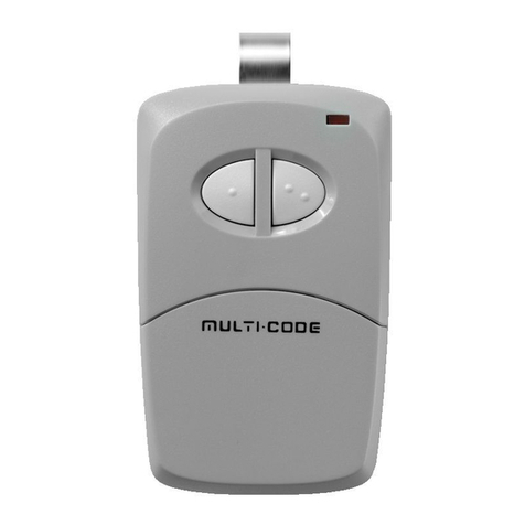
  9. Linear MULTI-CODE 3083 User manual

Linear MULTI-CODE 3083 User manual

®
INSTALLATION INSTRUCTIONS
MODEL 3083
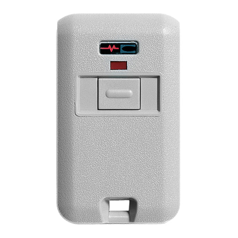
TWO CHANNEL MINI-TRANSMITTER
Congratulations! You have just purchased a Multi-Code
Digital Transmitter, which we believe to be the nest product
of its kind on the market. With a little care this transmitter
should provide you with many years of excellent service.
Please take a moment to read the following instructions
and you will nd that setting your new transmitter will be
quite an easy matter.
ACCESSING THE CODE SWITCH AND BATTERY
COMPARTMENT
The model 3083 two channel Mini-transmitter case is
composed of 2 halves which are held together by a small
phillips head screw. Removing this screw will allow access
to the code switches and the battery compartment (see
Diagram #1, below).
BATTERY
LED
CODE SWITCH #1
CODE SWITCH #2
DIAGRAM #1
TRANSMITTER WITH TOP
HALF OF CASE REMOVED
TRANSMITTER TOP COVER
165
PLEASE NOTE
Nortek Security & Control has devoted a great deal of time and research in
order to provide the most reliable equipment possible. Certain limitations
must be observed.
1) MULTI-CODE radio components must conform with FCC Part
15 requirements. For this reason, the range and power of our
radios is within specied limits.
2) As with all manufacturers, Nortek Security & Control’s radios
must accept all signals that they receive. This may, in rare
instances, create difculty.
3) You should test your entire system occasionally in order to be
sure that all components are working in good order.
4) Nortek Security & Control’s dealers can provide you with
information regarding the use of our radio controls, and can
provide valuable installation and operation information, when
requested.
WARNING: Changes or modications not expressly approved by the
manufacturer could void the user’s authority to operate the equipment.
Note: This equipment has been tested and found to comply with the
limits for a Class B digital device, pursuant to Part 15 of the Federal
Communications Commission (FCC) rules. These limits are designed to
provide reasonable protection against harmful interference in a residential
installation. This equipment generates, uses and can radiate radio
frequency energy and, if not installed and used in accordance with the
instructions, may cause harmful interference to radio communications.
However, there is no guarantee that interference will not occur in a
particular installation. If this equipment does cause harmful interference
to radio or television reception, which can be determined by turning
the equipment off and on, the user is encouraged to try to correct the
USA & Canada Toll Free (800) 421-1587
or dial (760) 438-7000
www.nortekcontrol.com
interference by one or more of the following measures:
• Reorient or relocate the receiving antenna.
• Increase the separation between the equipment and receiver.
• Connect the equipment into an outlet on a circuit different from
that to which the receiver is connected.
• Consult the dealer or an experienced radio/TV technician for help.
PRINT INSTRUCTIONS:
INSTR,INSTL,MC3083,2 BTN MINI-TX PN: 214944 Rev-C, INK: Black, MATERIAL: 20 LB, MEAD BOND, SIZE: 9.500” X 4.600”, SCALE: 1-1
FCC& IC Notice
This device contains licence-exempt transmitter(s) / receiver(s) that
comply with Innovation, Science and Economic Development
Canada’s licence-exempt RSS(s). Operation is subject to the
following two conditions:
1. This device may not cause interference.
2. This device must accept any interference, including interference
that may cause undesired operation of the device.
L’émetteur/récepteur exempt de licence contenu dans le présent
appareil est conforme aux CNR d’Innovation, Sciences et
Développement économique Canada applicables aux appareils radio
exempts de licence. L’exploitation est autorisée aux deux conditions
suivantes:
1. L’appareil ne doit pas produire de brouillage;
2. L’appareil doit accepter tout brouillage radioélectrique subi,
même si le brouillage est susceptible d’en compromettre le
fonctionnement.
SELECTING A CODE
Before placing your transmitter into service, we urge you
to set your code in order not to interfere with neighboring
systems and to provide security for your own system. We
strongly urge that several coding schemes be avoided: ALL
ON; ALL OFF; 2, 4, 6, 8, 10 ON; 1, 3, 5, 7, 9 ON. These
positions are similar to our or other manufacturer’s test
positions, or are frequently used.
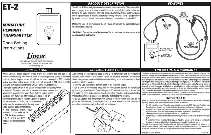
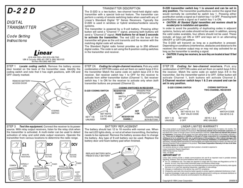
You will note that the model 3083 transmitter has two, ten
position code switches (Note: the switches are in the “on”
position when the switch is depressed toward the number,
see diagram #2). In order to simplify coding of your
transmitter as much as possible, observe the following:
123456789
1
0
ON
OFF
CODE SWITCH
SV
9A
DIAGRAM #2
If you have two single channel receivers: Set your
transmitter so that code switch #1 will match receiver #1.
Set code switch #2 on the transmitter to match receiver #2
(see Diagram #1).
If you have a MULTI-CODE 3021 or 3028 two channel
receiver: Set the receiver and both transmitter code
switch positions 1-9 to match. The tenth position on your
transmitter code switches are used for channel selection.
Channel 1 on the receiver is selected by moving the tenth
position of code switch #1 on the transmitter to the off
(open) position.
Channel 2 on the receiver is selected by moving the tenth
position of code switch #2 on the transmitter to the on
(closed) position. Once the codes have been set, check
the operation and reassemble the transmitter case.
MINI-TRANSMITTER INSTALLATION
This transmitter is completely self contained, including
battery and can be operated while held in hand or while
mounted in the car. It is supplied with “hook and loop”
fabric for easy mounting or it may be added to your
keychain using the slot provided.
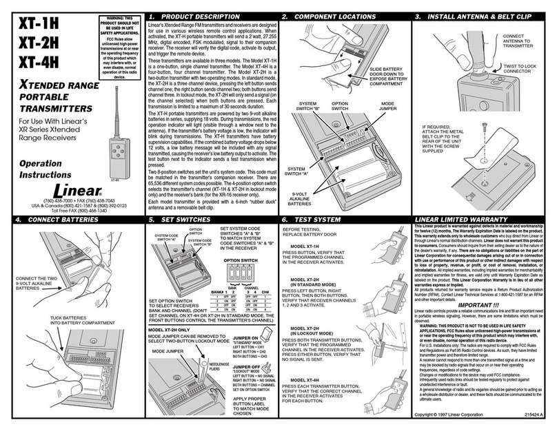
TRANSMITTER BATTERY REPLACEMENT
Replacement battery - 12 volt alkaline lighter battery
(Eveready A23 or equivalent).
The transmitter battery can be checked or changed by
removing the phillips head screw located on the back
of the case and carefully separating the case halves to
expose the circuit board and battery. Simply slide out the
old battery and slide in the new, remembering to observe
the battery polarity molded on the case in the bottom of
the battery compartment. Note that if the red LED on your
transmitter fails to light you most likely have a weak or
dead battery and it should be replaced (see diagram #1).
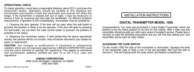
OPERATIONAL CHECK
To check operation, move back a reasonable distance
(about 50 ft.) and press the transmitter button. Operation
should be reliable at this distance but environment and
location of both the transmitter and receiver will affect the
range. If the transmitter is stowed well out of sight, it may
be necessary to remove it from its mounting and hold near
the windshield. Try different locations and positions.
If operation is still unsatisfactory, the problem may be
isolated by:
1. Checking the door operator. If the door will not open
when the wall button is pressed, the problem is likely
to be the operator. If the door will open by pressing
the wall button, but not when the radio control button
is pressed, the problem is probably in the radios.
2. Replacing the transmitter battery. If, after performing
the above operational checks, the controls still do not
function, they should be returned to your dealer for
repair or replacement.
WARRANTY
All MULTI-CODE door related products carry an eighteen (18) month
warranty against defects in workmanship or material. This warranty
begins at the date of manufacture, for eighteen months. Nortek Security
& Control warrantees our product only to our authorized dealers and
distributors and not to the end customer. If you have any questions about
our warranty, please ask your dealer to determine the nature and scope
of his warranty. Nortek Security & Control does not assume, and is not
responsible for, any real or consequential damages from claims against
the performance of our product, nor is it liable for any costs related to
loss of life, property, or revenue. Further, Nortek Security & Control is in no
way responsible for installation of our product, and will assume no costs
related to reinstallation or removal. Nortek Security & Control’s Warranty
is in lieu of all other warrantees, expressed or implied.
432
214944 Rev-C
Copyright © 2020 Nortek Security & Control LLC
Other Linear Transmitter manuals

Linear Mini-Code 3060 User manual

Linear

Linear Mini-Code 3060 User manual

Linear MVP User manual

Linear

Linear MVP User manual

Linear LMT-1 User manual

Linear

Linear LMT-1 User manual

Linear DXT-21/EC User manual

Linear

Linear DXT-21/EC User manual

Linear Multi-code 4140 User manual

Linear

Linear Multi-code 4140 User manual

Linear ET-2 User instructions

Linear

Linear ET-2 User instructions

Linear 1094 User manual

Linear

Linear 1094 User manual

Linear MULTI-CODE 4120 User manual

Linear

Linear MULTI-CODE 4120 User manual

Linear GT-31 User manual

Linear

Linear GT-31 User manual

Linear Multi-Code 3089 User manual

Linear

Linear Multi-Code 3089 User manual

Linear DXS-32/EC User manual

Linear

Linear DXS-32/EC User manual

Linear MULTI-CODE 4140 User manual

Linear

Linear MULTI-CODE 4140 User manual

Linear DX DXS-65 User manual

Linear

Linear DX DXS-65 User manual

Linear Multi-Code 4120 User manual

Linear

Linear Multi-Code 4120 User manual

Linear 1050 User manual

Linear

Linear 1050 User manual

Linear LINEARCOM3000 User manual

Linear

Linear LINEARCOM3000 User manual

Linear DXS-64 User manual

Linear

Linear DXS-64 User manual

Linear MegaCode MCT-3 User manual

Linear

Linear MegaCode MCT-3 User manual

Linear DXS-32 User manual

Linear

Linear DXS-32 User manual

Linear XT-4 User manual

Linear

Linear XT-4 User manual

Linear WT00Z-1 User manual

Linear

Linear WT00Z-1 User manual

Linear Multi-Code MCS1082 User manual

Linear

Linear Multi-Code MCS1082 User manual

Linear DT-3 Plus 1 Administrator guide

Linear

Linear DT-3 Plus 1 Administrator guide

Linear Delta-3 DTG User manual

Linear

Linear Delta-3 DTG User manual

Popular Transmitter manuals by other brands

Status Instruments SEM1610 user guide

Status Instruments

Status Instruments SEM1610 user guide

SWIT CW-S300 user manual

SWIT

SWIT CW-S300 user manual

Secure Wireless EV-F319 user manual

Secure Wireless

Secure Wireless EV-F319 user manual

GE HygroTrace user guide

GE

GE HygroTrace user guide

IFM Electronic Elector 600 operating instructions

IFM Electronic

IFM Electronic Elector 600 operating instructions

Emerson Rosemount 3051 quick start guide

Emerson

Emerson Rosemount 3051 quick start guide

Labom CX6001 Series operating instructions

Labom

Labom CX6001 Series operating instructions

Dwyer Instruments ProxiMity UL Series Installation and operating instructions

Dwyer Instruments

Dwyer Instruments ProxiMity UL Series Installation and operating instructions

Autonics KT-502H Series quick start guide

Autonics

Autonics KT-502H Series quick start guide

APG PT-405 Series installation guide

APG

APG PT-405 Series installation guide

Stingray STINGRAY 318LIPW V Series quick start guide

Stingray

Stingray STINGRAY 318LIPW V Series quick start guide

REIGN TX-100 manual

REIGN

REIGN TX-100 manual

Gold Apollo TE-310 user manual

Gold Apollo

Gold Apollo TE-310 user manual

Comnet FVT1031 Installation and operation manual

Comnet

Comnet FVT1031 Installation and operation manual

Endress+Hauser Proline 500 Brief operating instructions

Endress+Hauser

Endress+Hauser Proline 500 Brief operating instructions

MicroNet Tacktick manual

MicroNet

MicroNet Tacktick manual

Newham London Roger Touchscreen Mic user guide and troubleshooter

Newham London

Newham London Roger Touchscreen Mic user guide and troubleshooter

Crestron IM-TCC Operations & installation guide

Crestron

Crestron IM-TCC Operations & installation guide

manuals.online logo
manuals.online logoBrands
  • About & Mission
  • Contact us
  • Privacy Policy
  • Terms and Conditions

Copyright 2025 Manuals.Online. All Rights Reserved.