manuals.online logo
Brands
  1. Home
  2. •
  3. Brands
  4. •
  5. HK Instruments
  6. •
  7. Transmitter
  8. •
  9. HK Instruments RHT-MOD Series User manual

HK Instruments RHT-MOD Series User manual

Copyright HK Instruments 2021 www.hkinstruments. Installaon version 7.0 2021
INSTALLATION
INSTRUCTIONS
HUMIDITY TRANSMITTERS
RHT-MOD Series
• READ THESE INSTRUCTIONS CAREFULLY BEFORE
ATTEMPTING TO INSTALL, OPERATE OR SERVICE THIS
DEVICE.
• Failuretoobservesafetyinformaonandcomplywith
instruconscanresultinPERSONALINJURY,DEATHAND/OR
PROPERTY DAMAGE.
• Toavoidelectricalshockordamagetoequipment,disconnect
powerbeforeinstallingorservicinganduseonlywiringwith
insulaonratedforfulldeviceoperangvoltage.
• Toavoidpotenalreand/orexplosiondonotuseinpotenally
ammableorexplosiveatmospheres.
• Retaintheseinstruconsforfuturereference.
• Thisproduct,wheninstalled,willbepartofanengineered
systemwhosespecicaonsandperformancecharacteriscs
arenotdesignedorcontrolledbyHKInstruments.Review
applicaonsandnaonalandlocalcodestoassurethatthe
installaonwillbefunconalandsafe.Useonlyexperiencedand
knowledgeabletechnicianstoinstallthisdevice.
SPECIFICATIONS
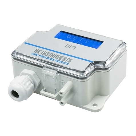
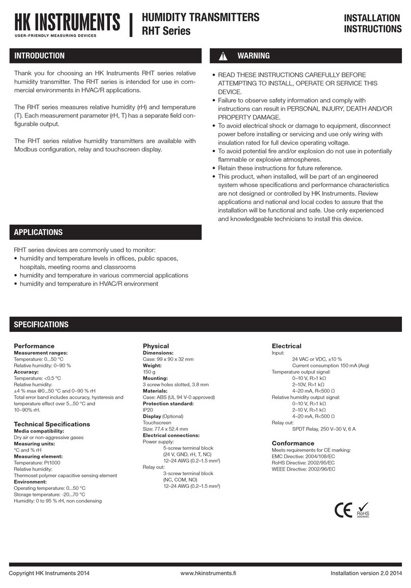
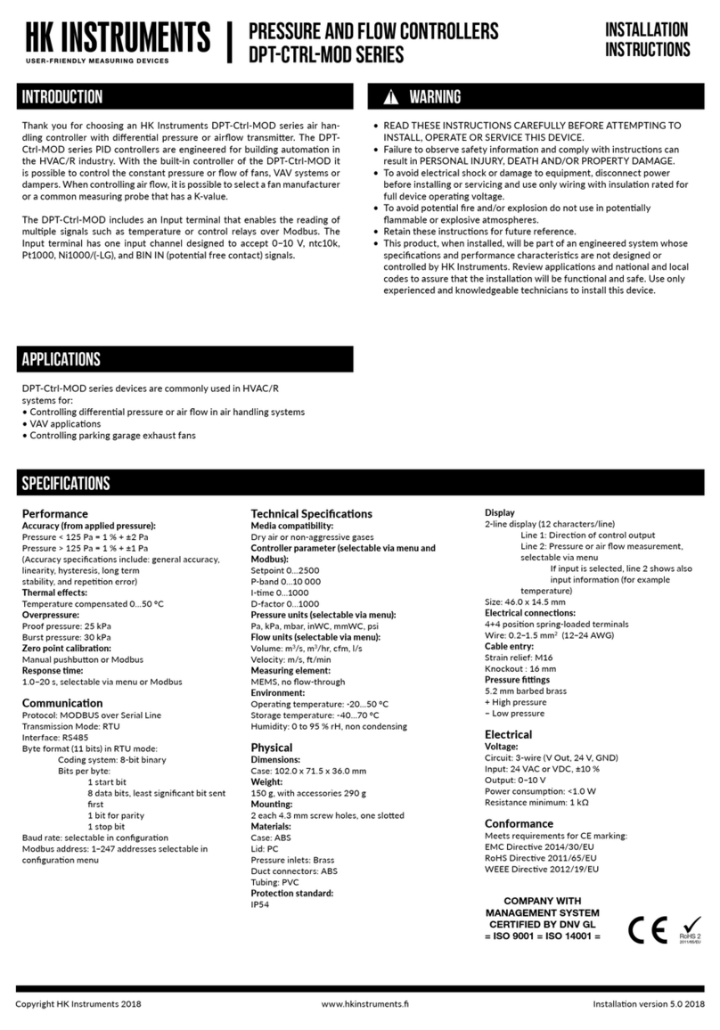
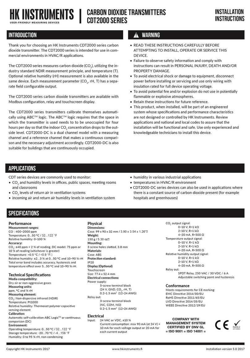
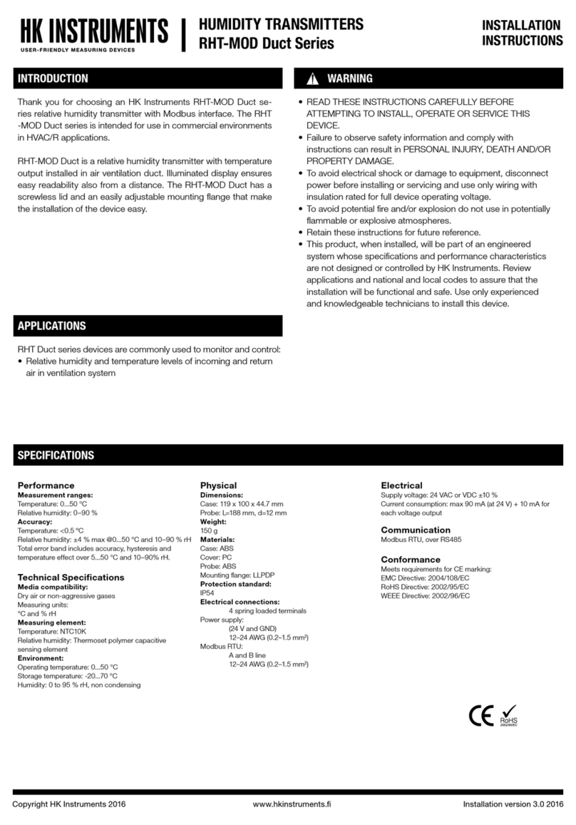
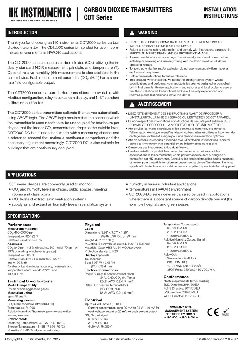
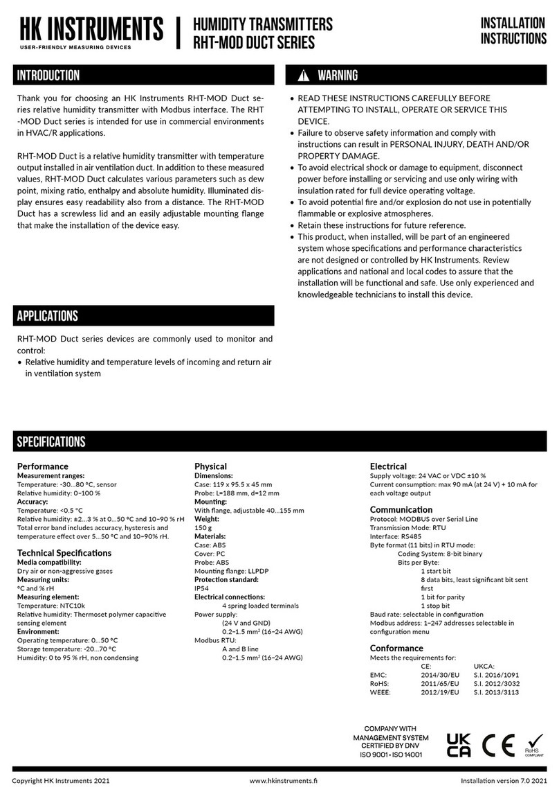
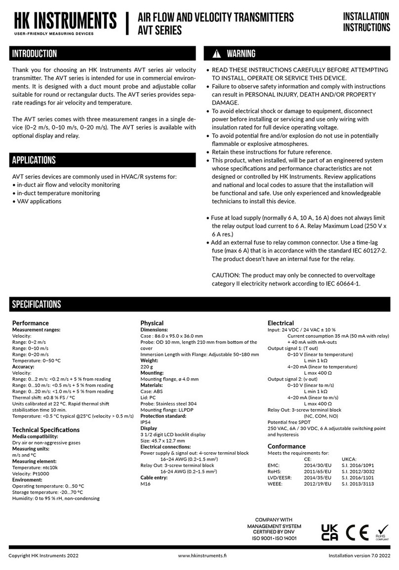
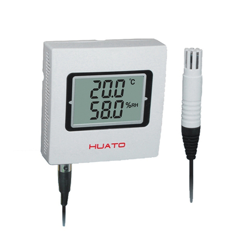
Thank you for choosing an HK Instruments RHT-MOD series rela-
vehumiditytransmier.TheRHT-MODseriesisintendedforusein
commercialenvironmentsinHVAC/Rapplicaons.
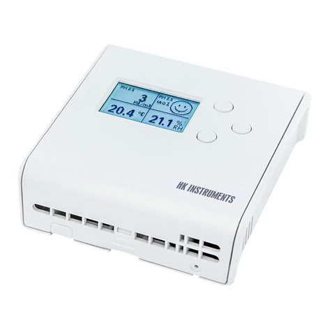
TheRHT-MODmeasuresrelavehumidity(rH),andtemperature(T).
RHT-MODdevicesareavailablewithlargetouchscreendisplaymak-
ingconguraonofthedevicequickandeasy.
RHT-MODseriesdevicesarecommonlyusedtomonitor:
•humidityandtemperaturelevelsinoces,publicspaces,hospitals,
meengroomsandclassrooms
•humidityandtemperatureinvariouscommercialapplicaons
•humidityandtemperatureinHVAC/Renvironment
SPECIFICATIONS
Performance
Measurement ranges:
Temperature:0...50°C
Relavehumidity:0–100%
Accuracy:
Temperature:<0.5ºC
Relavehumidity:±2...3%at0...50°Cand10–90%rH
Totalerrorbandincludesaccuracy,hysteresisand
temperatureeectover5...50°Cand10–90%rH.
Technical Specicaons
Media compability:
Dryairornon-aggressivegases
Measuring units:
°Cand%rH
Measuring element:
Temperature:Integrated
Relavehumidity:Thermosetpolymercapacive
sensingelement
Environment:
Operangtemperature:0...50°C
Storagetemperature:-20...70°C
Humidity:0to95%rH,noncondensing
Physical
Dimensions:
Case:99x90x32mm
Weight:
150g
Mounng:
3screwholessloed,3.8mm
Materials:
Case:ABS
Protecon standard:
IP20
Display
Touchscreen
Size:77.4x52.4mm
Electrical connecons:
Powersupply:
 5-screwterminalblock
 (24V,GND)
 0.2–1.5mm2(12–24AWG)
Relayout:
 3-screwterminalblock
 (NC,COM,NO)
 0.2–1.5mm2(12–24AWG)
Electrical
Input: 24VACorVDC,±10%
 Currentconsumpon:max90mA(at24V)+
 10mAforeachvoltageoutputor20mAfor
 eachcurrentoutput
Relayout:
 SPDTRelay,250VAC/30VDC/6A
 Adjustableswitchingpointandhysteresis
Oneanalogoutputforselectedmedia:
0/2*–10VDC,LoadRminimum1kΩ
*(2–10VDCdisplaymodelsonly)or
4–20mA,maximumload500Ω
Communicaon
Protocol:MODBUSoverSerialLine
TransmissionMode:RTU
Interface:RS485
Byteformat(11bits)inRTUmode:
 CodingSystem:8-bitbinary
 BitsperByte:
  1startbit
  8databits,leastsignicantbitsent
  rst
  1bitforparity
  1stopbit
Baudrate:selectableinconguraon
Modbusaddress:1−247addressesselectablein
conguraonmenu
Conformance
MeetsrequirementsforCEmarking:
EMCDirecve2014/30/EU
RoHSDirecve2002/95/EC
LVDDirecve2014/35/EU
WEEEDirecve2012/19/EU
INTRODUCTION WARNING
APPLICATIONS
COMPANY WITH
MANAGEMENT SYSTEM
CERTIFIED BY DNV GL
= ISO 9001 = ISO 14001 =
RoHS 2
2011/65/EU
Copyright HK Instruments 2021 www.hkinstruments. Installaon version 7.0 2021
SCHEMATICS
DIMENSIONAL DRAWINGS
INSTALLATION
STEP 1: MOUNTING THE DEVICE
1)Mountthedeviceinthedesiredlocaon(seestep1).
2)Routethecablesandconnectthewires(seestep2).
3)Thedeviceisnowreadyforconguraon.
WARNING!Applypoweronlyaerthedeviceisproperlywired.
Figure 1a - Surface mounng
1)Selectamounnglocaononthewallat1.2–1.8m(4–6)above
theoorandatleast50cm(20in)fromtheadjacentwall.Do
notblockdeviceairventsfromanydireconandleaveatleast
20cm(8in)gaptootherdevices.Locatetheunitinanareawith
goodvenlaonandanaveragetemperature,whereitwillbe
responsivetochangestotheroomcondions.TheRHT-MOD
shouldbemountedonaatsurface.
DonotlocatetheRHT-MODwhereitcanbeaectedby:
•Directsunlight
•Drasordeadareasbehinddoors
•Radiantheatfromappliances
•Concealedpipesorchimneys
•Outsidewallsorunheated/uncooledareas
2)Usethedeviceasatemplateandmarkthescrewholes.
3)Mountthewallplatewithscrews.
•Incorrectinstallaonmaycauseashiintemperatureoutput
•Securethelidwithalockingscrew,iftherelayisconnectedtothe
mainspower
Display locking
jumper
Jumpers
Contact pins for
relay terminal
Contact pins for
terminal block
Terminal block
Terminal block for relay
99.0
90.0
83.0
49.5
14.0
45.0
18.0
Ø 4.0
32.0
YES NO NO
Figure 1b - Mounng orientaon
Copyright HK Instruments 2021 www.hkinstruments. Installaon version 7.0 2021
CAUTION!
•ForCEcompliance,aproperlygroundedshieldingcableis
required.
•Usecopperwireonly.Insulateorwirenutallunusedleads.
•Supplyaseparatecableforrelayandsignaloutwhenusingline
voltagetopowertherelay.
•Anywiringmaycarrythefulloperanglinevoltagecurrentbased
oneldinstallaon.Thecoverlockingscrewmustbeinstalledif
thelinevoltageissuppliedtotherelay.
•Careshouldbeusedtoavoidelectrostacdischargetothedevice.
•Thisunithasconguraonjumpers.Youmayneedtorecongure
thisdeviceforyourapplicaon.
1)Routethecablesthroughthesquareopeninginthebackplateor
forsurfacewiringselectaknockoutonthetoporboomofthe
wallplate,asshowninFigure2a.
2)ConnectthewiresasshowninFigure2band2c.
STEP 3: CONFIGURATION
WIRING DIAGRAMS CONTINUED
Figure 2a - Roung the cables
24 V
GND
A
B
Analog
+
Output 0/2–10 V / 4–20 mA
output
Figure 2b - Wiring diagram: Power input & signal output
Wires can be routed through the square opening in the back plate
Wires can be routed through the top knockouts
Wires can be routed through the boom knockouts
NC
COM
NO
STEP 2: WIRING DIAGRAMS
Figure 2d - Wiring diagram: Relay
NOTE!Whenusinglongconneconwiresitmaybenecessarytousea
separateGNDwireforvoltageoutputcurrenttopreventmeasurementdis-
toron.TheneedforanextraGNDwiredependsonthecrossseconand
lengthoftheusedconneconwires.Iflongand/orsmallcrossseconwires
areused,supplycurrentandwireresistancemaygenerateavoltagedropin
thecommonGNDwireresulnginadistortedoutputmeasurement.
24 V
GND
A
B
+
Analog
Output 0/2...10 V
V
output
Figure 2c - Wiring diagram: Extra GND wire
ConguraonoftheRHT-MODseriesdeviceconsistsof:
1)Conguringthejumpers(seestep4)
2)Conguraonmenuopons.(Displayversionsonly.Seethe
usermanualforfurtherdetails)
STEP 4: Jumper settings
(Grey colour indicates that a jumper is installed)
No jumper
Circuit open
Jumper installed
Circuit closed
Jumper stored
Figure 3 - Jumper installaon
1)Conguraonoftheoutputmodes:
Selecttheoutputmode,current(4–20mA)orvoltage(0–10V),
byinstallingjumpersasshowninFigure4.
Toselect2–10Voutputmodeonadisplayversionofthedevice:
First,select0–10Voutputbyjumper,thenchangethevoltage(V)
outputfrom0–10Vto2–10Vviatheconguraonmenu.Please
seetheusermanualformoredetails.
Copyright HK Instruments 2021 www.hkinstruments. Installaon version 7.0 2021
Thesellerisobligatedtoprovideawarrantyofveyearsforthedeliv-
eredgoodsregardingmaterialandmanufacturing.Thewarrantyperiod
isconsidered tostart on thedelivery dateof theproduct.If a defect
in raw materials or a produconawisfound, theseller is obligated,
whentheproductissenttothesellerwithoutdelayorbeforeexpira-
onofthewarranty,toamendthemistakeathis/herdiscreoneither
byrepairingthedefecveproductorbydeliveringfreeofchargetothe
buyeranewawlessproductandsendingittothebuyer.Deliverycosts
fortherepairunderwarrantywillbepaidbythebuyerandthereturn
costsbytheseller.Thewarrantydoesnotcomprisedamagescausedby
accident, lightning, ood or other natural phenomenon, normal wear
andtear,improperorcarelesshandling,abnormaluse,overloading,im-
properstorage,incorrectcareorreconstrucon,orchangesandinstal-
laonworknotdonebythesellerorhis/herauthorizedrepresentave.
Theseleconofmaterialsfordevicespronetocorrosionisthebuyer’s
responsibility,unlessotherwiseislegallyagreedupon.Shouldtheman-
ufactureralterthestructureofthedevice,thesellerisnotobligatedto
makecomparablechangestodevicesalreadypurchased.Appealingfor
warranty requiresthat the buyer hascorrectly fullledhis/her dues
arisenfromthedeliveryandstatedinthecontract.Thesellerwillgive
anew warrantyforgoodsthat havebeen replacedorrepairedwithin
thewarranty,howeveronlytotheexpiraonoftheoriginalproduct’s
warrantyme.Thewarrantyincludestherepairofadefecvepartor
device, or if needed, a new part or device, but not installaon or ex-
change costs. Under no circumstance is the seller liable for damages
compensaonforindirectdamage.
STEP 5: MODBUS REGISTERS
Register Parameter descripon Data Type Value Range
1x0001 Relay status Bit0 0...1 0=O-1=On
1x0002 Relaytrend Bit0 0...1 0=Increasing,1=Decreasing
Funconcode02-Readinputstatus
Register Parameter descripon Data Type Value Range
4x0001 ParameterforP-controller 16bit 0...3 1=rH,2=TE,3=MAX
4x0004 rHhighlimit 16bit 100...1000 10.0...100.0%
4x0005 rHlowlimit 16bit 0...900 0.0...90.0%
4x0006 TEhighlimit 16bit 50...500 5.0...50.0°C
4x0007 TElowlimit 16bit 0...450 0...45.0°C
4x0008 Parameter for relay 16bit 0...3 1=rH,2=TE,(3=O)
4x0011 rH relay on 16bit 15...990 1.5...99.0%
4x0012 rHrelayo 16bit 10...985 1.0...98.5%
4x0013 TE relay on 16bit 15...490 1.5...49.0°C
4x0014 TErelayo 16bit 10...485 1.0...48.5°C
Funconcode03-Readinputholdingregister
Funconcode04-Readinputregister
Register Parameter descripon Data Type Value Range
3x0001 ParameterforP-controller 16bit 0...3 1=rH,2=TE,3=MAX
3x0003 rHreading 16bit 0...1000 0,0...100.0%
3x0004 Temp.reading 16bit 0...500 0.0...50.0°C
3x0007 rHhighlimit 16bit 100...1000 10.0...100.0%
3x0008 rHlowlimit 16bit 0...900 0.0...90.0%
3x0009 TEhighlimit 16bit 50...500 5.0...50.0°C
3x0010 TElowlimit 16bit 0...450 0...45.0°C
3x0011 Parameter for relay 16bit 0...3 1=rH,2=TE,(3=O)
3x0 014 rH relay on 16bit 15...990 1.5...99.0%
3x0015 rHrelayo 16bit 10...985 1.0...98,5%
3x0016 TE relay on 16bit 15...490 1.5...49.0°C
3x0017 TErelayo 16bit 10...485 1.0...48.5°C
Funconcode05-Writesinglecoil
Register Parameter descripon Data Type Value Range
0x0001 Relaytrend Bit0 0...1 0=Increasing,1=Decreasing
FunconsforModbuscommunicaon:
Funcon Code Descripon
01 Readcoilstatus
02 Readinputstatus
03 Readholdingregisters
04 Readinputregisters
05 Forcesinglecoil
06 Presetsingleregister
07 Readexceponstatus
15 Forcemulplecoils
16 Presetmulpleregisters
17 ReportslaveID
MODBUS REGISTERS CONTINUED
Funconcode16-Writemulpleregisters
Register Parameter descripon Data Type Value Range
4x0001 ParameterforP-controller 16bit 0...3 1=rH,2=TE,3=MAX
4x0004 rHhighlimit 16bit 100...1000 10.0...100.0%
4x0005 rHlowlimit 16bit 0...900 0.0...90.0%
4x0006 TEhighlimit 16bit 50...500 5.0...50.0°C
4x0007 TElowlimit 16bit 0...450 0...45.0°C
4x0008 Parameter for relay 16bit 0...3 1=rH,2=TE,(3=O)
4x0011 rH relay on 16bit 15...990 1.5...99.0%
4x0012 rHrelayo 16bit 10...985 1.0...98.5%
4x0013 TE relay on 16bit 15...490 1.5...49.0°C
4x0014 TErelayo 16bit 10...485 1.0...48.5°C
RECYCLING/DISPOSAL
The parts le over from installaon should be
recycled according to your local instrucons.
Decommissioned devices should be taken to a
recyclingsitethatspecializesinelectronicwaste.
WARRANTY POLICY
Funconcode06-Writesingleregister
Register Parameter descripon Data Type Value Range
4x0001 ParameterforP-controller 16bit 0...3 1=rH,2=TE,3=MAX
4x0004 rHhighlimit 16bit 100...1000 10.0...100.0%
4x0005 rHlowlimit 16bit 0...900 0.0...90.0%
4x0006 TEhighlimit 16bit 50...500 5.0...50.0°C
4x0007 TElowlimit 16bit 0...450 0...45.0°C
4x0008 Parameter for relay 16bit 0...3 1=rH,2=TE,(3=O)
4x0011 rH relay on 16bit 15...990 1.5...99.0%
4x0012 rHrelayo 16bit 10...985 1.0...98.5%
4x0013 TE relay on 16bit 15...490 1.5...49.0°C
4x0014 TErelayo 16bit 10...485 1.0...48.5°C
Jumper settings CONTINUED
Jumper installed to the le side pins:
0–10 V output selected
N/A
N/A
Analog
0...10 V 4...20 mA
Jumper installed to the right side pins:
4–20 mA output selected
N/A
N/A
Analog
0...10 V 4...20 mA
Figure 4
2)Lockingthedisplay:
Installthejumpertolockthedisplaytopreventaccesstothe
conguraonmenuaerinstallaoniscompleted(seethe
schemacsforthelocaonofthepins).
Other HK Instruments Transmitter manuals

HK Instruments CDT-MOD-2000 Series User manual

HK Instruments

HK Instruments CDT-MOD-2000 Series User manual

HK Instruments RHT-MOD Duct Series User manual

HK Instruments

HK Instruments RHT-MOD Duct Series User manual

HK Instruments CDT-MOD-2000 Duct Series User manual

HK Instruments

HK Instruments CDT-MOD-2000 Duct Series User manual

HK Instruments DPT-Priima Series User manual

HK Instruments

HK Instruments DPT-Priima Series User manual

HK Instruments DPT-IO-MOD Series User manual

HK Instruments

HK Instruments DPT-IO-MOD Series User manual

HK Instruments DPT-MOD Series User manual

HK Instruments

HK Instruments DPT-MOD Series User manual

HK Instruments RHT-MOD Duct Series User manual

HK Instruments

HK Instruments RHT-MOD Duct Series User manual

HK Instruments CDT2000 Series User manual

HK Instruments

HK Instruments CDT2000 Series User manual

HK Instruments DPT Series User manual

HK Instruments

HK Instruments DPT Series User manual

HK Instruments CMT Series User manual

HK Instruments

HK Instruments CMT Series User manual

HK Instruments DPT-Dual-MOD Series User manual

HK Instruments

HK Instruments DPT-Dual-MOD Series User manual

HK Instruments DPT-Flow Series User manual

HK Instruments

HK Instruments DPT-Flow Series User manual

HK Instruments RHT Series User manual

HK Instruments

HK Instruments RHT Series User manual

HK Instruments AVT Series User manual

HK Instruments

HK Instruments AVT Series User manual

HK Instruments RHT Series User manual

HK Instruments

HK Instruments RHT Series User manual

HK Instruments DPT-Dual-MOD Series User manual

HK Instruments

HK Instruments DPT-Dual-MOD Series User manual

HK Instruments DPT-Ctrl-MOD Series User manual

HK Instruments

HK Instruments DPT-Ctrl-MOD Series User manual

HK Instruments DPT-Priima Series User manual

HK Instruments

HK Instruments DPT-Priima Series User manual

HK Instruments DPT-CR-MOD Series User manual

HK Instruments

HK Instruments DPT-CR-MOD Series User manual

HK Instruments SIRO Series User manual

HK Instruments

HK Instruments SIRO Series User manual

HK Instruments DPT2500-R8 Series Instruction manual

HK Instruments

HK Instruments DPT2500-R8 Series Instruction manual

HK Instruments RHT-MOD Duct Series User manual

HK Instruments

HK Instruments RHT-MOD Duct Series User manual

HK Instruments DPT-MOD Series User manual

HK Instruments

HK Instruments DPT-MOD Series User manual

HK Instruments AVT Series User manual

HK Instruments

HK Instruments AVT Series User manual

Popular Transmitter manuals by other brands

WIKA T53.10 Configuration manual

WIKA

WIKA T53.10 Configuration manual

Campbell SAT ARGOS instruction manual

Campbell

Campbell SAT ARGOS instruction manual

AMG AMG4713Bx-SF instruction manual

AMG

AMG AMG4713Bx-SF instruction manual

Furuno LH-3000CG Operator's manual

Furuno

Furuno LH-3000CG Operator's manual

Creative Bluetooth Audio BT-D1 quick guide

Creative

Creative Bluetooth Audio BT-D1 quick guide

Lectronics Digital Hybrid Wireless HHa-941 instruction manual

Lectronics

Lectronics Digital Hybrid Wireless HHa-941 instruction manual

Dräger PIR 3000 Instructions for use

Dräger

Dräger PIR 3000 Instructions for use

Videomitter MIT500 instruction manual

Videomitter

Videomitter MIT500 instruction manual

Crystal Vision FTX202 user manual

Crystal Vision

Crystal Vision FTX202 user manual

Sennheiser EZI 110 manual

Sennheiser

Sennheiser EZI 110 manual

Williams Sound IR T1 user manual

Williams Sound

Williams Sound IR T1 user manual

Anywave ATSC VHF 100W quick start guide

Anywave

Anywave ATSC VHF 100W quick start guide

Aplisens LI-24L user manual

Aplisens

Aplisens LI-24L user manual

Becker CentronicPLUS SWC541A PLUS Assembly and operating instructions

Becker

Becker CentronicPLUS SWC541A PLUS Assembly and operating instructions

Javad TRIUMPH-1 Configuration Example

Javad

Javad TRIUMPH-1 Configuration Example

GUILCOR AR006664 quick start guide

GUILCOR

GUILCOR AR006664 quick start guide

Honeywell XNX Technical manual

Honeywell

Honeywell XNX Technical manual

Verint Nextiva S1100 user guide

Verint

Verint Nextiva S1100 user guide

manuals.online logo
manuals.online logoBrands
  • About & Mission
  • Contact us
  • Privacy Policy
  • Terms and Conditions

Copyright 2025 Manuals.Online. All Rights Reserved.