Elta ELM-2114 User manual

UNCLASSIFIED
1
This document contains proprietary information of ELTA System Ltd.
ELM-2114 Operation Manual Subject to be Changed without Notice
Installation Manual
PERSISTENT PERIMETER
DETECTION RADAR
ELM-2114

UNCLASSIFIED
This document contains proprietary information of ELTA System Ltd.
ELM-2114 Installation Manual Subject to Change without Notice
2
TABLE OF CONTENTS
1.GENERAL..........................................................................................................................................3
2.KITCONTENTS..................................................................................................................................4
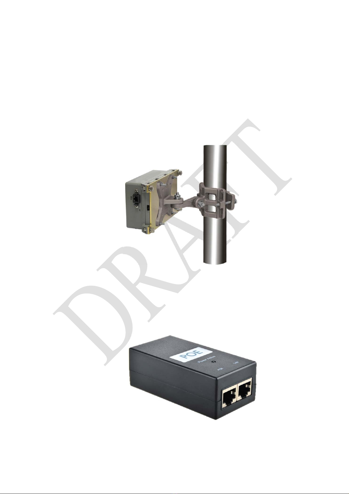
2.1.TRANSCEIVER:................................................................................................................................................4
2.2.POE(CUSTOMERSUPPLY)...............................................................................................................................4
2.3.INSTALLATIONREMOVABLEMEDIA....................................................................................................................5
3.SYSTEMMAPSINSTALLATION/SETUP..............................................................................................6
3.1.MANUALINSTALLATION...................................................................................................................................6
3.2.AUTOMATICINSTALLATION...............................................................................................................................6
4.ELM‐2114OPERATINGSYSTEMINSTALLATION..................................................................................7
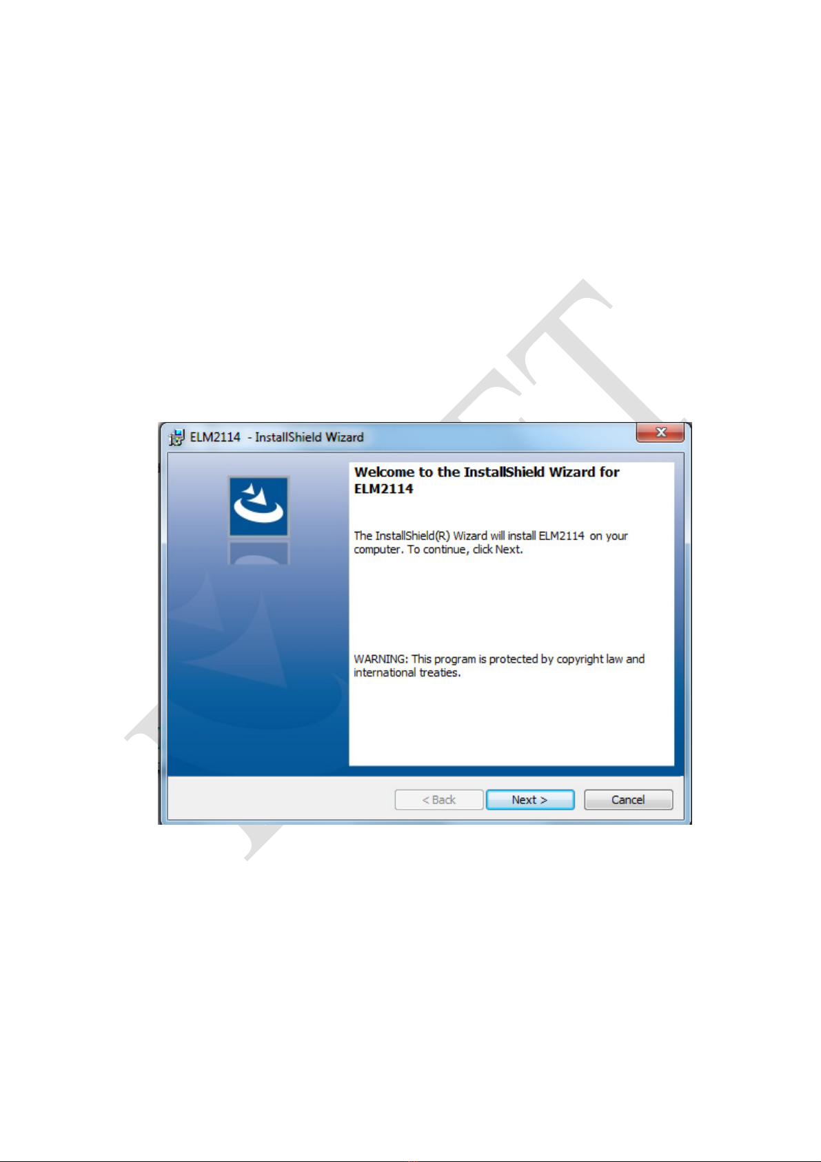
4.1.ELM2114–OPERATINGSYSTEMINSTALLATION(HMI)........................................................................................7
4.2.RADARCOMSETAPPLICATION........................................................................................................................11
5.RADARCONFIGURATIONSETUP.....................................................................................................15
5.1.SETTINGTHERADARLOCATION.......................................................................................................................15
6.MECHANICALDESCRIPTION............................................................................................................17
6.1.MECHANICALSPECIFICATION..........................................................................................................................17
6.2.SIDEVIEWANDINSTALLATIONDIRECTION..........................................................................................................18
7.MECHANICALINSTALLATIONGUIDELINES:.....................................................................................19
7.1.INSTALLATIONHEIGHT:..................................................................................................................................19
7.2.ROIOBSERVATIONREQUIREMENT:..................................................................................................................19
7.3.TWORADARSINSTALLATION‐DISTANCECALCULATION........................................................................................19
8.COMPONENTSINTERCONNECTION.................................................................................................21
9.SAFETYINSTRUCTIONS...................................................................................................................22
9.1.ELECTRICALSAFETY.......................................................................................................................................23
9.2.RADHAZSAFETY.........................................................................................................................................23
10.POWERREQUIREMENTS.................................................................................................................24
11.RECOMMENDED20[M]CABLE[CANBEPURCHASESEPARATELY]....................................................25

UNCLASSIFIED
This document contains proprietary information of ELTA System Ltd.
ELM-2114 Installation Manual Subject to Change without Notice
3
1. GENERAL
This Installation Manual describes installation procedures for the ELM-2114 Persistent
Perimeter Detection Radar.
The ELM-2114 persistent perimeter detection radar is an advanced high-resolution radar with
unique and outstanding capabilities. Featuring simultaneous multi beam technology, it
provides persistent surveillance and instantaneous target tracking over the entire region of
interest (ROI), allowing an immediate and simultaneous detection, monitoring and tracking of
all moving ground targets in the ROI, in tough weather conditions.
The main feature of the ELM-2114 is extremely low false alarm rate, crucial for perimeter
monitoring. It is equipped with a stationary (non-rotating) planar array covering (Staring at) an
azimuth sector of 90°, with detection range capabilities of (up to) 500 m meters for a moving
person, and up to 1000 m meters for moving vehicles, characterized by high reliability and
maintenance-less hardware.
Unlike most Radars, this Radar does not have a scanning (mechanical or electronic) beam but
rather covers all the area of interest simultaneously, using the Multibeam principle.
The Radar has the capability to be interface to a visual aid (day and/or night) (option) which
can be steered automatically from the display station, allowing the operator to classify targets
in the area of Interest.

UNCLASSIFIED
This document contains proprietary information of ELTA System Ltd.
ELM-2114 Installation Manual Subject to Change without Notice
4
2. KIT CONTENTS
The ELM-2114 Radar kit contains three (3) components:
2.1. Transceiver:
The transceiver module contains an RF front section and a digital circuit. The Transceiver
includes a single POE plug.
The Transceiver unit is installed on a pole, mast or a tripod, using dedicated mechanical
adapter that can be purchase separately.
Figure 1: Mechanical Adapter
2.2. POE (Customer Supply)
The Radar receives 48VDC power through a POE unit, which can be provided through
dedicated POE unit, or customer standard network equipment, which already includes POE.
Figure 2: POE

UNCLASSIFIED
This document contains proprietary information of ELTA System Ltd.
ELM-2114 Installation Manual Subject to Change without Notice
5
2.3. Installation Removable Media
The enclosed installation Removable Media contains the radar operating application.
The ELM-2114 application supported by the following Operating Systems:
Win 7 / Win 10 pro.

UNCLASSIFIED
This document contains proprietary information of ELTA System Ltd.
ELM-2114 Installation Manual Subject to Change without Notice
6
3. SYSTEM MAPS INSTALLATION / SETUP
3.1. Manual installation
The System application displays raster and vector maps.
System Maps installation requires the following steps:
Get raster maps, which are Orth-photo maps of the Geo TIFF format, uses WGS84
datum: (GeoTIFF format is georeference raster imagery, WGS84 datum is the World
Geodetic System provided in 1984) in resolution of 1 to 5 meters per pixel.
To obtain real measurements, verify that the Ortho-photograph is an aerial photograph
geometrically corrected ("orthorectified"), such that the scale is unified and it has no
distortion.
The map coverage area should be 1Km x 1Km square for the region of interest, while
the Radar placed at the corner of square and the surveillance area is within the square.
Place the map file placed in the Maps directory on your operation station.
3.2. Automatic Installation
TBD

UNCLASSIFIED
This document contains proprietary information of ELTA System Ltd.
ELM-2114 Installation Manual Subject to Change without Notice
7
4. ELM-2114 OPERATING SYSTEM INSTALLATION
The following description specifies the ELM-2114 Operation System installation.
Insert the Operating System installation media and follow the on screen installation guide
accordingly.
The installation includes two stages:
1. ELM2114 – Operating System Installation (HMI)
2. Radar Com Set Application - setting the radar network system communication
4.1. ELM2114 – Operating System Installation (HMI)
4.1.1. Welcome Screen
4.1.2. Installation Preparation screen

UNCLASSIFIED
This document contains proprietary information of ELTA System Ltd.
ELM-2114 Installation Manual Subject to Change without Notice
8
4.1.3. License Agreement
4.1.4. Operating System Installation Directory

UNCLASSIFIED
This document contains proprietary information of ELTA System Ltd.
ELM-2114 Installation Manual Subject to Change without Notice
9
4.1.5. Installation Readiness Screen
4.1.6. Installation Process Status

UNCLASSIFIED
This document contains proprietary information of ELTA System Ltd.
ELM-2114 Installation Manual Subject to Change without Notice
10
4.1.7. Installation Completion Screen
4.1.8. Uninstall

UNCLASSIFIED
This document contains proprietary information of ELTA System Ltd.
ELM-2114 Installation Manual Subject to Change without Notice
11
If the software has been installed before, the installation software provide the removal option
of the previous version, before proceeding with the new one.
4.2. Radar Com Set Application
By the end of the operating system installation, put the checkmark to launch the radar burner
application, and follow the on screen instructions, which will guide you how to set the
required network connection between the radar and the operation PC.
4.2.1. Radar to PC connection setup screen

UNCLASSIFIED
This document contains proprietary information of ELTA System Ltd.
ELM-2114 Installation Manual Subject to Change without Notice
12
4.2.2. System Subnet Detection
4.2.3. Temporary Connection Establishment

UNCLASSIFIED
This document contains proprietary information of ELTA System Ltd.
ELM-2114 Installation Manual Subject to Change without Notice
13
4.2.4. Final Connection Screen
Note: In case the application automatically started following paragraph 5.2.4, it means that the Radar
installed and configured correctly.

UNCLASSIFIED
This document contains proprietary information of ELTA System Ltd.
ELM-2114 Installation Manual Subject to Change without Notice
14
4.2.5. System Main Display
By the end of the process described above the following icons will appear on your desktop.
Double click on the RadarComSet ICON will allow you to reconfigure the radar network set up in
case that the system network was change and new set up is required.
Double click on the ICON shortcut will activate the radar operation system followed by the main
system main display screen.
Figure 3: Main Display

UNCLASSIFIED
This document contains proprietary information of ELTA System Ltd.
ELM-2114 Installation Manual Subject to Change without Notice
15
5. RADAR CONFIGURATION SETUP
5.1. Setting the Radar location
After successful system operation installation, run the application using the icon on the
desktop and Open the Radars menu appears on the BAR menu and choose the Radar
Properties option.
Figure 4: Radar Properties
5.1.1. General Field:
Leave the predefined default value with no change.
5.1.2. Location Field
Insert following data:
UTM X – The radar [UTM] latitude position
UTM Y – The radar [UTM] longitude position
UTM Zone – The zone number of the area according to the UTM's zones map
Ground Elevation - Radar height above sea level [M]
Radar elevation above ground level [M]
5.1.3. Operational

UNCLASSIFIED
This document contains proprietary information of ELTA System Ltd.
ELM-2114 Installation Manual Subject to Change without Notice
16
Insert following data:
Minimum Range
Maximum Range
Radar Azimuth – Radar azimuth relative to the north [degrees]
Frequency Band – Default value that will need to be changed in case of using several radars to
avoid interference between the radars.
Click on the Close Tab in order to save the setup data in the system.
5.1.4. North Alignment of the radar
After setting the radar to Tx On, find a significant known location reference target within the Radar ROI.
Verify that the target known geo-position location is aligned with target's location presented on the display.
If there is a mismatching, check the radar's location and azimuth settings and perform the realignment

UNCLASSIFIED
This document contains proprietary information of ELTA System Ltd.
ELM-2114 Installation Manual Subject to Change without Notice
17
6. MECHANICAL DESCRIPTION
The following Radar drawings describe the Radar mechanical dimensions that will allow the
user to design the radar mounting mechanical adapter.
6.1. Mechanical Specification
Radar Weight – 1.0 Kg (approximately)
There are 4 threading holes (for 1/4 NC Allen bolts) at the radar bottom to attach the Radar to
any mechanical adapter.
Figure 5: Mechanical Dimensions [mm]

UNCLASSIFIED
This document contains proprietary information of ELTA System Ltd.
ELM-2114 Installation Manual Subject to Change without Notice
18
6.2. Side view and installation direction
Figure6 : Radar Side View Dimensions
Tx direction

UNCLASSIFIED
This document contains proprietary information of ELTA System Ltd.
ELM-2114 Installation Manual Subject to Change without Notice
19
7. MECHANICAL INSTALLATION GUIDE LINES:
7.1. Installation height:
Between 1 to 1.5 meters and above the terrain to avoid multi pass at the radar coverage area.
7.2. ROI Observation Requirement:
180° azimuths with ± 7.5° elevation sector in front of the Radar has to be free of
objects obscuring the line of sight including cables and wires.
The Radar elevation beam shape is a 15º wide "Pencil Beam" type. This beam has 0º
squint relative to the mechanical radar elevation axis.
7.3. Two radars installation - Distance calculation
Installing two Radars for a 180sector results in a minimal detection range in the overlapping
region between the Radars. The minimal range in the overlapping region is dependent on the
distance and angle between the Radars. The distance between the two installed Radars (for
180° coverage) is calculated as:
)]45(6sin[2
Ld ,
where d is the distance between the two units, L is the minimum detection range (blind range)
and αis the deviation from 90between the Radars. is 39° < α< 45° in order to cover 180°
in azimuth, and still get overlapping between the two units at the center of the covered area.

UNCLASSIFIED
This document contains proprietary information of ELTA System Ltd.
ELM-2114 Installation Manual Subject to Change without Notice
20
Figure 7: Two Radars 1800Azimuth Installation
Table of contents
Popular Radar manuals by other brands

Endress+Hauser
Endress+Hauser Micropilot FMR66B PROFINET with Ethernet-APL Brief operating instructions

Radarsign
Radarsign TC-800 installation manual

Davis Instruments
Davis Instruments 151 Assembly instructions

AGD
AGD 306 product manual

Garmin
Garmin Varia eRTL615 owner's manual

Furuno
Furuno WR2120 Operator's manual