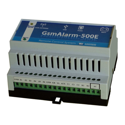
eltech GsmAlarm-500 User manual

_________________________________________________________________________________
GsmAlarm-500 Software ver. 1.15
GsmAlarm-500 (V1.15)
GSM Alarm and Remote Control System
FEATURES
•
6 inputs.
•
Up to 15 protection zones.
•
3 programmable low current outputs + 1 high current relay output.
•
5 users are notified.
•
20 programmable keypad access codes or iButton keys.
•
Possibility to transfer data to alarm monitoring station via GPRS channel by SIA DC-09 IP
protocol. AES128 encryption.
•
Possibility to connect to SmartCloud server. Monitoring and control of the system can be
performed from any computer or smart phone using a standard web browser.
•
Possibility to send information to alarm monitoring station using the Contact ID protocol
through GSM voice call.
•
Remote control using mobile phone keypad (through DTMF tones).
•
GSM JAMMING detection.
•
24 hour timer.
•
Two partial protection modes (STAY and SLEEP).
•
Possibility to divide the system into two independent partitions.
•
Possibility to connect up to 6 temperature sensors for temperature measurement.
•
Possibility to connect up to 4 keypads.
•
Info-carrying SMS showing state of each sensor, power supply voltage, GSM signal
strength.
•Programming and firmware upgrade via USB connection.
•
Remote programming over GPRS.
•
Integrated quad-band GSM module.
•Wide operating temperature range: -35 … +65ºC.

TABLE
OF
CONTENS
_________________________________________________________________________________
GsmAlarm-500 Software ver. 1.15
TABLE OF CONTENTS
1. General Information..................................................................................................................... 1
1.1. Safety Instructions ................................................................................................................... 1
1.2. Package Content.......................................................................................................................2
1.3. Introduction..............................................................................................................................3
2. Connectors and LED indicators...................................................................................................4
2.1. Zone Input terminals Z1 to Z6 .................................................................................................4
2.2. Keypad Connection Terminals GR and YL..............................................................................4
2.3. Auxiliary Power Terminal AUX .............................................................................................5
2.4. Programmable Output Terminals C1, C2 and C3.....................................................................5
2.5. BELL/SIREN Connection Terminals K1, K2 .......................................................................... 5
2.6. AC Power Terminals................................................................................................................5
2.7. BAT Connector........................................................................................................................5
2.8. External Microphone Connector............................................................................................. 5
2.9. RESET Button ......................................................................................................................... 5
3. LED Indicators..............................................................................................................................6
3.1. NETWORK: GSM Module State and Signal Strength indicator.............................................. 6
3.2. MODE: Alarm System Status Indicator...................................................................................6
4. Installation.....................................................................................................................................7
4.1. General Installation Instructions .............................................................................................. 7
4.2. Wiring Diagrams......................................................................................................................9
4.2.1. System with keypad access control................................................................................... 9
4.2.2. System with iButton access control...................................................................................9
4.2.3. Wiring diagram when the device operates in the gate control mode................................ 10
4.2.4. Ways to connect alarm zones.......................................................................................... 11
4.3. Connection of Temperature Sensors ...................................................................................... 12
5. Programming..............................................................................................................................13
5.1. General Programming Instructions ........................................................................................13
5.2. User and Alarm Monitoring Station numbers ........................................................................13
5.2.1. Programming with Standard Mobile Phone..................................................................... 14
5.2.2. Programming with SMS .................................................................................................14
5.3. Programming System Parameters with SMS .........................................................................16
5.3.1. Programming Zones........................................................................................................ 16
5.3.1.1. Parameter “A”: Input Triggering Conditions............................................................18
5.3.1.2. Parameter “M”: System State after Input Triggering................................................19
5.3.1.3. Parameter P: Dividing System into Two Partitions and Partial Arming Modes
STAY and SLEEP. Tamper Recognition.................................................................20
5.3.2. Programming of Output C1-C4 (K1, K2) and Common System Parameters
“E”, “F”, “G”, “H”, “J”, “K”, “L”, “P”, “T” ...............................................................20
5.3.2.1. Output C1-C4 (K1, K2) Operating Mode................................................................. 22
5.3.2.2. Outputs C1-C4 (K1, K2): Inverted Mode and Operating Time Units.......................23
5.3.2.3. Configuration of the Gate Control Mode..................................................................23
5.3.2.4. Parameter “E”: the Way User Is Informed About Arming/Disarming......................24
5.3.2.5. Parameter “F”: System Response to Incoming Calls and Number
of Calls in Alarm State............................................................................................. 24
5.3.2.6. Parameter “G”: SMS Delay Time in Case of Power Supply Failure ........................24
5.3.2.7. Parameter “L”: SMS Structure and SMS Password Functionality............................ 25
5.3.2.8. Parameter “P”: Splitting of the system into 2 partitions.
24 hour tamper supervision ...................................................................................... 25
5.3.3. Programming Partition Names. ......................................................................................25
5.3.4. Setting System Clock......................................................................................................26

TABLE
OF
CONTENS
_________________________________________________________________________________
GsmAlarm-500 Software ver. 1.15
5.3.5. Programming 24 Hour Timer.......................................................................................... 26
5.3.5.1. Timer Instructions....................................................................................................27
5.4. Programming the Description of Input Zone State ................................................................28
5.5. Programming User Names.....................................................................................................28
5.6. Programming SMS Password................................................................................................. 28
5.7. Programming the System using the Keypad...........................................................................29
5.7.1. Programming Access Codes............................................................................................ 30
5.7.2. User Access Code Functionality .................................................................................... 31
5.7.3. Exit Delay Time..............................................................................................................31
5.7.4. Parameter “T”: Entry Delay Time or Triggering Temperature........................................ 32
5.7.5. Parameter “A”: Input Triggering Conditions ..................................................................32
5.7.6. Parameter “M”: System State after Input Triggering....................................................... 32
5.7.7. Assignment of a Zone to a Partition. Partial Protection Modes STAY and SLEEP.
Tamper Recognition (parameter P) ...............................................................................33
5.7.8. Parameter “I”: Pulse counting Mode or temperature hysteresis....................................... 33
5.7.9. Zone Response Time....................................................................................................... 34
5.7.10. Operating Time of Outputs C1-C4 and BELL............................................................... 34
5.7.11. Operating Mode of Outputs C1-C4 and BELL..............................................................34
5.7.12. Outputs C1-C4 (K1, K2): Inverted Mode and Operating Time Units............................35
5.7.13. Parameter “E”: The Way User Is Informed About Arming/Disarming ......................... 35
5.7.14. Parameter “F”: System Response to Incoming Calls and Number
of Calls in Alarm State.................................................................................................. 35
5.7.15. Parameter “G”: Delay Time of Report SMS about the Power Supply Failure ..............36
5.7.16. Parameter “H”: Data Transfer to the Alarm Monitoring Station ................................... 36
5.7.17. Parameter “J”: System Response to Intentional GSM Jamming.................................... 36
5.7.18. Parameter “L”: SMS structure and SMS Password Functionality .................................36
5.7.19. Parameter “P”: Partitioning...........................................................................................36
5.7.20. Access Code Length (4 or 6 Digits) ..............................................................................37
5.7.21. Exit Delay Audible Indication.......................................................................................37
5.7.22. Assigning Keypad Zones............................................................................................... 37
5.7.23. Setting System Clock....................................................................................................37
5.7.24. Programming 24 Hour Timer........................................................................................38
5.7.25. Programming CONTACT ID User Account Number ...................................................38
5.7.26. Temperature Correction ................................................................................................ 39
5.7.27. The Way User is Informed about STAY or SLEEP Mode Activation .......................... 39
5.7.28. The Way User is Informed about STAY or SLEEP Mode Deactivation ...................... 39
5.7.29. Keypad Indicator StayD ...............................................................................................39
5.8. Programming iButton Keys....................................................................................................39
5.9. Programming and Diagnostics Over the Internet.................................................................... 40
6. Resetting system settings to factory defaults.............................................................................42
6.1. Manufacturer Programmed Parameters..................................................................................42
7. Data Transfer to Alarm Monitoring Station............................................................................. 43
7.1. GPRS Channel Settings .........................................................................................................43
7.2. Audio Channel Settings ......................................................................................................... 44
7.2.1. Programming CONTACT ID User Account Number ...................................................... 44
7.3. Modes Of Data Transfer To the Central Monitoring Station..................................................44
7.4. CONTACT ID Protocol Codes..............................................................................................45
8. System
Control Using the Keypad.............................................................................................46
8.1. Keypad Keys and LED Indicator Functionality .....................................................................46

TABLE
OF
CONTENS
_________________________________________________________________________________
GsmAlarm-500 Software ver. 1.15
8.1.1. [ ] Key - Extended indication mode ...........................................................................46
8.1.2. [TBL]Key - Trouble Display.......................................................................................... 46
8.1.3. [MEM]Key - Alarm Memory Display...........................................................................47
8.1.4. [BYP]Key - Bypass Programming................................................................................. 47
8.1.5. [CLEAR]Key ................................................................................................................47
8.1.6. [ENTER]Key................................................................................................................. 47
8.1.7. “~” Indicator .................................................................................................................. 47
8.1.8. “StayD” (Status) Indicator............................................................................................... 47
8.1.9. “OFF” Indicator ..............................................................................................................47
8.1.10. “ARM”, “SLEEP” and “STAY” Indicators................................................................... 48
8.2. Regular Arming ....................................................................................................................48
8.3. Stay & Sleep arming.............................................................................................................. 48
8.4. Disarming & Deactivating an Alarm ..................................................................................... 49
8.5. Panic Alarms..........................................................................................................................49
8.6. Control of Separate Partitions ...............................................................................................49
8.7. Programmable Outputs Control .......................................................................................... 49
9. System Control Using iButton Access Keys............................................................................49
10. Remote Arming & Disarming.................................................................................................. 50
11. System Operation in Alarm State............................................................................................51
12. Power Supply Monitoring........................................................................................................51
13. GSM Jamming Detection ......................................................................................................... 52
14. System Control Using DTMF and SMS Commands.............................................................. 53
15.
SmartCloud Server
...............................................................................................................56
15.1 Settings and Activation .........................................................................................................56
16. Warranty................................................................................................................................... 57
17. Technical Characteristics.........................................................................................58
18. Mounting Holes
.....................................................................................................................59

GENERAL
INFORMATION
_________________________________________________________________________________
GsmAlarm-500 Software ver. 1.15
-
1-
1. GENERAL INFORMATION
1.1. SAFETY INSTRUCTIONS
Please read and follow these safety guidelines in order to maintain safety of operators and people around.
Retain all safety and operating instructions for future reference during the whole operating lifetime of
device.
Device has two power supplies:
main and reserve
.
Main: power transformer: I: 230V 50/60 Hz; II: (16–24)V ~ 1,2 A 50/60Hz;
Reserve: 12 V 1,2 Ah battery.
DC power supply which must be approved by LST EN 60950-1 standard and
be easily accessible.
Any additional devices linked to the system GsmAlarm-500 (computer,
sensors, relays etc.) must be approved by LST EN 60950-1 standard.
External power supply can be connected to AC mains only inside installation
room with automatic 2-pole circuit breaker capable of disconnecting circuit
in the event of short circuit or over-current.
Open circuit breaker must have a gap between connections of more than 3mm
and the disconnection current 5A.
System GsmAlarm-500 is a device mounted in limited access areas. Any
system repairs must be done only by qualified, safety aware personnel. There
are no parts you can change at place in the device.
The system must be used only with approved back
-
up battery to avoid fire or
explosion hazards. Special care must be taken connecting positive and
negative battery terminals. Switching the pole terminals places is NOT
allowed.
Mains power must be disconnected before any installation or tuning work
starts. The system installation or maintenance must not be done during
stormy conditions.
If you use I security class computer for setting the parameters it must be
connected to earth.
The device is switched off by 2-pole circuit breaker and disconnecting back-up
battery connector.

GENERAL
INFORMATION
_________________________________________________________________________________
GsmAlarm-500 Software ver. 1.15
-
2-
Mains power and back-up battery must be disconnected before any
installation or tuning work starts. The system installation or maintenance
must not be done during stormy conditions.
Remote control and monitoring device GsmAlarm-500 has built-in radio transmitter operating on GSM900
and GSM1800 networks.
Do not use the device where it can cause interferences and danger.
Do not arrange the device close to medical equipment and appliances.
Do not use the device in explosive environment.
Device is not resistant to moisture, chemical materials or mechanical damage.
Don’t attempt to personally repair the system.
System label is on the top side of the device.
This symbol on the product or on its packaging means that your electrical and electronic
equipment should be disposed at the end of life separately from your household wastes.
There are separate collection systems for recycling in EU. For more information, please
contact the local authority or the dealer where you purchased the product.
The device compliance to RoHS Directive.
1.2. PACKAGE CONTENT
Main board GsmAlarm-500....................................................................Qnty 1
GSM antenna with magnetic fix and 2 m lead cable ..............................Qnty 1
Microphone ............................................................................................Qnty 1
Microphone connector ...........................................................................Qnty 1
Load resistors 1,0kΩ±5% ................................................................... Qnty 12
Load resistors 2,2kΩ±5% .....................................................................Qnty 6
Load resistors 4,7kΩ±5% .....................................................................Qnty 7
Battery connection wire..........................................................................Qnty 1
Fastening clips .......................................................................................Qnty 4
User‘s manual ........................................................................................Qnty 1

GENERAL
INFORMATION
_________________________________________________________________________________
GsmAlarm-500 Software ver. 1.15
-
3-
1.3. INTRODUTION
GsmAlarm-500 can be used for protection of houses, apartments, cottages and other buildings. In the case of
trespass of the protected zone GsmAlarm-500, depending on the programmed system operating algorithm, can
switch the siren on, call and send SMS messages to five users and transfer data to the alarm monitoring station
through GSM network. Data can be transferred directly to alarm monitoring station by Contact ID protocol
(audio channel), or can be converted to a standardized, many security service stations understandable, SIA DC-
09 IP format and transmitted via Internet (GPRS channel). It is possible to transfer data in both methods: first
try to send data via GPRS channel, if fails, use Contact ID protocol (audio channel).
User answers the call, can listen, what is going on in the unit and control the system using his mobile phone
keypad (through DTMF tones).
GsmAlarm-500 has 3 (4, if siren is not used) programmable outputs, intended for remote control of different
devices. User can turn on/off heating, ventilation or lighting systems etc, by using his mobile phone just by
typing a 2-digit code or sending SMS to the control device.
Device works perfect for remote control of automated gates, fences and electromagnetic door locks.In order to
open the gate, user calls GsmAlarm-500 number. Then GsmAlarm-500 checks the caller’s number in the list of
programmed user numbers and in the case of positive find, switches on the gate control device and cancels the
call automatically. 250 users are able to control the gate.
Up to 4 Paradox K636, K10V/H (MG10LEDV/H), K32 (MG32LED), K32LCD (MG32LCD), TM50 keypads
can be connected to GsmAlarm-500. By using the keypad users can arm or disarm the system and configure
system parameters. Following keypad LED indicators you can determine protected unit state, system mode
etc.
The system is controlled by iButton (also known as DALLAS) keys.Several control functions can be assigned
to each key. Example: a user can activate a protection mode and a controllable output by touching the contact
with the key. A user name can be assigned to each key (as well as to a keypad code) that will be indicated in
SMS messages. Up to 20 iButton keys can be programmed.
If keypad or iButton keys are not used, the system may be armed and disarmed by a simple switch or a short
free call. The alarm system is controlled exclusively from the user telephone. If the system receives a call,
coming not from the user's phone, the call is immediately interrupted and the user is sent an SMS message,
specifying the caller's phone number. The user is also informed by an SMS message about loss and restoration
of AC mains power supply.
The system answers only to the numbers programmed. If the system receives a call, coming not from the user's
phone, the call is immediately interrupted and the user is sent SMS, specifying the caller's phone number. SMS
messages are also sent to users in case of power loss and restoration.
The system has temperature measurement possibility. Up to 6 temperature sensors can be connected to
GsmAlarm-500 device. If temperature exceeds or subsides programmed range, system sends SMS to user(s),
relevant programmable output can be activated/ deactivated.
24 hour timer enables activation/deactivation of programmable output, arming or disarming, receiving SMS
messages with protected object state information on a desired time.
The system has capability to detect intentional jamming of GSM. The siren is activated upon detection of the
jamming signal, and the user is informed thereof by an SMS message about it after clearing of GSM jamming
signal. The message indicates the jamming onset time.
GsmAlarm-500 parameters may be set via a computer using the GSM alarm configuration tool GAprog. The
module is accessible via an USB port or over the internet through GPRS channel. If a computer is unavailable,
the system is set up by a keypad or SMS messages.

TERMINAL
CONNECTIONS
_________________________________________________________________________________
GsmAlarm-500 Software ver. 1.15
-
4-
2. CONNECTORS AND LED INDICATORS
`
NETW.
RESET
SIM CARD
GND Z1 Z2 Z3 Z4 Z5 C1 C2AUX
RESERVE
BATTERY
CONNECTOR
Z6 GND ACYLGR
MODE
C3 K1 K2
MICROPHONE
CONNECTOR
M-M+
GSM MODULE
SIM CARD
SLOT
GSM ANTENNA
CONNECTOR
(SMA)
USB
- +
(C4)
SYSTEM STATUS
LED INDICATORS
BATT
Connection terminals and LED indicators
2.1. ZONE INPUT TERMINALS “Z1” to “Z6”
Inputs Z1-Z6 are used to connect alarm detectors or temperature
sensors KTY81-110 (PHILIPS).
The zones are designed to work with End of Line (EOL) resistors
of 2,2kΩ(and 4,7kΩin ATZ mode, see Ch. 4.2.4). The system
becomes triggered both when the input circuit is broken as well as
when it is short-circuited.
The inputs can operate in a non EOL mode (see Ch. 4.2.4). In this
case EOL resistor in not required. The system is triggered after
breaking or short-circuiting of the input circuit (depending on the
programmed "active" level).
Equivalent diagram of zone input
2.2. KEYPAD CONNECTION TERMINALS “GR” and “YL”
Use GR, YL, GND and AUX terminals to connect PARADOX K636, K10V/H (MG10LEDV/H), K32
(MG32LED) or K32LCD (MG32LCD) keypad. These terminals can also be used for connection of
the iButton key reader.
2.2k
+5V
GND
Z
Processor

TERMINAL
CONNECTIONS
_________________________________________________________________________________
GsmAlarm-500 Software ver. 1.15
-
5-
2.3. AUXILIARY POWER TERMINAL “AUX”
The auxiliary power supply can be used to power motion detectors and other devices requiring 12
VDC. “AUX” is short-circuit-protected. Max load current is 1.3 A.
2.4. PROGRAMMABLE OUTPUT TERMINALS “C1”, “C2” and “C3”
The programmable output is a 150 mA maximum switch to ground. A 33 ohm
current limiting resistor is connected in series. A small relay, a buzzer or other
DC operated device may be connected between the “AUX” (positive) terminal
and the “C” (switched negative) terminal on the main board.
Relays with 12V operating voltage and current not exceeding 150 mA max, are
recommended for device control.
Output operating modes are described in Ch. 5.3.2.1
Equivalent diagram of C output
2.5. BELL/SIREN CONNECTION TERMINALS “K1” and “K2”
These terminals are relay contacts of the programmable output C4. K1 and K2 are used to connect
audio siren or extra-commutated device.
Commutated current may reach 5 A max.
2.6. “AC” POWER TERMINALS
Use a 16-24 VAC transformer with a minimum 40 VA rating to supply AC power to the
GsmAlarm-500.
2.7. “BATT” CONNECTOR
Use this connector to connect the backup battery. Max capacity of the backup battery is 1,2 Ah.
Voltage: 12 VDC.
2.8. EXTERNAL MICROPHONE CONNECTOR
This connector is used to connect an external microphone. Connect white wire to contact M+, black –
to M-. If wire of the microphone is long (over 2 m), it is recommended to use shielded twisted pair
cable. Connect shield to GND contact. In order to avoid interference install microphone as far as
possible from GSM antenna. The microphone turns on automatically in speech mode.
2.9. RESET BUTTON
RESET button is used to restore factory default settings (see. Ch. 6).
C
33
GND

LED
INDICATORS
_________________________________________________________________________________
GsmAlarm-500 Software ver. 1.15
-
6-
3. LED INDICATORS
3.1. NETWORK: GSM MODULE STATE AND SIGNAL STRENGTH INDICATOR
Indicator state Explanation
Out. GSM module is not in use. No power supply or
system failure.
Continuously On.
There is no GSM operator network registration.
Possible causes: SIM card PIN code request is not
deactivated, antenna not connected or poor network
connection quality.
Blinking more frequently than once a
second. GSM module is in use: outgoing call or SMS is
being sent.
Blinks 5 times, short break after.
Very good signal.
Blinks 4 times, short break after. Good signal.
Blinks 3 times, short break after. Satisfactory connection.
Blinks 2 times, short break after. Weak connection.
Blinks once, short break after. Poor connection.
3.2. MODE: ALARM SYSTEM STATUS INDICATOR
Indicator state Explanation
Out.
No power supply or system failur
e.
Continuously On.
System is operative, disarmed, no zone sensors have
been triggered.
On with short breaks. System is operative, disarmed, but one or more zone
sensors have been triggered.
Blinking with low frequency (once in
2-3 sec.). System is armed.
Blinking more frequently than once a
second. System is in alarm state.
Blinking very rapidly for
2
-
3 sec.
SMS instruction or
DTMF command
receipt
confirmation.

INSTALLATION
_________________________________________________________________________________
GsmAlarm-500 Software ver. 1.15
-
7-
4. INSTALLATION
4.1. GENERAL INSTALLATION INSTRUCTIONS
According to manufacturer recommendations, hire qualified security system specialist (or company)
to perform system installation works. Self-dependent installation of the system can be performed
only if person possess basic knowledge in electricity and electronics,otherwise device might be
irrecoverably damaged.
System should be assembled in metal housing 7TRP20 as recommended.
Housing
fixture holes
4x5mm SAUGIKLIS
Metal housing (7/TRP20)
RED BLUE
POWER SUPPLY
TRANSFORMER
T 0.16A LSTEN 60950
(TRP 20/01)
BACKUP
BATTERY
AC 12V 1.3Ah
(CT1.3-12)
-
AC 18VAC 230V
+
GSM antenna
GSM
antenna
connector
NETW.
RESET
GND Z1 Z2 Z3 Z4 Z5 C1 C2AUXZ6 GND ACYLGR
MODE
C3 K1 K2
MICROPHONE
CONNECTOR
M-M+
GSM MODULE
SIM CARD
USB - +
(C4)
HOLE FOR CABLES
GSMA-500
+
+
-
Antenna cable
Board
fixture holes
4 x 3.5 mm
+
-
> 6 cm.
Recommended layout of system elements in 7/TRP20 type housing
Use double isolated cable 3x0,75 mm
2
for 230V power supply. Circuit breaker or other surge
protection device should be installed in the 230V power line.
Antenna is fixed on the top of outer side of metal housing.

INSTALLATION
_________________________________________________________________________________
GsmAlarm-500 Software ver. 1.15
-
8-
It is recommended to use standard motion (e.g., SRP-300) and fire (e.g., EA318-2) sensors in alarm
system. Use standard 6-8 wired single core cable designed for installation of alarm systems. Siren
DC12V 500mA (e.g., Odyssey 1E) is recommended for sound alarm, use double isolated cable
2x0,75 mm
2
to connect it to the system. Backup battery must be PB-acid (e.g., CT1.2-12).
It is recommended to install remote control relays into sockets (e.g., F95913) which can be easily
fixed to metal housing. Operating current of relay coil cannot exceed 150mA max (e.g., F4031-12).
Relays are selected depending on desirable commutative voltage and current.
Connection according to the wiring diagram presented in Chapter 4.2.1 is recommended, if the
system is controlled by a keypad. Up to 4 Paradox K636, K10V/H (MG10LEDV/H), K32
(MG32LED), K32LCD (MG32LCD) or TM50 keypads can be connected to GsmAlarm-500. Each of
the said keypads has a single keypad zone (the blue wire). Use of keypad zones is recommended for
connection of magnetic door sensors. Activation of a keypad zone is described in Chapter 5.7.22 In
case of TM or TM50 keypad, it is recommended to switch off the StayD indication (see Ch. 5.7.29).
On other types of keypads, StayD indicator is on, when all zones are closed and the protection mode
can be activated.
Connection according to the wiring diagram presented in Chapter 4.2.2 is recommended, if the
system is controlled by iButton (DALLAS) keys DS1990A or a simple switch. Short beeps are
generated by an ancillary buzzer while exiting a room and a continuous sound, after entering the
room. Any buzzer with power supply of 12 V DC and maximum operating current of 100 mA may
be used (e.g., BPT-23CXW-1). The system status LED indicator woks in sync with the “MODE”
indicator (see Ch. 3.2). The state of this indicator allows identification of the alarm system status and
verification of closure of all protected zones before arming the alarm system. The status indicator
should be mounted indoors in a well visible location. The reader DS9092LED of iButton keys is
equipped with an embedded LED indicator that can be used as system status indicator.
If the system is controlled by an ON/OFF switch, the system is armed by opening the switch contacts
and disarmed by closing the contacts.
Input circuits are connected according to corresponding diagram provided in Chapter 4.2.4 It is
recommended to turn off zones that aren‘t used – to change value of A parameter to “A00” (see Ch.
5.3.1.1).
A SIM card needed for GsmAlarm-500 operating, you may acquire it from any GSM service
provider. Before inserting SIM card into GsmAlarm-500 SIM card slot set PIN code request off. It
can be performed simply inserting SIM card into any standard mobile phone and following certain
phone user manual instructions. Verify that the SMS card is operational: try calling and sending an
SMS from the phone itself.
After finishing installation, insert SIM card into GsmAlarm-500 SIM card slot, turn system power on,
then wait until LED “NETWORK” will start to flash and LED “MODE” will be constantly alight. In
case “NETWORK” is constantly alight, check if SIM card‘s PIN code request is off and GSM
antenna is connected. GSM signal quality can be evaluated according the blinking frequency of
“NETWORK” indicator. Connection is very good if it blinks 5 times with short break after.
“NETWORK” indicator blinking fewer times, indicates weaker connection. System works in steady
state if indicator blinks 3-5 times. Position of GSM antenna might be changed in order to improve
signal quality.
Perform system programming when the system is disarmed. Protected zones must be closed
(indicator “MODE” constantly alights). Detailed programming description can be read in Chapter 5.

INSTALLATION
_________________________________________________________________________________
GsmAlarm-500 Software ver. 1.15
-
9-
4.2. WIRING DIAGRAMS
4.2.1. SYSTEM WITH KEYPAD ACCESS CONTROL
Keypad. zone 1
GND Z1 Z2 Z3 Z4 Z5 ACGND
Power supply transformer
Additional relays for
extra-commutated devices
Z6 C2C1 C3YLGR AUX
AC 16-24V
~1.2 A
Keypad No.1
GREEN
YELLOW
BLACK
RED
BLUE
1k
GREEN
YELLOW
BLACK
BLUE
Keypad No.2 RED
1k
Keypad zone 2
-
+
Power supply for
motion or fire
detectors
K1 K2
Siren
4.7k
2-wire smoke detector
EA318-2
-
-
+
+
AC 230V
0.16A
Fuse
5
2
4.2.2. SYSTEM WITH iBUTTON ACCESS CONTROL
DS9092LED
GND Z1 Z2 Z3 Z4 Z5 ACGND
Power supply transformer
Additional
relay
Z6 C2C1 C3YLGR AUX
AC 16-24V
~1.2 A
-
+
Power supply
for motion or
fire detectors
K1 K2
Siren
4.7k
2-wire smoke detector
EA318-2
-
-
+
+
BPT-23CXW-1
-
+
Buzzer
System status
indicator
iButton key
reader
Switch ON/OFF
(if iButton key is not used)
I-Button
WH.
GREY
YEL.
GRN.
AC 230V
0.16A
Fuse
5
2

INSTALLATION
_________________________________________________________________________________
GsmAlarm-500 Software ver. 1.15
-
10-
4.2.3. WIRING DIAGRAM WHEN THE DEVICE OPERATES IN THE GATE CONTROL
MODE
DS9092LED
GND Z1 Z2 Z3 Z4 Z5 ACGND
AC 230V
Power supply
transformer
Z6 C2C1 C3YLGR AUX
AC 16-24V
~1.2 A
K1 K2
System status
indicator
iButton key
reader
I-Button
WH.
GREY
YEL.
GRN.
F 160 mA
Relay 1 Relay 2 Relay 3
DC 12V 150mA max
Additional relay
In this case, the power supply transformer and the backup battery are connected according to the
wiring diagram of the premise security system (see Ch 4.1). The gate control system (operating
output C4) is connected to terminals K1 and K2.
Outputs C1, C2, and C3 can also be used for gate control. In that case, remote control relays are
connected to the terminal AUX and the said output terminals. Gate control systems are connected to
the commutated contacts of the relays. In this case, individual operated outputs could be assigned to
different telephone numbers (see Ch 5.2.1). The system is controlled by a DALLAS key when
necessary. Programming of gate control mode of the device is described in Chapter 5.3.2.2

INSTALLATION
_________________________________________________________________________________
GsmAlarm-500 Software ver. 1.15
-
11-
4.2.4. WAYS TO CONNECT ALARM ZONES
N.C.
2.2K
Z
GND
N.O.
2.2K
ZGNDGNDZ Z
N.C.
N.O
.
GND
A1Y
Without EOL resistor With EOL
Resistor (A3Y)
TAMPER
WITCH
1K
ZGND
2.2K
N.C.
N.C. With EOL, With Tamper
Recognition (A2Y+PX4)
A2Y
TAMPER
WITCH
1K
ZGND
2.2K
N.O.
N.O. With EOL, With Tamper
Recognition (A1Y+PX4)
4.7K
ZGND
2.2K
N.C.
ATZ Parallel (A4Y)
N.C.
Z01 ... Z06
Z07...Z15
TAMPER
WITCH
1K
ZGND
1K
N.C. (N.O.)
ATZ With Tamper Recognition N.C. (A4Y+PX4)
ATZ With Tamper Recognition N.O. (A6Y+PX4)
2.2K
N.C. (N.O.)
Z01 ... Z06 Z07...Z15
N.O. + TAMPER N.C. + TAMPER
N.O. N.C. EOL
ATZ N.C. (N.O.) + TAMPER ATZ Parallel
1
34
56
NC: normally closed contacts. NO: normally open contacts.
A1Y-A6Y: zone operating modes, parameter “A” (see Chapter 5.3.1.1).
GsmAlarm-500 has 6 inputs Z1...Z6, corresponding to the zone numbers Z01...Z06. If 6 zones are
sufficient for protection of the object, the wiring diagrams 1, 2, 3 or 4 may be deployed. Load
resistors are mounted in the housing of an alarm sensor or a magnetic contact at the furthest point of
the connecting cable.
When wiring diagrams 3 or 4 are deployed, the tamper recognition mode should be activated (see Ch.
5.3.1.3). A fault signal is generated and, consequently, an alarm is generated upon cutting or short-
circuiting the line. When 24 hour tamper supervision mode is activated (see Ch. 5.3.2.8), the alarm is
generated with both armed and disarmed modes.
If 6 zones are insufficient, the wiring diagrams 5 and 6 may be deployed. In this case, one input can
control two zones.
If a 2-wire fire sensor is connected to the programmable output C3, the zone Z07 should be set as an
additional fire zone (A5Y mode, see Ch. 5.3.1.1), and the output C3 should work in the following
mode: M01T05 inverted (see Ch. 5.3.2 and Ch. 5.7.11). A load resistor of 4,7kΩalso should be
used.

INSTALLATION
_________________________________________________________________________________
GsmAlarm-500 Software ver. 1.15
-
12-
A triggered fire sensor is switched off with an SMS message or a DTMF/keypad command for C3
output (see Ch. 14).
4.3. CONNECTION OF TEMPERATURE SENSORS
GsmAlarm-500 has temperature measurement possibility. Up to 6 temperature sensors KTY81-110
(PHILIPS) can be connected to the GsmAlarm-500.
2 pin terminal block
GsmAlarm-500
GND Z
Temperature sensor
KTY81-110
PHILIPS
Input
Fixing hole
Shield
In order to minimize influence of external interferences and measurement error, it is recommended to
use shielded twisted pair cable 0.5 mm². Shield is connected to ground wire only in one end, close to
GsmAlarm-500 board. Use 2 pins terminal block with a fixing hole for temperature sensor fastening.
Parameter “A” must be changed in order to activate temperature measurement mode. (see Ch.
5.3.1.1). Input parameter T defines zone triggering temperature. The triggering temperature can be
programmed in -40 ºC ... +99 ºC rage (T-50 … T99) by SMS (see. Ch. 5.3.1) or -40 ºC … +120 ºC
by computer. Using the keypad temperature can be programmed only in 0 … +99 ºC range. The
temperature difference, at which triggered zone returns to primary state (hysteresis) complies with
the parameter I (see. Ch. 5.3.1).
In temperature measurement mode input operates the same as in protection mode, i.e. all operating
modes are valid with two exceptions:
a) No entry delay in A80 A90, system generates alarm instantly, after temperature reaches
programmed value (see Ch. 5.3.1.1);
b) No prohibition for arming, i.e. user can activate armed mode although temperature
measurement zone has been triggered.
Recommended values of parameter M: M40 or M00 (see Ch. 5.3.1.2). In first case, if the system is in
armed mode and temperature reaches programmed value, user receives SMS message (siren will not
turn on and system will not dial).
If two triggering temperatures are required, an extended zone (Z7…Z15) may be assigned to the
main temperature zone (Z1…Z6). The A8Y mode or A9Y mode should be activated for the ancillary
temperature zone (see Ch. 5.3.1.1). The extended temperature zone operates according to the
temperature measured by the main temperature zone. The number of the main temperature zones
should correspond to the number of the extended temperature zones.
In order to receive information about the temperature, send GsmAlarm-500 the following SMS (see
chapter 14):
A
A
A
A
A
A
A
A
9
8
*

PROGRAMMING
_________________________________________________________________________________
GsmAlarm-500 Software ver. 1.15
-
13-
5.
PROGRAMMING
5.1. GENERAL PROGRAMMING INSTRUCTIONS
It is recommended to perform the system setup and tuning by a computer via USB port, using the
GSM alarm configuration tool GAprog. The GsmAlarm-500 main board is connected to the
computer with a standard USB A-B cable. The configuration tool is downloadable from the website
of the manufacturer: www.eltech.lt.
The GSM alarm configuration tool GAprog allows setting up of the system over the internet (see Ch.
5.9).
If a computer is unavailable, the system is set up by a keypad or SMS messages.
GsmAlarm-500 parameters can be divided into two groups. First group – user phone numbers which
are stored in SIM card memory. User phone numbers can be programmed by using standard mobile
phone of any type (see Ch. 5.2.1) or remotely, sending SMS message with the phone numbers of
users to GsmAlarm-500 (see Ch. 5.2.2).
Second group – parameters, defining system operating algorithms, names of protected zones and
programmable outputs. These parameters are stored in the memory block of GsmAlarm-500 device.
The parameters of the system can be programmed by sending SMS message (see Ch 5.3) or by using
Paradox keypad (see Ch. 5.7).
It is recommended to change the SMS password at the end of programming (see Ch. 5.6).
5.2. USER AND ALARM MONITORING STATION NUMBERS
If GsmAlarm-500 is used for protection, five user numbers can be programmed: ALRNR1, ALRNR2,
ALRNR3, ALRNR4 and ALRNR5, and two alarm monitoring station numbers can also be
programmed: CIDNR1, CIDNR2. Users can arm/ disarm the system, calls will be directed and SMS
messages will be sent to these users. If only one user exists, he must be programmed under ALRNR1.
GsmAlarm-500 will send SMS messages to this specific user in case of main power supply loss or if
an unknown number calls the system. If armed mode is turned on or off with the single touch of the
keypad or by turning the switch ON/OFF (if the keypad is not used) control dials and SMS messages
are also directed to the first user. Other four user numbers are not obligatory.
In case GsmAlarm-500 is used only for gate control it is not necessary to program ALRNR1-
ALRNR5. Up to 250 user numbers, with the possibility to control the outputs C1, C2, C3, C4 and
BELL with a short call, can be programmed in this case. Any name can be ascribed to user. Output
operating mode has to be M04 or M05 (see Chapter 5.3.2.1).

PROGRAMMING
_________________________________________________________________________________
GsmAlarm-500 Software ver. 1.15
-
14-
5.2.1. PROGRAMMING WITH STANDARD MOBILE PHONE
Insert SIM card into a standard mobile phone. Enter user name into SIM card number book using
capital letters e.g. ALRNR1 and corresponding phone number. We recommend enter the number with
international code. (E.g. +370...).
If GsmAlarm-500 is used for gate control, number of extra user numbers can be as large as fits into
the SIM card (up to 250). Any name can be assigned to extra user. Also the user number can be
assigned to control only the selected output. In this case, the controlled output name (C1, C2, C3 or
C4) must be included in the user name, e.g.: JOHN-C1, USER01-C2, USER128-C4 and similar.
There is a possibility to control each output by one touch command (pushing one button on the cell
phone keypad). In this case C0 must be included in the user name (e.g. PETER-C0). In this case the
system answers an incoming call immediately and the user has half minute to press the button on his
cell phone. The button [1] activates the output C1, [2]: C2, [3]: C3 and [4]: C4. Call is automatically
terminated after activation of the output or after half minute (if nothing is done).
When programming alarm monitoring station number you must use capital letters and enter name:
CIDNR1 (CIDNR2) and number (numbers) of alarm monitoring station.
Important!
It‘s important to note that while programming SIM card memory should be active (not phone
memory). Otherwise the user number will be recorded in the mobile phone memory used for
programming and the SIM card will remain empty.
After having programmed all user numbers, it is recommended to check whether SMS service center
number is programmed. Simplest way to check: send any SMS from the phone used for
programming. If it is sent successfully we can be sure that SMS centre number has been programmed
correctly. Otherwise, program SMS center number following the mobile phone’s user manual. SMS
center number can be learnt from GSM service provider.
After completion of programming and checking whether SIM card PIN code request is switched off,
take the SIM card off from the mobile phone and insert it into GsmAlarm-500 SIM card slot.
5.2.2. PROGRAMMING WITH SMS
In order to program the main user numbers, send the following SMS from any mobile phone into
GsmAlarm-500:
A
A
A
A
A
A
A
A
A
L
R
N
R
1
: +
3
7
0
6
1
2
3
4
5
6
7
8
9
A
L
R
N
R
2
:
+
3
7
0
6
1
2
3
4
5
6
7
8
9
A
L
R
N
R
3
: +
3
7
0
6
1
2
3
4
5
6
7
8
9
A
L
R
N
R
4
: +
3
7
0
6
1
2
3
4
5
6
7
8
9
A
L
R
N
R
5
: +
3
7
0
6
1
2
3
4
5
6
7
8
9
C
I D
N
R
1
: +
3
7
0
6
1
2
3
4
5
6
7
8
9
C
I D
N
R
2
: N
AAAAAAAA: eight digit alphanumeric SMS password, which is obligatory in the beginning of
each SMS. Manufacturer-programmed password is AAAAAAAA. User can change the password on
his own desire (see Ch. 5.6). The password may be omitted, if is disabled (see Ch. 5.3.2.7).
ALRNR1 ... ALRNR5: -user numbers.
CIDNR1, CIDNR2: - alarm monitoring station numbers.

PROGRAMMING
_________________________________________________________________________________
GsmAlarm-500 Software ver. 1.15
-
15-
Important:
a) No characters/spaces can be used before the password;
b) No spaces are allowed before and after the colon;
c) Spaces must follow the password and each phone number;
d) It is recommended to enter user numbers with international code (e.g. +123…).
It is not necessarily to send all user numbers. e.g., in order to programme only the first user number,
send the following SMS:
A
A
A
A
A
A
A
A
A
L
R
N
R
1
:
+
3
7
0
6
1
2
3
4
5
6
7
8
9
Receipt and decrypting of the SMS by GsmAlarm-500 is confirmed by blink of indicator MODE.
The phone, which has sent the programming SMS, immediately receives a confirming SMS with
programmed numbers.
In order to delete unnecessary number, send the following SMS:
A
A
A
A
A
A
A
A
A
L
R
N
R
2
:
N
Number ALRNR2 is deleted; user receives SMS with programmed numbers. In order to replace one
number with another, no separate instruction for deletion needs to be sent.
In order to receive SMS with programmed numbers ALRNR1 ... ALRNR5, send GsmAlarm-500
the following SMS:
A
A
A
A
A
A
A
A
N
R
I N
F
O
Extra user numbers (only for gate control) are programmed by sending the following SMS:
A
A
A
A
A
A
A
A
A
D
D
N
R
:
+
3
7
0
1
2
3
4
5
6
7
8
9
1
A
D
D
N
R
:
+
3
7
0
7
0
1
2
3
4
5
6
7
8
9
2
A
D
D
N
R
: +
3
7
0
1
2
3
4
5
6
7
8
9
3
ADDNR: – new number programming instruction.
+3701234567891 – new user number.
If the numbers programmed successfully, the user, who sent the message, receives SMS with newly
programmed number. In this case the confirmation message will be:
USER1:+3701234567891 USER2:+3701234567892 USER3:+3701234567893
USER1 – name, assigned to the new number.
If a short call controls several outputs, an additional number may be assigned only to a single output.
In this case, the programming message is the following:
A
A
A
A
A
A
A
A
A
D
D
N
R
- C
1
: +
3
7
0
1
2
3
4
5
6
7
8
9
1
A
D
D
N
R
-
C
2
: +
3
7
0
1
2
3
4
5
6
7
8
9
2
A
D
D
N
R
- C
3
: +
3
7
0
1
2
3
4
5
6
7
8
9
3
A
D
D
N
R
- C
4
: +
3
7
0
1
2
3
4
5
6
7
8
9
4
The first number controls only the output C1, the second, C2, the third, C3, the fourth, C4 (K1, K2).
To control any output by one-touch command, write: ADDNR-C0:+370123456789.
Up to 8 user numbers might be programmed with one SMS message.

PROGRAMMING
_________________________________________________________________________________
GsmAlarm-500 Software ver. 1.15
-
16-
In order to delete the extra user number, send to GsmAlarm-500 the following message:
A
A
A
A
A
A
A
A
D
E
L
N
R
: +
3
7
0
1
2
3
4
5
6
7
8
9
1
D
E
L
N
R
:
+
3
7
0
1
2
3
4
5
6
7
8
9
2
D
E
L
N
R
: +
3
7
0
1
2
3
4
5
6
7
8
9
3
Specified numbers will be deleted and user receives the confirming SMS:
DELETED:+3701234567891 DELETED:+3701234567892 DELETED:+3701234567893
Up to 8 user numbers might be deleted with one SMS message.
In order to receive SMS message indicating all programmed numbers, following message must be
sent to GsmAlarm-500:
A
A
A
A
A
A
A
A
N
R
L
I
S
T
User receives one or more SMS messages with all programmed numbers listed.
Note! Up to 8 user numbers can be sent in one SMS message. If 250 numbers are programmed
GsmAlarm-500 will send 32 SMS messages!
5.3. PROGRAMMING SYSTEM PARAMETERS WITH SMS
All GsmAlarm-500 input and output operating modes, delay times and names can be programmed
with the help of SMS. First, it is recommended to receive SMS with programmed parameters and
then to send the same SMS with corrected parameters back to GsmAlarm-500.
5.3.1. PROGRAMMING ZONES
In order to receive SMS with zone Z1 - Z15 parameters, send GsmAlarm-500 the following SMS:
A
A
A
A
A
A
A
A
Z
P
A
R
A
M
SMS can be sent from any GSM phone, not necessarily the user’s. GsmAlarm-500 confirms
receiving the message with frequent blinking of MODE indicator and sends four SMS messages
including input parameters Z1- Z15. First message contains Z1 – Z4 parameters, second – Z5 – Z8,
third – Z9 – Z12 and Z13 - Z15 parameters in fourth SMS message. Received message with input Z1
– Z4 parameters will look as follows:
AAAAAAAA Z01:A30M70P10I06T20 Zone1, Z02:A30M70P10I06T00 Zone2,
Z03:A30M70P10I06T00 Zone3, Z04:A30M70P10I06T00 Zone4,
AAAAAAAA: - password.
Z01 - zone input number.
A30 - parameter defines operating mode of the corresponding input (see Ch. 5.3.1.1).
M70 - parameter defines system response to the violation of protected zone and which users are
informed if certain zone sensors are triggered (see Ch. 5.3.1.2).
Table of contents
Other eltech Security System manuals
Popular Security System manuals by other brands
Velleman
Velleman HAM200 user manual
HomeMatic
HomeMatic HmIP-ASIR-O Mounting instruction and operating manual

O.Y.L. Technology
O.Y.L. Technology AX1 LED user manual
MSA
MSA SMC 2001-00 operating manual
Honeywell Home
Honeywell Home Lynx 5210 Quick reference guide
Siemens
Siemens SIRIUS 8WD42 operating instructions
