Eltek MultiCharger 1500 Manual
Description and Operating Instructions
MultiCharger 1500
12V/100A...24V/50A
Read instructions carefully before use!
All rights reserved in relation to legislation on copyright and unfair competition. This product description and these operating instructions
may not be copied, reproduced or made accessible to third parties without our prior written consent.
Page 1


IMPORTANT SAFETY INSTRUCTIONS
1. SAVE THESE INSTRUCTIONS
This manual contains important safety and operating instructions for battery charger model
MultiCharger 1500.
2. Do not expose charger to rain or snow.
3. Use of an attachment not recommended or sold by the battery charger manufacturer may result
in a risk of fire, electric shock, or injury to persons
4. To reduce risk of damage to electric plug and cord, pull by plug rather than cord when
disconnecting charger.
5. An extension cord should not be used unless absolutely necessary. Use of improper extension
cord could result in a risk of fire and electric shock. If extension cord must be used, make sure:
a) That pins on plug of extension cord are the same number, size, and shape as those
of plug on charger;
b) That extension cord is properly wired and in good electrical condition; and
c) That wire size is large enough for ac ampere rating of charger.
6. Do not operate charger with damaged cord or plug - replace the cord or plug immediately.
7. Do not operate charger if it has received a sharp blow, been dropped, or otherwise damaged in
any way; take it to a qualified serviceman.
8. Do not disassemble charger; take it to a qualified serviceman when service or repair is required.
Incorrect reassembly may result in a risk of electric shock or fire.
9. To reduce risk of electric shock, unplug charger from outlet before attempting any maintenance
or cleaning. Turning off controls will not reduce this risk.
10. WARNING - RISK OF EXPLOSIVE GASES.
a) WORKING IN VICINITY OF A LEAD-ACID BATTERY IS DANGEROUS. BATTERIES
GENERATE EXPLOSIVE GASES DURING NORMAL BATTERY OPERATION. FOR
THIS REASON, IT IS OF UTMOST IMPORTANCE THAT EACH TIME BEFORE USING
YOUR CHARGER, YOU READ THIS MANUAL AND FOLLOW THE INSTRUCTIONS
EXACTLY.
b) To reduce risk of battery explosion, follow these instructions and those published by
battery manufacturer and manufacturer of any equipment you intend to use in vicinity of
battery. Review cautionary marking on these products and on engine.
11. PERSONAL PRECAUTIONS
a) Someone should be within range of your voice or close enough to come to your aid when
you work near a lead-acid battery.
b) Have plenty of fresh water and soap nearby in case battery acid contacts skin, clothing,
or eyes.
c) Wear complete eye protection and clothing protection. Avoid touching eyes while working
near battery.
d) If battery acid contacts skin or clothing, wash immediately with soap and water. If acid
enters eye, immediately flood eye with running cold water for at least 10 minutes and get
medical attention immediately.
e) NEVER smoke or allow a spark or flame in vicinity of battery or engine.
Page 3

f) Be extra cautious to reduce risk of dropping a metal tool onto battery. It might spark or
short-circuit battery or other electrical part that may cause explosion.
g) Remove personal metal items such as rings, bracelets, necklaces, and watches when
working with a lead-acid battery. A lead-acid battery can produce a short-circuit current
high enough to weld a ring or the like to metal, causing a severe burn.
h) Use charger for charging a LEAD-ACID battery only. It is not intended to supply power to
a low voltage electrical system other than in a starter-motor application. Do not use
battery charger for charging dry-cell batteries that are commonly used with home
appliances. These batteries may burst and cause injury to persons and damage to
property.
i) NEVER charge a frozen battery.
12. PREPARING TO CHARGE
a) If necessary to remove battery from vehicle to charge, always remove grounded terminal
from battery first. Make sure all accessories in the vehicle are off, so as not to cause an
arc.
b) Be sure area around battery is well ventilated while battery is being charged. Gas can be
forcefully blown away by using a piece of cardboard or other non metallic material as a
fan.
c) Clean battery terminals. Be careful to keep corrosion from coming in contact with eyes.
d) Add distilled water in each cell until battery acid reaches level specified by battery
manufacturer. This helps purge excessive gas from cells. Do not overfill. For a battery
without cell caps, carefully follow manufacturer’s recharging instructions.
e) Study all battery manufacturers’ specific precautions such as removing or not removing
cell caps while charging and recommended rates of charge.
f) Determine voltage of battery by referring to car owner’s manual and make sure that
output voltage selector switch is set at correct voltage. If charger has adjustable charge
rate, charge battery initially at lowest rate.
13. CHARGER LOCATION
a) Locate charger as far away from battery as dc cables permit.
b) Never place charger directly above battery being charged; gases from battery will
corrode and damage charger.
c) Never allow battery acid to drip on charger when reading gravity or filling battery.
d) Do not operate charger in a closed-in area or restrict ventilation in any way.
e) Do not set a battery on top of charger
14. DC CONNECTION PRECAUTIONS
a) Connect and disconnect dc output clips only after setting any charger switches to off
position and removing ac cord from electric outlet. Never allow clips to touch each other.
b) Attach clips to battery and chassis as indicated in 15(e), 15(f), 16(b), and 16(d).
15. FOLLOW THESE STEPS WHEN BATTERY IS INSTALLED IN VEHICLE. A SPARK NEAR
BATTERY MAY CAUSE BATTERY EXPLOSION. TO REDUCE RISK OF A SPARK NEAR
BATTERY:
a) Position AC and DC cords to reduce risk of damage by hood, door, or moving engine
part.
b) Stay clear of fan blades, belts, pulleys, and other parts that can cause injury to persons.
c) Check polarity of battery posts. POSITIVE (POS, P, +) battery post usually has larger
diameter than NEGATIVE (NEG, N,-) post.
d) Determine which post of battery is grounded (connected) to the chassis. If negative post
is grounded to chassis (as in most vehicles), see (e). If positive post is grounded to the
chassis, see (f).
Page 4

e) For negative-grounded vehicle, connect POSITIVE (RED) clip from battery charger to
POSITIVE (POS, P, +) ungrounded post of battery. Connect NEGATIVE (BLACK) clip to
vehicle chassis or engine block away from battery. Do not connect clip to carburettor,
fuel lines, or sheet-metal body parts. Connect to a heavy gage metal part of the frame or
engine block.
f) For positive-grounded vehicle, connect NEGATIVE (BLACK) clip from battery charger to
NEGATIVE (NEG, N, -) ungrounded post of battery. Connect POSITIVE (RED) clip to
vehicle chassis or engine block away from battery. Do not connect clip to carburettor,
fuel lines, or sheet-metal body parts. Connect to a heavy gage metal part of the frame or
engine block.
g) When disconnecting charger, turn switches to off, disconnect AC cord, remove clip from
vehicle chassis, and then remove clip from battery terminal.
h) See operating instructions for length of charge information.
16. FOLLOW THESE STEPS WHEN BATTERY IS OUTSIDE VEHICLE. A SPARK NEAR THE
BATTERY MAY CAUSE BATTERY EXPLOSION. TO REDUCE RISK OF A SPARK NEAR
BATTERY:
a) Check polarity of battery posts. POSITIVE (POS, P, +) battery post usually has a larger
diameter than NEGATIVE (NEG, N, -) post.
b) Attach at least a 24-inch-long 6-gauge (AWG) insulated battery cable to NEGATIVE
(NEG, N, -) battery post.
c) Connect POSITIVE (RED) charger clip to POSITIVE (POS, P, +) post of battery.
d) Position yourself and free end of cable as far away from battery as possible –then
connect NEGATIVE (BLACK) charger clip to free end of cable.
e) Do not face battery when making final connection.
f) When disconnecting charger, always do so in reverse sequence of connecting procedure
and break first connection while as far away from battery as practical.
g) A marine (boat) battery must be removed and charged on shore. To charge it on board
requires equipment specially designed for marine use.
17. GROUNDING AND AC POWER CORD CONNECTION INSTRUCTIONS –
Charger should :
be grounded to reduce risk of electric shock. Charger is equipped with an electric cord
having an equipment-grounding conductor and a grounding plug. The plug must be
plugged into an outlet that is properly installed and grounded in accordance with all local
codes and ordinances.
DANGER - Never alter AC cord or plug provided - if it will not fit outlet, have proper outlet
installed by a qualified electrician. Improper connection can result in a risk of an electric
shock
18. Connect only to lead-acid batteries with rated voltage of 12V and 24V.
19. WARNING - Connect rechargeable batteries only.
20. Do not use the charger in moving vehicles.
21. Warning - Do not undertake any constructional alterations to the device, as this could cause
damage to the device.
END OF SAFETY INFORMATION
Page 5

Contents Page
1Description 8
1.1 General mode of operation 8
1.2 Connections 9
1.2.1 9-pole SUB-D socket 9
1.2.2 15-pole SUB-D socket 10
1.2.3 USB interface 10
1.3 Displays and operating controls 11
1.3.1 Button 1 (On/Off) 11
1.3.2 Button 2 (Start/Stop) 11
1.3.3 Button 3 (Enter) 11
1.3.4 Button 4 (Up) 11
1.3.5 Button 5 (Down) 11
1.3.6 LED, green, yellow, red 12
1.3.7 LC Display 12
2Operating modes 13
2.1 Setting operating mode 13
2.2 Battery charging mode (CHRG) 13
2.2.1 Output current in battery charging mode 14
2.3 External power supply (EPS) mode 15
2.4 EPS autostart mode 15
2.5 Charging AGM batteries 15
2.6 Charging Gel batteries 16
2.7 Charging motorcycle batteries 16
3Internal monitoring 17
3.1 Mains power monitoring 17
3.2 Monitoring intermediate circuit voltage 17
3.3 Output overvoltage protection 17
3.4 Output undervoltage protection 17
3.5 Excessive output current 17
3.6 Temperature monitoring 18
3.7 Relay monitoring 18
4External monitoring 19
4.1 Short circuit 19
4.2 Reverse polarity 19
4.3 Faulty battery 19
4.4 Clamp contact 19
4.5 Return voltage 19
4.6 Reverse polarity return voltage 20
5Service menu 21
5.1 Operating modes 25
5.1.1 Charging (CHRG) mode 25
5.1.2 EPS 12V mode 25
5.1.3 EPS 24V mode 25
5.1.4 EPS autostart mode 25
Page 6

Page
5.2 Activate 24V mode 26
5.2.1 24V mode on / off 26
5.3 Set voltage 26
5.3.1 Set 12V trickle voltage 26
5.3.2 Set 24V trickle voltage 26
5.3.3 Set 12V charging voltage 26
5.3.4 Set 24V charging voltage 27
5.3.5 Set 12V EPS voltage 27
5.3.6 Set 24V EPS voltage 27
5.4 Set voltage limit 28
5.4.1 Set Ua max 12V 28
5.4.2 Set Ua min 12V 28
5.4.3 Set Ua max 24V 28
5.4.4 Set Ua min 24V 28
5.5 Output current limits 29
5.5.1 Set I-limit CHRG 12V 29
5.5.2 Set I-limit CHRG 24V 29
5.5.3 Set I-limit EPS 12V 29
5.5.4 Set I-limit EPS 24V 29
5.6 Process times 30
5.6.1 Set switch back time 30
5.6.2 Set maximum charging time 30
5.6.3 Set current limit 2 30
5.7 Autostart 31
5.7.1 Turn on/off autostart 31
5.8 Error log 31
5.8.1 Error 0 - 9 31
6Derating 32
7Default settings 33
8Select language 33
9Technical data 34
10 Appendix A: Status and error descriptions 36
Page 7

1 Description
1.1 General mode of operation
The MultiCharger 1500 is used for charging motor vehicle batteries and can also be used as an
external supply of electric power to a vehicle. The MultiCharger 1500 is equally suited for use in
12V and 24V systems. Power output is 1500W, sufficient to charge all popular vehicle batteries.
The MultiCharger 1500 is fed from the mains supply and transforms the connected alternating
current voltage into direct current voltage. The power element is fitted with an isolating transformer
that ensures that the output voltage is electrically isolated from the mains supply.
For protection, input and output cut-outs are built into the MultiCharger 1500. If it becomes
overloaded, a current limiter also kicks in to stop the MultiCharger 1500 getting damaged.
The MultiCharger 1500 is designed as a bench unit, which is cooled by the free flow of air from the
base to the top. You should therefore make sure that your MultiCharger 1500 remains uncovered.
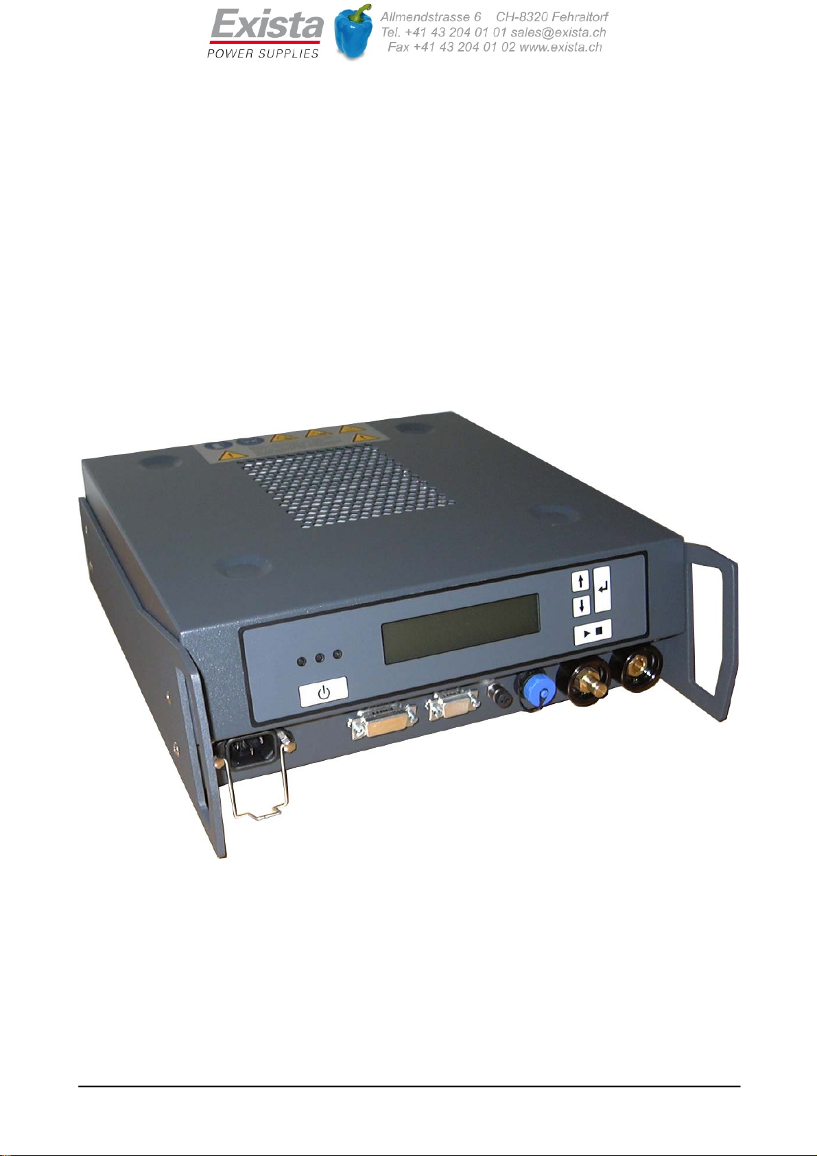
All connections, displays and operating controls are located on the front of the MultiCharger 1500.
Page 8

1.2 Connections
All connections of the MultiCharger 1500 are at the front.
Mains power is connected to the MultiCharger 1500 through a plug for non-heating devices.
3 potential-free relay contacts, which signal various states of the MultiCharger 1500, and also a
hardware contact "Remote On/Off", can be connected through a 15-pole SUB-D socket.
To connect a signal light, a 9-pole SUB-D socket is used.
The signal light (green/yellow/red) signals various states of the MultiCharger 1500. Optionally, a
WLAN box can be connected for configuration, signalling and remote On/Off via PC network.
A sensor cable can be connected to an M8 plugged connector (three-pole socket).
A Mini-USB socket is used for configuration via PC and the software WinCharge. Software
updates can also be carried out through this interface.
The charging cable is connected with a plugged bayonet connection.
Mains power 15-pole 9-pole Sensor Mini-USB L- L+
SUB-D SUB-D socket socket Battery
socket socket connections
1.2.1 9-pole SUB-D socket
A 9-pole SUB-D socket on the front side of the device is used to connect a signal light. The signal
lights (green/yellow/red) signal the following states of the MultiCharger:
State Signal light
MultiCharger off, Standby all LEDs off
MultiCharger on and trickle charging,
Battery fully charged or second current limit
reached
green LED on, yellow LED off, red LED off
MultiCharger on and charging yellow LED on, green LED off, red LED off
MultiCharger not connected yellow LED blinking, green LED off, red LED off
Device defect, poles reversed or flat battery red LED on, green LED off, yellow LED off
Optionally, a WLAN box can be connected for configuration, signalling and remote On/Off via PC
network. Detailed information about this can be found in the description of the WLAN box.
Page 9

1.2.2 15-pole SUB-D socket
A 15-pole SUB-D socket provides 3 potential-free relay contacts, which signal the following states
of the MultiCharger:
State Relay 1 Relay 2 Relay 3
MultiCharger off, Standby 0 0 0
MultiCharger on and trickle charging,
Battery fully charged or second current limit
reached
0 0 1
MultiCharger on and charging 0 1 0
MultiCharger not connected 0 1 1
----- 1 0 0
Device defect 1 0 1
Poles reversed or flat battery 1 1 0
----- 1 1 1
1: relay pulled in 2: Relay released
1.2.3 USB interface
A Mini-USB socket is fitted on the right front side of the MultiCharger 1500, which can be used to
connect a laptop or PC.
The MultiCharger 1500 can be configured through this interface and software updates can be
carried out. For configuration or to alter the device software (Firmware Update) the software
WinCharge is required. Detailed information about this can be found in the description of the PC
Software WinCharge.
The configuration of the interface is shown below:
- data rate 9600 Baud
- 8 Data bits
- 1 Start bit, 1 Stop bit
- no parity
- no protocol
Page 10

1.3 Displays and operating controls
1.3.1 Button 1 (On/Off)
Button 1 is used to switch the MultiCharger 1500 on and off. If the connected mains power voltage
is over 90V, pressing button 1 switches the MultiCharger 1500 on and makes it ready for use.
You will also need to use button 1 to re-enable the system if a fault makes the unit shut down.
1.3.2 Button 2 (Start/Stop)
Button 2 is used to start or stop the charging process or the supply of external power.
1.3.3 Button 3 (Enter)
Button 3 is used as a button to confirm entries and for system navigation.
1.3.4 Button 4 (Up)
Button 4 is a navigation button.
1.3.5 Button 5 (Down)
Button 5 is also a navigation button.
Page 11

1.3.6 LED, green, yellow, red
The LEDs (green/yellow/red) on the display signal the following states of the MultiCharger:
State LED
MultiCharger off, Standby all LEDs off
MultiCharger on and trickle charging,
battery fully charged or second current limit
reached
green LED on, yellow LED off, red LED off
MultiCharger on and charging yellow LED on, green LED off, red LED off
MultiCharger not contacted yellow LED blinking, green LED off, red LED off
Device defect, poles reversed or flat battery red LED on, green LED off, yellow LED off
1.3.7 LC Display
The MultiCharger 1500’s LCD has two lines and can show 16 characters per line.
The current output voltage and current output are displayed on the top line. The bottom line acts as
a status display, showing in plain text the operating state and details of any faults that occur (see
Appendix A).
The LCD is illuminated and can therefore be easily read both in the dark and in direct sunlight.
Page 12

2 Operating modes
2.1 Setting operating mode
You can only set the operating mode if the MultiCharger 1500 is ready for use, i.e. if it has been
switched on via button 1 (On/Off). However, the unit does not have to be charging a battery and no
battery needs to be connected to the charger output.
When you press button 3 (Enter) a prompt to enter a password appears on the LCD display. The
password is made up of four numerical characters and is explained in more detail in section 5.
After correctly entering the password, you get to the MultiCharger 1500’s service menu. You
navigate this menu by using buttons 3, 4 and 5 (see section 5).
The mode is set through the menu item "set operating mode". This can be used to select the
operating modes described below: "Battery operation", "EPS operation 12", "EPS operation 24 V"
and "EPS autostart".
The operating mode for 24 V can only be activated after it has been approved separately under the
menu item "Approve operating mode 24 V".
The MultiCharger 1500 is supplied from the factory set to battery charging mode.
2.2 Battery charging mode (CHRG)
This is the mode used to charge vehicle batteries. The MultiCharger 1500 is ready for use as soon
as you have switched it on by pressing button 1 (On/Off). Ready for use means that the
MultiCharger 1500’s output voltage will remain at zero volts until a battery is attached to the output
connector.
When a battery is connected, the charger first measures the voltage. This determines the battery’s
rated voltage (12V/24V). The output voltage is then set accordingly and the battery starts to be
charged.
The following table gives an overview of valid voltage ranges:
Voltage range MultiCharger
1500
Ready for use
Error
message MultiCharger
1500
At 14.8V
MultiCharger
1500
At 28.8V
0V - 5V x
5V - 7V x
7V - 15V x
15V - 17V x
17V - 30V x
> 30V x
If the voltage of the battery that is connected is outside of one of the permitted ranges, the
MultiCharger 1500 does not switch on, the output voltage remains at 0V and a ‘Faulty battery’ error
message appears on the LCD display.
If the battery voltage is in one of the valid ranges, the MultiCharger 1500 sets the output voltage
accordingly and charges the battery. "Charging active" appears on the LCD display. Charging
continues until the charge current drops below the 2.5A limit. Thereafter the MultiCharger 1500
stays on charge for a preset period (the Default setting is 120 minutes), after which it goes to trickle
charge.
If the current rises back above 2.5A during this secondary charging period or while on trickle
charge, the MultiCharger 1500 switches back to full charging and begins the charge cycle again.
If the charge current fails to drop below 2.5A within a preset period (default setting is 10 hours), the
MultiCharger 1500 switches to trickle charge and the display shows "Charging time max.".
Page 13

The following table gives an overview of the MultiCharger 1500’s default voltage levels:
Charging 12V Trickle
charging 12V Charging 24V Trickle
charging 24V
14.8V 13.4V 28.8V 26.8V
The charging process can be stopped by pressing button 2 (Start/Stop). If the battery remains
connected, the charging process can then be restarted by pressing button 2 (Start/Stop) again. If
the battery is unclamped, the charging process is over and will be restarted automatically if the
battery is connected again.
If the battery is unclamped during the charging process without pressing button 2 (Start/Stop), the
process will likewise be stopped. It will be restarted again automatically if the battery is
reconnected.
Warning:
Unclamping the battery without first properly ending the charging process can briefly create sparks.
The charging process can also be stopped at any time by pressing button 1 (On/Off). When the
MultiCharger 1500 is switched back on the charging process would then begin again from the start.
2.2.1 Output current in battery charging mode
In battery charging mode the MultiCharger 1500 can be briefly (max. 1 minute) subjected to an
output current increased by 25%.
The following table gives an overview of maximum levels of output current for the MultiCharger
1500:
Inom at
12V CHRG Imax at
12V CHRG Inom at
24V CHRG Imax at
24V CHRG
80.0A 100.0A 40.0A 50.0A
If the MultiCharger 1500 rated current is exceeded during use, the unit internally measures how
long this situation lasts. After a maximum of one minute the current limit is reset to the rated value.
To avoid the MultiCharger 1500 overheating the unit allows a period for the charger recover five
times as long as the length of time for which the rated current was exceeded. For example, if the
rated current is exceeded for 30 seconds, the MultiCharger 1500 current limit is held at the level of
the rated current for 2 minutes 30 seconds. After that time, the rated current can again be
exceeded.
Page 14

2.3 External power supply (EPS) mode
This operating mode enables power to be supplied to vehicles that have no battery. Once the
MultiCharger 1500 has been switched on by pressing button 1 (On/Off), it is ready for use. That
means that the MultiCharger 1500’s output voltage will stay at zero volts until button 2 (Start/Stop)
is pressed.
The MultiCharger 1500 then goes on to charge at the relevant voltage.
The following table gives an overview of the factory-set voltage levels for the EPS mode:
EPS 12V mode EPS 24V mode
14.0V 28.0V
The output voltage on the MultiCharger 1500 remains switched on until button 2 (Start/Stop) is
pressed again. When you press this button, the MultiCharger 1500 switches output voltage to 0V
until button 2 (Start/Stop) is pressed once again. Then output voltage is switched back on again.
Output voltage can also be switched off by pressing button 1 (On/Off).
Connecting a battery (with a voltage of >1V) to the MultiCharger 1500 before the output voltage is
switched on is not allowed. If this is done, a ‘Return voltage’ error message will appear.
The output voltage on the MultiCharger 1500 can then not be switched on until the battery is once
again removed.
Warning:
Connecting a battery to the MultiCharger 1500 while it is in EPS mode is not allowed.
2.4 EPS autostart mode
This mode works in a similar way to EPS mode. The difference between the two operating modes
is that in EPS autostart mode a battery has to be connected to the MultiCharger 1500.
The MultiCharger 1500 then sets the output voltage automatically to match the battery that is
attached.
2.5 Charging AGM batteries
It is possible that the batteries used in some vehicles may be so-called AGM (Absorbent Glass
Mat) batteries, i.e. batteries containing an absorbent glass-fibre mat.
With these batteries, you should make particularly sure that in no event does the charging voltage
exceed 14.8V (or 29.6V in the case of 24V batteries).
When AGM batteries are used, adjustments to the MultiCharger 1500’s output voltage (see section
5.4) must therefore be made with particular care.
Warning: Any AGM battery will be permanently damaged if the charging voltage exceeds
14.8V (or 29.6V in the case of 24V batteries).
The MultiCharger 1500 is supplied with the output voltage set below the allowable limit for AGM
batteries.
Page 15

2.6 Charging Gel batteries
Gel batteries are used in some vehicles.
With these batteries, you should make particularly sure that the charging voltage is between 14.1V
and 14.8V (or 28.2 - 28.8V in the case of 24V batteries).
The trickle charge voltage should not exceed 13.8V (or 27.6V in the case of 24V batteries).
When Gel batteries are used, adjustments to the MultiCharger 1500 output voltage (see section
5.4) must therefore be made with particular care.
The charging current should be between 15 - 40A for every 100Ah of battery capacity. Refer to the
technical specifications of the relevant Gel battery for the maximum permitted current.
Warning:
If a Gel battery’s charging voltage or trickle charge voltage exceeds the levels shown
above, battery life will be shortened. If these levels are regularly exceeded, the battery will
be permanently damaged.
2.7 Charging motorcycle batteries
Motorcycle batteries generally have a significantly smaller capacity than car batteries. This can
lead to the MultiCharger 1500 maximum charging current (100A for 12V batteries) being too high
for some types of battery.
Should this be the case, the MultiCharger 1500 output current limit should therefore be set lower
(see section 5.6).
For the maximum permitted charging current, refer to the technical specifications of the relevant
motorcycle battery.
Page 16

3 Internal monitoring
The MultiCharger 1500 has several internal monitoring functions that ensure that the charger
works reliably. These are individually described in the following sub-sections.
3.1 Mains power monitoring
If the mains voltage drops below 85V, the MultiCharger 1500 signals a fault and switches off. The
message ‘Mains error’ appears on the LCD display.
If the mains voltage rises above 90V, the MultiCharger 1500 can be made ready for use by
pressing button 1 (On/Off).
3.2 Monitoring intermediate circuit voltage
Intermediate circuit voltage is monitored both against dropping too low and rising too high. If either
limit (350V and 430V respectively) is passed, the MultiCharger 1500 signals a fault and switches
itself off to the unlocked position. The message ‘PFC error’ appears on the LCD display and the
red LED comes on. If either of the limits is exceeded again after restarting the MultiCharger 1500
switches itself off to the locked position.
3.3 Output overvoltage protection
For safety reasons output voltage is monitored for excessive levels in two totally independent
ways.
The controller-independent hardware monitoring threshold for overvoltage output is fixed at 16V or
32V respectively. This monitors internal output voltage. If internal voltage goes over this threshold,
the MultiCharger 1500 signals a fault and switches itself off to the locked position. The message
‘OVP error’ appears in the LCD display and the red LED comes on.
The digital monitoring threshold for overvoltage output is adjustable, while the default setting for
this is also 16V or 32V respectively. If output voltage goes over this threshold, the MultiCharger
1500 signals a fault and switches itself off to the locked position. The message ‘Overvoltage’
appears in the LCD display and the red LED comes on.
3.4 Output undervoltage protection
The monitoring threshold for output undervoltage is 7V or 14V respectively.
If output voltage drops below this threshold, the MultiCharger 1500 signals a fault and switches
itself off to the locked position. The message ‘Voltage too low’ appears on the LCD display and the
red LED comes on.
3.5 Excessive output current
If, due to an internal fault in the appliance, output current exceeds the prevailing current limit level
by more than 25%, the MultiCharger 1500 signals a fault and switches itself off to the locked
position. The message ‘Overcurrent’ appears in the LCD display and the red LED comes on.
Page 17

3.6 Temperature monitoring
This monitoring function measures the temperature inside the MultiCharger 1500. If this rises
above the maximum limit of 90°C, the MultiCharger 1500 signals a fault and is switched off, but not
locked. The message ‘Temperature err.’ appears on the LCD display and the red LED comes on.
The MultiCharger 1500 remains ready for use.
If the temperature drops back below the maximum level, the error message is automatically
cancelled.
3.7 Relay monitoring
This function monitors the internal relay switches in the MultiCharger 1500’s main circuit. If there is
a problem with any of these, the MultiCharger 1500 signals a fault and switches itself off to the
locked position. The message ‘Internal error’ appears on the LCD display and the red LED comes
on.
Page 18

4 External monitoring
The MultiCharger 1500 also has a number of external monitoring functions that keep a constant
check on connected power consumers. These are individually described in the following sub-
sections.
4.1 Short circuit
The MultiCharger 1500 can tell that it has an output short circuit if this occurs in the current limiter
and output voltage drops below the set lower limit (default setting 7V or 14V respectively). In this
case, the MultiCharger 1500 signals a fault and switches itself off to the locked position. The
message ‘Short circuit’ appears on the LCD display and the red LED comes on.
4.2 Reverse polarity
If a battery is connected the wrong way round, the MultiCharger 1500 signals a fault but remains
ready for use. This does not do the MultiCharger 1500 any harm. No charging or trickle charging
process will be started. ‘Reverse polarity’ appears on the LCD display and the red LED comes on.
4.3 Faulty battery
If the battery connected to the charger has an output voltage outside of the permitted limits (see
section 2.2), the MultiCharger 1500 signals a fault and the charging process des not start. The
message ‘Faulty battery’ appears on the LCD display and the red LED comes on.
4.4 Clamp contact
This monitoring function is active in all operational modes; Battery charging mode (see section 2.2)
EPS operation (see section 2.3) and in EPS autostart mode (see section 2.4).
If the MultiCharger 1500’s output current drops below 10mA during the charging or trickle charging
process, the MultiCharger 1500 recognises this as meaning that the clamps have been removed
from the battery posts. The charger then briefly signals a fault, the message ‘Clamp contact’
appears on the LCD display and the red LED comes on. However, the MultiCharger 1500 remains
ready for use.
4.5 Return voltage
This monitoring function is only active in EPS mode (see section 2.3).
You are not permitted to connect a battery to the MultiCharger 1500 in this operating mode. If you
do nevertheless connect a battery ahead of trying to start to charge it, the MultiCharger 1500
signals a fault. The message ‘Return voltage’ appears on the LCD display and the red LED comes
on. The MultiCharger 1500 remains ready for use.
Page 19

4.6 Reverse polarity return voltage
This monitoring function is only active in EPS mode (see section 2.3).
You are not permitted to connect a battery to the MultiCharger 1500 in this operating mode. If you
do nevertheless connect a battery before trying to start charging, and connect it the wrong way
round, the MultiCharger 1500 signals a fault. This will not harm the MultiCharger 1500, but the
message ‘EPS reverse pole’ appears on the LCD display and the red LED comes on. The
MultiCharger 1500 remains ready for use.
Page 20
Other manuals for MultiCharger 1500
1
Table of contents
Other Eltek Batteries Charger manuals


